EP2573301A2 - Fermeture arrière pour un véhicule automobile - Google Patents
Fermeture arrière pour un véhicule automobile Download PDFInfo
- Publication number
- EP2573301A2 EP2573301A2 EP12180545A EP12180545A EP2573301A2 EP 2573301 A2 EP2573301 A2 EP 2573301A2 EP 12180545 A EP12180545 A EP 12180545A EP 12180545 A EP12180545 A EP 12180545A EP 2573301 A2 EP2573301 A2 EP 2573301A2
- Authority
- EP
- European Patent Office
- Prior art keywords
- pawl
- movement
- rotary latch
- rear lock
- rotary
- Prior art date
- Legal status (The legal status is an assumption and is not a legal conclusion. Google has not performed a legal analysis and makes no representation as to the accuracy of the status listed.)
- Granted
Links
Images


Classifications
-
- E—FIXED CONSTRUCTIONS
- E05—LOCKS; KEYS; WINDOW OR DOOR FITTINGS; SAFES
- E05B—LOCKS; ACCESSORIES THEREFOR; HANDCUFFS
- E05B77/00—Vehicle locks characterised by special functions or purposes
- E05B77/42—Means for damping the movement of lock parts, e.g. slowing down the return movement of a handle
-
- E—FIXED CONSTRUCTIONS
- E05—LOCKS; KEYS; WINDOW OR DOOR FITTINGS; SAFES
- E05B—LOCKS; ACCESSORIES THEREFOR; HANDCUFFS
- E05B81/00—Power-actuated vehicle locks
- E05B81/12—Power-actuated vehicle locks characterised by the function or purpose of the powered actuators
- E05B81/14—Power-actuated vehicle locks characterised by the function or purpose of the powered actuators operating on bolt detents, e.g. for unlatching the bolt
-
- E—FIXED CONSTRUCTIONS
- E05—LOCKS; KEYS; WINDOW OR DOOR FITTINGS; SAFES
- E05B—LOCKS; ACCESSORIES THEREFOR; HANDCUFFS
- E05B81/00—Power-actuated vehicle locks
- E05B81/12—Power-actuated vehicle locks characterised by the function or purpose of the powered actuators
- E05B81/20—Power-actuated vehicle locks characterised by the function or purpose of the powered actuators for assisting final closing or for initiating opening
Definitions
- a rear lock of the aforementioned type which can be referred to quite generally as a motor vehicle door lock, is for example from the DE 10 2007 024 672 A1 known and used for example in a tailgate of a motor vehicle.
- a rear lock or such a motor vehicle door lock comprises a lock element, which is connected to a boot lid and is usually equipped with a rotary latch, and a lock counterpart connected to a body of the motor vehicle, which may be in the form of a striker or striker.
- a user actuates (eg by means of an electronic key) a control device, by means of which the tailgate can be opened by means of a drive element, which is preferably operated by an electric motor.
- the invention has for its object to provide a solution that provides a rear lock or a motor vehicle door lock in a structurally simple manner and cost, in which the opening noise is reduced to a minimum, or at least in which the opening process no clearly audible and the comfort negatively impairing Noise generated.
- delay means are provided which are coupled to the rotary latch to delay a speed of movement of the rotary latch to release the closing element.
- the movement of the rotary latch in the rear lock according to the invention can be a rotation or rotational movement. It may also be several delay means or even a single delay means. In the further course of the description, therefore, the input and the plurality of delay means are simultaneously addressed.
- a rear lock but also quite generally a motor vehicle door lock, available which enhances the comfort and quality of the closure and its operation.
- the motor vehicle door lock according to the invention in particular the rear lock, is characterized by a functional design and has a simple and inexpensive construction. Due to the delayed movement of the rotary latch and the trigger mechanism of the motor vehicle door lock and the rear lock according to the present invention, the pawl and the rotary latch during a movement operation of the pawl in the direction of the release position are still in engagement. Although this movement does not allow the opening of the tailgate.
- the bias of the tailgate degrades because the defined and delayed movement of the pawl causes a relative movement between the motor vehicle door lock and the closing element and thus relieving the tailgate, wherein the rotary latch to a predetermined rotational movement is turned in the open position.
- the invention provides that the bias between the tailgate or motor vehicle door lock and closing element is reduced before the pawl and the rotary latch are disengaged.
- the invention also provides a motor vehicle door lock with a locking element in the closed position and in the direction of an open position releasing the open position biased latch, a pawl which engages in an engaged position with the rotary latch in such a manner that the rotary latch on a movement in the direction of the open position is prevented, and a drive element, with which a coupling portion of the pawl is coupled for movement and which the pawl between the engaged position and a Release position moves, in which the pawl with the catch is disengaged, so that the catch can move in the direction of the open position, the task here is inventively achieved in that the drive element, the pawl during movement from the engaged position in the direction of the release position moved so that during this movement with the pawl still engaged rotary catch moves in the direction of the open position.
- the controlled movement of the pawl can be realized in an embodiment of the rear lock according to the invention and also a general motor vehicle door closure that a pivotable about a pivot rotary joint is provided, which is rotatable about a rotation axis pawl mounted on the pivot radially offset from the pivot point.
- a pivotable about a pivot rotary joint is provided, which is rotatable about a rotation axis pawl mounted on the pivot radially offset from the pivot point.
- the invention provides in an embodiment of a push rod, of which a first end is pivotally and radially offset from a rotational axis of a rotary lever or radial approach is coupled thereto and coupled by a second end to the rotary joint in the region of the axis of rotation of the pawl such is that moves the axis of rotation of the pawl along a circular segment-shaped trajectory about the pivot point of the pivot joint during movement of the push rod.
- a first toggle lever is defined by the second end of the push rod and the fixedly mounted pivot, wherein the pawl is coupled via the rotation axis with the pivot and with the push rod.
- a second toggle lever is defined by the first end of the push rod and its eccentric or radially offset with respect to the axis of rotation coupling with the rotary lever, so that a total of a double toggle is present.
- the invention provides that the rotary joint is coupled with a variable-length lever, which is designed to brake the movement of the pawl from the engaged position to an intermediate position and braking from the intermediate position into the release position.
- a variable-length lever which is designed to brake the movement of the pawl from the engaged position to an intermediate position and braking from the intermediate position into the release position.
- This configuration causes the movement of the pawl from the engaged position to the release position and back to the engaged position by a motor-driven Drive element is controlled guided.
- the drive element is used in a first movement section from the engaged position to an intermediate position as a drive for the pawl, whereas the drive element acts as a brake during the movement of the pawl from the intermediate position to the release position.
- the change in the operation of the drive element results from the fact that the intermediate position defines a load change for the drive element.
- the invention provides that the intermediate position is a dead center of the pawl, in which at least the force acting on the pawl force of the catch and the axis of rotation of the pawl are arranged lying in a line.
- the dead center position or intermediate position describes a position of the pawl, which can only be changed by a force transverse to the line, which is formed by the axis of rotation and the force acting on the pawl force of the rotary latch.
- the delay means simultaneously effect an actuation of the pawl.
- the delay means serve not only the delay of the movement of the rotary latch, but also an actuation and possibly movement of the pawl.
- the rotary joint and / or the push rod and / or the drive element may be the delay means, which allows a simple and inexpensive construction of the rear lock and the motor vehicle door lock.
- the invention provides a damping element, in particular a mechanical, hydraulic or pneumatic damping element, serves as a retarding means.
- the damping element may be a linear damping element, wherein the damping element does not serve as an end stop for cushioning the end movement of the rotary latch, but rather dampens, brakes and thereby delays the initial movement of the rotary latch.
- This movement refers to a latching portion of the pawl, which engages in the engaged position with the rotary latch.
- the drive element for opening the motor vehicle door lock is rotated such that the pawl or at least a portion of the pawl, ie the latching portion, initially during movement from the engaged position in the direction of the release position is moved substantially tangentially with respect to the rotary latch and then to disengage the pawl and the catch, is moved substantially radially away from the catch.
- the movement of the pawl executed during the opening process of the motor vehicle door lock is thus divided into two or consists of a sequence of movements in which the pawl is moved in at least two different spatial directions. To initially take the pressure from the tailgate in the closed position or to relieve the preloaded tailgate, there is a substantially tangential movement of the pawl with respect to the rotary latch.
- the pawl In this movement, the pawl is still engaged with the catch, but depending on the tangential distance to which the Pawl is moved, the rotary latch allows a rotation in the open position, whereby the pressure of the tailgate degrades. Only after the pressure reduction or the reduction of the bias is then carried out with the help of the radial sideways movement of the pawl disengage the catch, which then releases the closing element for opening the tailgate.
- the resulting from at least two movements in different directions in space opening movement of the pawl thus allows the degradation of acting on the tailgate in the closed position bias by the pawl causes a controlled movement of the tailgate in the opening direction for a certain stroke.
- the invention also provides that the axis of rotation of the pawl during the movement of the pawl in Direction of the release position relative to the axis of rotation of the rotary latch, preferably translationally moves.
- the pawl is indeed still engaged with the rotary latch, however, can rotate due to the translational and tangential to the rotary latch movement of the pawl, the rotary latch in the direction of its open position.
- the bias voltage with which the tailgate is biased in the closed position is degraded gradually and not abruptly, it is in the rear lock and motor vehicle door lock further advantageous if the movement from the engaged position in the direction of the release position of the pivot on the pivot or rotatable attached axis of rotation of the pawl is a circular section-shaped movement. It is conceivable, for example, quarter-circle or semi-circular movements.
- a structurally particularly simple way for defined guidance of the pawl in the release position continues to be that in the engaged position with the catch in engagement locking portion of the pawl is guided by means of a guide member and / or mounted on the pawl control pin movement.
- the pawl is moved radially away from the rotary latch during the opening process, it being particularly advantageous if only the engaging with the catch portion of the pawl, ie the latching portion, and not the entire pawl moves away from the rotary latch becomes.
- a particularly favorable transmission of the driving force of the drive element to the pawl is possible by a transmission lever which is in operative connection with the pawl. According to the invention, the advantages given by a lever in terms of power transmission are used here.
- the transmission lever is provided with a slot in which a movement-coupled with the pawl pin is guided.
- the mechanical coupling of pin and transmission lever is reminiscent of a kind of slotted guide, but in contrast, the transmission lever, depending on the position, which is caused by the rotational movement of the transmission lever rotating drive element, a forced movement of the pin in the slot.
- the leverage changes due to the pin slidably held in the slot, since in particular the lever length of the transmission lever varies depending on the position of the pin. In this way, the invention provides a kind of variable-length lever.
- the invention provides in an embodiment that the pivotally mounted about the pivot pivot lever forms an operative connection between the transmission lever and the pawl, wherein the pin and the coupling portion each offset radially to the pivot point the articulated lever is arranged on the toggle lever and are mounted so that a movement of the pin directly rotates the toggle lever and indirectly rotates the axis of rotation.
- the pawl is biased in the direction of the engagement position.
- the pawl is permanently urged in the direction of the engagement position, which can be achieved for example by means of at least one spring element, which may be formed as a tension or compression spring. It is sufficient if only the portion of the pawl is biased, which can be brought into engagement with the rotary latch or is in engagement with the rotary latch.
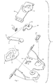
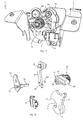
- the closing element 2 may be formed, for example, as a locking pin or striker and is attached to a vehicle frame.
- the in FIG. 1 shown in an exploded view of the motor vehicle door closure 1 according to the first embodiment comprises interconnectable housing elements 3 and 4, a rotary latch 5 which is rotatably mounted about an axis of rotation 6 on the housing element 2 and a rotary latch jaw 7, in which the closing element 2 engages.
- the rotary latch 5 is characterized by a in FIG.
- the pawl 9 is connected via a rotary joint 12 with a motion element not shown in detail for the first embodiment drive element.
- the rotary joint 12 is rotatably mounted on the housing element 4 about a rotation axis (pivot point 13).
- a bolt-shaped connecting element is mounted as a rotation axis 14 for the pawl 9, which is arranged radially offset from the pivot point 13 on the pivot joint 12 and attached thereto.
- the connecting element in the form of the axis of rotation 14 connects the coupled to the drive element pivot 12 with a arranged in the region of the rotation axis 14 coupling portion 15 of the pawl 9, so that the pivot joint 12, the pawl 8 between the engaged position and a release position in which the pawl 9 with the catch 5 is disengaged moves.
- the pawl 9 is thus pivotally connected by means of the connecting element or the axis of rotation 14 the rotary joint 12 radially offset from the pivot point 13 stored.
- the rotary latch 5 can move or rotate in the direction of the open position.
- the pawl 9 is biased in the direction of the engagement position, which, for example, by means of an example only in FIG FIG. 3 It is sufficient if the area of the latching portion 10 of the pawl 9 is urged by the spring force in the engaged position and thus in the direction of the rotary latch 5 and the latching arm 11 of the rotary latch 5.
- the invention provides that the coupled to the drive element pivot 12 moves the pawl 9 during movement from the engaged position in the direction of the release position in that the rotary catch 5, which is still in engagement with the pawl 9 during this movement, moves in the direction of the open position.
- the coupled with the catch 5 pawl 9 acts here as a delay means to delay the speed of opening the movement, in particular the rotational movement of the catch 5 to release the closing element 2 and simultaneously avoiding the opening noise and slow down.
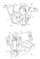
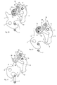
- FIGS. 4 to 7 is a movement curve 17 of the rotation axis 14 and the coupling portion 15 which is connected via the rotation axis 14 and the rotary joint 12 with the drive element, shown in dashed lines.
- the movement curve 17 essentially corresponds to the control recesses 18 and 19, which are formed in the housing elements 3 and 4. From the movement curve 17, it can be seen that the movement of the coupling portion 15 of the pawl 9, which is pivotally mounted on the rotation axis 14, from the position of engagement in the direction of the release position is a circular-segment-shaped movement, which is shown in FIGS FIGS. 4 to 7 counterclockwise in the direction of arrow A.
- a rotational movement or rotational movement of the rotary joint 12 about the pivot point 13 causes the coupling section 15 or the rotational axis 14 of the pawl 8 to be moved along a circular section.
- the control recesses 18 and 19 formed in the housing elements 3 and 4 can additionally guide the movement of the axis of rotation 14.
- the control recesses 18 and 19 are dispensable, so that they can be omitted in the motor vehicle door lock or rear lock 1 according to the invention.
- the pawl 8 is moved by the rotary joint 12 during movement from the engaged position in the direction of the release position such that in this movement with the pawl 9 still engaged rotary latch 5 is moved in the direction of the open position ,
- the rotary joint 12, which is coupled to the drive element, is rotated to open the motor vehicle door lock or the rear lock 1 such that the pawl 9 or at least a portion of the pawl 9 (ie the latching portion 10) initially during movement from the engaged position in the direction the release position is moved substantially tangentially with respect to the rotary latch 5 and then, in order to disengage the pawl 9 and the catch 5, is moved substantially radially away from the rotary latch 5.
- the latching portion 10, which is in the engaged position of the pawl 9 with the rotary latch 5 is engaged, is guided by means of a guide member 20 movement.
- the guide member 20 is on the housing member 3 of the motor vehicle door lock or rear lock langordnet and pivotally mounted about an axis 21 thereto.
- the guide element 20 has a guide recess 22 with two opposing abutment surfaces, which leads or controls a movement of the engageable with the catch 5 locking portion 10 of the pawl 9 toward the rotary latch 5 or away from the rotary latch.
- the movement of a control pin 23 can be performed, which is formed in the region of the latching portion 10 of the pawl 9 (see FIGS. 4 and 8 ).
- the movement of the guide element 20 itself can be achieved by a movement limiting recess 24 formed in the housing element 3 (see FIG FIG. 1 ) be limited.
- the latching portion 10 of the pawl 9 may, as mentioned above, be biased in the direction of the engagement position by means of the spring element 16, so that the formed in the region of the locking portion 10 control pin 23 during the in the FIGS. 4 to 7 shown movement is urged radially in the direction of the rotary latch 5 at the extreme end of the formed in the guide member 20 guide recess 22.
- a radial movement away from the rotary latch 5 could be effected by itself.
- an outer portion of the rotary latch 5 could have a radial projection 25, as in FIG FIG. 4 indicated by dashed lines or shown.
- the radial projection 25 would arrive at sufficient rotation in abutment with the pawl 9 and the Pawl 9 push away or deflect such that the locking portion 10 and the locking arm 11 are disengaged.
- FIG. 8 a position of the rear lock or the motor vehicle door lock 1 is shown during the closing operation, in which the coupling portion 15 of the pawl 9 is again in the engaged position, whereas the locking portion 10 of the pawl 9 is disposed radially away from the rotary latch 5, wherein the control pin 23rd a central position in the guide recess 22 of the guide member 20 occupies. Due to the fact that the control pin 23 of the locking portion 10 can be urged radially against the force of the spring element 16 in the guide recess 22 of the guide member 20 away from the rotary latch 5, it is possible that the rotary latch 5 rotates in the direction of arrow B during the closing operation and in this movement, the latching arm 11 slides past the latching section 10.
- the bias of the pawl 9 ensures that when the latching arm 11 has passed the latching portion 10, both interlock or that the latching portion 10 then pushes over the latching arm 11 and ensures engagement of pawl 9 and 5 catch, so that in FIG. 4 shown closed position is taken again.
- the process of closing but should not be considered here in detail, because the invention is primarily directed to the processes when opening the motor vehicle door lock or the rear lock. 1
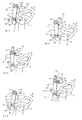
- FIGS. 9 to 13 the motor vehicle door lock or the rear lock 1 according to the second embodiment is shown.
- the motor vehicle door lock or the rear lock 1 according to the second embodiment - as well as the first embodiment - the housing element 3, which for reasons of clarity, only in FIG. 9 is shown, around and on the axis of rotation 6 rotatably mounted rotary latch 5 with the rotary latch jaw 7, in which the closing element 2 is arranged in the engaged position, and with the locking arm 11, which with the locking portion 10 of the pawl 9 in the engaged position is engaged, and with a drive element 26 (see, eg FIG.
- the pawl 9 is connected to the rotary joint 13 coupled for movement.
- this coupling between the first and second embodiments, which will be discussed later in the description of the second embodiment.
- the coupling section 15 of the pawl 9 is mounted or mounted pivotably on the rotary joint 12 via the axis of rotation 14.
- the rotation axis 14 is not stationary in contrast to the rotation axis 6, but moves during the movement of the pawl 9 in the direction of the release position relative to the axis of rotation 6 of the rotary latch 5 translationally along in the FIGS. 12 and 13
- the coupling section 15 of the pawl 9 undergoes a circular segment-shaped movement which is not a rotational movement but a substantially translational movement with respect to the rotary latch 5.
- the first end 29 of the push rod 28 is mounted radially offset from a rotational axis 30 of the drive element 26 on a radial shoulder 31 of the drive element 26 on this rotatable or pivotable.
- the push rod 28 is slightly bent, wherein a second end 32 of the push rod 28 receives the movement coupled to the coupling portion 15 of the pawl 9 pivot 12 and the rotational axis 14 of the pawl 9.
- the rotary joint 12 is rotatably mounted on the attached to the housing element 3 pivot point 13.
- the movement of the second end 32 of the push rod 28 is guided by the rotary joint 12 along the movement curve 17, so that thereby also the rotation axis 14 and the coupling portion 15 of the pawl 9, which are coupled to the second end 32 of the push rod 28, along move the movement curve 17.
- the coupling portion 15 of the pawl 9 undergoes a substantially circular segment-shaped movement.
- the movement of the latching section 10 out of the engagement position in the direction of the release position is in a first movement section a movement of the latching section 10 substantially tangential with respect to the rotary latch 5, which is characterized by the vertical course of the movement path 33.
- the pawl 9 is still engaged with the rotary latch 5 in engagement.
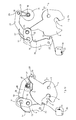
- FIGS. 14 to 22 is a motor vehicle door lock or a rear lock 1 shown according to a third embodiment.
- the rear lock 1 according to the third embodiment includes only in the FIGS. 14 to 22 schematically illustrated closing element 2, which may be attached to a vehicle frame, when the rear lock 1 is attached to the tailgate. It is also conceivable, of course, that the closing element 2 can be attached to the tailgate and the rear lock 1 to the vehicle frame.
- the motor vehicle door lock 1 further comprises the only in FIG. 14 shown housing element 3, in which further components of the motor vehicle door lock 1 added, under and are attached. For clarity, the housing element 3 in the FIGS. 15 to 22 not shown further.
- the motor vehicle door lock 1 additionally comprises the rotary latch 5, which is rotatably mounted about the axis of rotation 6 on the housing element 3 and which has the rotary latch jaw 7, in which the closing element 2 engages in the closed position.
- the catch 5 is biased by a spring element not shown in more detail or spring (force) acted upon or spring preloaded that it strives to, for example, in FIG. 17 shown closed position or closed position to rotate clockwise about the axis of rotation 6, so that the rotary latch 5 in the open position, the closing element 2 with respect to FIG. 22 releases downwards.
- the rotary latch 5 engages in the closed position, the closing element 2, wherein it is biased in the direction of the closing element 2 releasing open position.
- the pawl 9, which is at least pivoted to open the rear lock (motor vehicle door lock) 1 and is brought out of engagement with the rotary latch 5, with the interposition of the rotary joint (articulated lever) 12 is connected to the drive member 26 and coupled for movement, wherein the drive member 26 can be driven by a motor, not shown, for example with worm gear with helical teeth.
- drive member 26 is shown partially cut to also represent components that are located lying behind the drive element 26.
- the rotary joint or the articulated lever 12 is plate-shaped or disc-shaped and rotatably mounted on the housing element 3 about the pivot point 13.
- the drive element 26 moves the pawl 9 such that during this movement with the pawl 9 still engaged rotary latch 5 is moved or moved in the direction of the open position.
- the movement of the drive member 26 is a rotational movement, during the movement of the pawl 9 from the engaged position in the direction of the release position with respect to the rotary latch 5 substantially tangential movement of the pawl 9 and then to the pawl 9 and the catch 5 except To bring about a substantially radially away from the rotary latch 5 pioneering movement of the pawl 9 causes.
- the pin 39 and the coupling portion 15 and the rotational axis 14 of the pawl 9 are each radially offset from the pivot point 13 of the pivot joint (articulated lever) 12 at the pivot (articulated lever) 12 is arranged and mounted.
- a rotation of the drive member 26 in a clockwise direction (with respect to the FIGS. 17 to 21 ) in the direction of the arrow D causes a rotational movement of the rotary joint (articulated lever) 12 also in a clockwise direction (in the direction of arrow C), whereby the eccentrically or radially offset to the pivot point 13 and rotatably mounted on the rotary joint (articulated lever) 12 rotational axis 14th the pawl 9 in the region of the coupling portion 15 rotates and moves in a circle-shaped manner about the pivot point 13 of the swivel joint (articulated lever) 12, whereas the latching portion 10 of the pawl 9 of the above-described tangential and then radial movement curve 33 (see, for example FIG. 17 ) follows during the opening process.
- a movement of the pin 39 rotates directly the pivot (articulated lever) 12 and indirectly the coupling portion 15 of the pawl.
- the drive element 26 initially absorbs kinetic energy before the load acts on the transmission lever 38 for moving the pawl 9.
- the drive element 26 moves from a starting start position AS in a Anfahrendposition AE, the drive element 26 moves only after reaching the Anfahrendposition AE the pawl 9 from the engaged position in the direction of the release position.
- the starting start position AS and the starting end position AE are in FIG. 18 indicated, wherein the dashed line represents the position of the transmission lever 38 in the starting start position AS.
- the drive element 26 Upon movement of the drive element 26 between the starting start position AS and the Anfahrendposition AE standing in operative connection with the pawl 9 pin 39 is not moved. Rather, the drive element 26 rotates from the starting start position AS, to receive sufficient momentum or sufficient kinetic energy until reaching the Anfahrendposition AE so that the pawl 9 can be moved in the direction of the release position , Thus, the pin 39 is not moved during this rotational movement of the drive member 26, whereby the drive member 26 would be charged, the slot 40 has a neutral radius, which is synonymous with a freewheeling portion 41 (see FIG. 16 ).
- the freewheeling section 41 extends in a circular section in an angular range ⁇ between 18 ° and 32 ° about the axis of rotation (Fulcrum) 30 of the drive element 26.
- the freewheel defining angle range ⁇ is approximately 20 °, wherein the total opening rotational movement of the drive element 26 about the rotation axis (pivot point) 30 is less than 180 °.
- the drive element 26 the movement of the pawl 9 from the engaged position in the intermediate position driving and braking from the intermediate position into the release position is formed, the drive element 26 acts behind the dead center position as a brake, the movement of the pawl 9 completely by the drive element 26th is guided from the engaged position to the release position and the drive member 26 holds the pawl 9 quasi after exceeding the intermediate position or the dead center and prevents the movement of the pawl 9 is accelerated.
- the latching section 10 performs a substantially tangential movement with respect to the rotary latch 5, wherein the pawl 9 continues to engage with the rotary latch 5, but after the dead center has been exceeded turns in the direction of the open position.
- the latching portion 10 of the pawl 9 is moved radially away from the rotary latch 5, to disengage the pawl 9 and the rotary latch 5.
- the motor vehicle door lock 1 comprises a guide element 44, which in FIG. 15 is shown in a single part representation. By the guide member 44, it is the pawl 9 when returning from the open position into the closed position only then possible to engage in the catch when the axis of rotation 14 of the pawl substantially in FIG. 17 shown position along the circular segment-shaped movement curve 17 has taken.
- the swivel joint 12 or the push rod 28 or the drive element 26 may be the delay means.
- any combination of the three components (pivot 12, push rod 28, drive member 26) or all three components together can represent the delay means to the rotational speed of the rotary latch 5 during the opening process at least initially, ie for example in a first third of the movement from the closed position in Direction of the open position, to delay.
- the delay is controlled, ie the rotational speed is controlled by the delay means, including in the three preceding Embodiments the pawl 9 is used, via which the rotary latch 5 is coupled to the / the delay means.
- the rotary joint 12 which is rotatable about the pivot point 13, wherein the pivotable about the rotation axis 14 pawl 9 is mounted on the pivot 12 radially offset from the pivot point 13.
- the push rod 28 may be the retarder alone or together with the pivot 12.
- a first end 29 of the push rod 28 is pivotally and radially offset from the rotational axis 30 of the rotary lever or radial shoulder 31 coupled thereto, wherein the second end 32 of the push rod 28 is coupled to the pivot 12 in the region of the axis of rotation 14 of the pawl 9 so that during movement of the push rod 28, the rotational axis 14 of the pawl 9 along a circular-segment-shaped movement path 17 moves about the pivot point 13 of the rotary joint 12.
- the drive member 26 may be provided as a delay means, the drive member 26 causes the movement of the pivot joint 12 about the pivot point 13 in the movement of the pawl 9 from the engaged position to the release position around and controlled and delayed.
- a damping element which may in particular be a mechanical, hydraulic or pneumatic damping element, serve as an alternative delay means.
- Such serving as a delay means damping element would then act directly on the rotary latch 5 and the rotational movement of the rotary latch 5 from the closed position to possibly delay the open position linear, where it may be sufficient in terms of avoiding the disturbing opening noise when the delay means the first third of Rotary movement of the rotary latch 5 delays the degradation of the bias of the tailgate due to a compressed seal.
- the delay means is designed as acting on the rotary latch 5 damping element, the delayed movement of the rotary latch 5 is decoupled to release the closing element 2 of the pawl 9. Only the pawl 9 must be disengaged from the catch 5, which can be done at the beginning of the opening process, in which case, after the pawl 9 is no longer engaged with the rotary latch 5, that damping element caused by a spring element rotational movement of the rotary latch. 5 delayed accordingly.
- the invention includes everything that is contained in the description and / or illustrated in the drawing, including what is obvious to the person skilled in the art, which deviates from the specific exemplary embodiments.
Landscapes
- Lock And Its Accessories (AREA)
Applications Claiming Priority (5)
| Application Number | Priority Date | Filing Date | Title |
|---|---|---|---|
| DE102011053901 | 2011-09-23 | ||
| DE201210102723 DE102012102723A1 (de) | 2011-09-23 | 2012-03-29 | Kraftfahrzeugtürverschluss |
| DE201210107145 DE102012107145A1 (de) | 2012-08-03 | 2012-08-03 | Kraftfahrzeugtürverschluss |
| DE102012107144.6A DE102012107144B4 (de) | 2012-08-03 | 2012-08-03 | Kraftfahrzeugtürverschluss |
| DE201210107143 DE102012107143A1 (de) | 2012-08-03 | 2012-08-03 | Kraftfahrzeugtürverschluss |
Publications (3)
| Publication Number | Publication Date |
|---|---|
| EP2573301A2 true EP2573301A2 (fr) | 2013-03-27 |
| EP2573301A3 EP2573301A3 (fr) | 2014-02-19 |
| EP2573301B1 EP2573301B1 (fr) | 2017-05-03 |
Family
ID=46963389
Family Applications (1)
| Application Number | Title | Priority Date | Filing Date |
|---|---|---|---|
| EP12180545.1A Active EP2573301B1 (fr) | 2011-09-23 | 2012-08-15 | Fermeture arrière pour un véhicule automobile |
Country Status (1)
| Country | Link |
|---|---|
| EP (1) | EP2573301B1 (fr) |
Cited By (9)
| Publication number | Priority date | Publication date | Assignee | Title |
|---|---|---|---|---|
| US20130076045A1 (en) * | 2011-09-23 | 2013-03-28 | Huf Hulsbeck & Furst Gmbh & Co. Kg | Motor vehicle door latch |
| CN103541610A (zh) * | 2013-11-01 | 2014-01-29 | 郑运婷 | 校车儿童保护门装置 |
| WO2017005247A1 (fr) * | 2015-07-07 | 2017-01-12 | Kiekert Ag | Dispositif d'actionnement pour serrure de véhicule à moteur |
| CN108138516A (zh) * | 2015-08-11 | 2018-06-08 | 开开特股份公司 | 具有前舱盖和卡口式锁紧系统的安全装置 |
| CN108138521A (zh) * | 2015-10-01 | 2018-06-08 | 开开特股份公司 | 具有能手动解锁的前罩的安全设备 |
| DE102017121319A1 (de) | 2017-09-14 | 2019-03-14 | Huf Hülsbeck & Fürst Gmbh & Co. Kg | Schlossanordnung eines Kraftfahrzeugs |
| DE102018122802A1 (de) * | 2018-09-18 | 2020-03-19 | Kiekert Aktiengesellschaft | Kraftfahrzeugschloss |
| WO2020125858A1 (fr) * | 2018-12-21 | 2020-06-25 | Kiekert Ag | Serrure conçue pour un véhicule automobile |
| US20250277395A1 (en) * | 2020-12-15 | 2025-09-04 | Brose Schliesssysteme Gmbh & Co. Kommanditgesellschaft | Motor vehicle lock |
Citations (1)
| Publication number | Priority date | Publication date | Assignee | Title |
|---|---|---|---|---|
| DE102007024672A1 (de) | 2007-05-25 | 2008-11-27 | Huf Hülsbeck & Fürst Gmbh & Co. Kg | Türschlossbaugruppe |
Family Cites Families (9)
| Publication number | Priority date | Publication date | Assignee | Title |
|---|---|---|---|---|
| US3378291A (en) * | 1966-04-25 | 1968-04-16 | Gen Motors Corp | Closure latch |
| DE3725075C1 (de) * | 1987-07-29 | 1988-08-18 | Kiekert Gmbh Co Kg | Kraftfahrzeugtuerverschluss |
| IT1233062B (it) * | 1989-02-03 | 1992-03-14 | Motrol Spa | Serratura con incremento del carico di chiusura ed apertura elettrica particolarmente per applicazioni automobilistiche |
| IT217029Z2 (it) * | 1989-04-18 | 1991-10-29 | Motrol Spa | Serratura con incremento del caricodi chiusura ed apertura elettrica particolarmente per un cofano o portellone posteriore di un autoveico lo |
| DE4318544C1 (de) * | 1993-06-04 | 1994-05-05 | Bayerische Motoren Werke Ag | Schloß, insbesondere für Fahrzeugtüren |
| DE19652012B4 (de) * | 1996-12-13 | 2012-11-15 | GM Global Technology Operations LLC (n. d. Ges. d. Staates Delaware) | Türschloß für eine Kraftfahrzeugtür |
| FR2782110B1 (fr) * | 1998-08-05 | 2000-10-06 | Valeo Securite Habitacle | Serrure de porte a assistance electrique |
| DE102007012208A1 (de) * | 2007-03-14 | 2008-09-25 | Kirchhoff Gmbh & Co. Kg | Vorrichtung zur Arretierung eines schwenkbaren Bauteiles eines Kraftfahrzeuges |
| DE102009048841A1 (de) * | 2009-10-09 | 2011-04-14 | Kiekert Ag | Schloss für Abdeckungen wie beispielsweise Türen, Fenster oder Kraftfahrzeugtüren |
-
2012
- 2012-08-15 EP EP12180545.1A patent/EP2573301B1/fr active Active
Patent Citations (1)
| Publication number | Priority date | Publication date | Assignee | Title |
|---|---|---|---|---|
| DE102007024672A1 (de) | 2007-05-25 | 2008-11-27 | Huf Hülsbeck & Fürst Gmbh & Co. Kg | Türschlossbaugruppe |
Cited By (14)
| Publication number | Priority date | Publication date | Assignee | Title |
|---|---|---|---|---|
| US20130076045A1 (en) * | 2011-09-23 | 2013-03-28 | Huf Hulsbeck & Furst Gmbh & Co. Kg | Motor vehicle door latch |
| US9273497B2 (en) * | 2011-09-23 | 2016-03-01 | Huf Huelsbeck & Fuerst Gmbh & Co. Kg | Motor vehicle door latch |
| CN103541610A (zh) * | 2013-11-01 | 2014-01-29 | 郑运婷 | 校车儿童保护门装置 |
| WO2017005247A1 (fr) * | 2015-07-07 | 2017-01-12 | Kiekert Ag | Dispositif d'actionnement pour serrure de véhicule à moteur |
| CN108138516A (zh) * | 2015-08-11 | 2018-06-08 | 开开特股份公司 | 具有前舱盖和卡口式锁紧系统的安全装置 |
| US11199032B2 (en) | 2015-08-11 | 2021-12-14 | Kiekert Ag | Securing device with a front hood and a bayonet-type closure system |
| CN108138516B (zh) * | 2015-08-11 | 2020-04-10 | 开开特股份公司 | 具有前舱盖和卡口式锁紧系统的安全装置 |
| CN108138521B (zh) * | 2015-10-01 | 2020-03-27 | 开开特股份公司 | 具有能手动解锁的前罩的安全设备 |
| CN108138521A (zh) * | 2015-10-01 | 2018-06-08 | 开开特股份公司 | 具有能手动解锁的前罩的安全设备 |
| WO2019052889A1 (fr) * | 2017-09-14 | 2019-03-21 | Huf Hülsbeck & Fürst Gmbh & Co. Kg | Dispositif de verrouillage d'un véhicule automobile |
| DE102017121319A1 (de) | 2017-09-14 | 2019-03-14 | Huf Hülsbeck & Fürst Gmbh & Co. Kg | Schlossanordnung eines Kraftfahrzeugs |
| DE102018122802A1 (de) * | 2018-09-18 | 2020-03-19 | Kiekert Aktiengesellschaft | Kraftfahrzeugschloss |
| WO2020125858A1 (fr) * | 2018-12-21 | 2020-06-25 | Kiekert Ag | Serrure conçue pour un véhicule automobile |
| US20250277395A1 (en) * | 2020-12-15 | 2025-09-04 | Brose Schliesssysteme Gmbh & Co. Kommanditgesellschaft | Motor vehicle lock |
Also Published As
| Publication number | Publication date |
|---|---|
| EP2573301A3 (fr) | 2014-02-19 |
| EP2573301B1 (fr) | 2017-05-03 |
Similar Documents
| Publication | Publication Date | Title |
|---|---|---|
| EP2573301B1 (fr) | Fermeture arrière pour un véhicule automobile | |
| EP2573300B1 (fr) | Serrure de véhicule automobile | |
| EP2865828B1 (fr) | Fermeture de porte de véhicule automobile | |
| EP1831495B1 (fr) | Mecanisme de commande dote d'au moins un bras de reglage | |
| DE102008048773A1 (de) | Kraftfahrzeugtürverschluss | |
| EP2326778A1 (fr) | Serrure de porte de véhicule automobile | |
| EP3356625B1 (fr) | Dispositif de sécurité pour capots avants comprenant un système d'actionnement électrique et un organe de positionnement encliquetable | |
| EP2291571A1 (fr) | Dispositif de fermeture comprenant un ressort à cliquet | |
| DE3510642A1 (de) | Stelleinrichtung, insbesondere zur tuerverriegelung bei kraftfahrzeugen | |
| DE102012107143A1 (de) | Kraftfahrzeugtürverschluss | |
| EP2987931A1 (fr) | Serrure de véhicule automobile | |
| DE102010024295B4 (de) | Fahrzeugschloss zur Verriegelung einer Fahrzeugklappe | |
| DE10140385A1 (de) | Servo-Schlosshalter für einen Türverschluss, insbesondere Kraftfahrzeugtürverschluss | |
| DE102012107145A1 (de) | Kraftfahrzeugtürverschluss | |
| EP3084105B1 (fr) | Serrure pour porte de véhicule | |
| EP3847328B1 (fr) | Unité d'entraînement pour des applications en automobile | |
| DE202005004390U1 (de) | Kraftfahrzeugschloß und Haltevorrichtung für eine Fahrzeugsicherheitseinrichtung | |
| DE102012107144B4 (de) | Kraftfahrzeugtürverschluss | |
| WO2004065734A1 (fr) | Systeme de fermeture pour fermer une porte ou un volet | |
| EP3679208B1 (fr) | Serrure pour véhicule automobile | |
| EP3374582A1 (fr) | Dispositif de verrouillage d'un véhicule automobile | |
| DE102009040411A1 (de) | Scharnier und Verfahren zum Betreiben eines Scharniers | |
| DE19745753C2 (de) | Notentriegelungssystem für eine fremdkraftbetätigte Fahrzeugtür | |
| DE10339542B4 (de) | Kraftfahrzeugtürverschluss | |
| WO2014019851A2 (fr) | Serrure de portière de véhicule automobile |
Legal Events
| Date | Code | Title | Description |
|---|---|---|---|
| PUAI | Public reference made under article 153(3) epc to a published international application that has entered the european phase |
Free format text: ORIGINAL CODE: 0009012 |
|
| AK | Designated contracting states |
Kind code of ref document: A2 Designated state(s): AL AT BE BG CH CY CZ DE DK EE ES FI FR GB GR HR HU IE IS IT LI LT LU LV MC MK MT NL NO PL PT RO RS SE SI SK SM TR |
|
| AX | Request for extension of the european patent |
Extension state: BA ME |
|
| PUAL | Search report despatched |
Free format text: ORIGINAL CODE: 0009013 |
|
| AK | Designated contracting states |
Kind code of ref document: A3 Designated state(s): AL AT BE BG CH CY CZ DE DK EE ES FI FR GB GR HR HU IE IS IT LI LT LU LV MC MK MT NL NO PL PT RO RS SE SI SK SM TR |
|
| AX | Request for extension of the european patent |
Extension state: BA ME |
|
| RIC1 | Information provided on ipc code assigned before grant |
Ipc: E05B 65/19 20060101AFI20140114BHEP Ipc: E05B 47/00 20060101ALI20140114BHEP |
|
| 17P | Request for examination filed |
Effective date: 20140509 |
|
| RBV | Designated contracting states (corrected) |
Designated state(s): AL AT BE BG CH CY CZ DE DK EE ES FI FR GB GR HR HU IE IS IT LI LT LU LV MC MK MT NL NO PL PT RO RS SE SI SK SM TR |
|
| REG | Reference to a national code |
Ref country code: DE Ref legal event code: R079 Ref document number: 502012010221 Country of ref document: DE Free format text: PREVIOUS MAIN CLASS: E05B0065190000 Ipc: E05B0081140000 |
|
| RIC1 | Information provided on ipc code assigned before grant |
Ipc: E05B 77/42 20140101ALI20161109BHEP Ipc: E05B 81/20 20140101ALI20161109BHEP Ipc: E05B 81/14 20140101AFI20161109BHEP |
|
| GRAP | Despatch of communication of intention to grant a patent |
Free format text: ORIGINAL CODE: EPIDOSNIGR1 |
|
| STAA | Information on the status of an ep patent application or granted ep patent |
Free format text: STATUS: GRANT OF PATENT IS INTENDED |
|
| INTG | Intention to grant announced |
Effective date: 20170118 |
|
| GRAS | Grant fee paid |
Free format text: ORIGINAL CODE: EPIDOSNIGR3 |
|
| GRAA | (expected) grant |
Free format text: ORIGINAL CODE: 0009210 |
|
| STAA | Information on the status of an ep patent application or granted ep patent |
Free format text: STATUS: THE PATENT HAS BEEN GRANTED |
|
| AK | Designated contracting states |
Kind code of ref document: B1 Designated state(s): AL AT BE BG CH CY CZ DE DK EE ES FI FR GB GR HR HU IE IS IT LI LT LU LV MC MK MT NL NO PL PT RO RS SE SI SK SM TR |
|
| REG | Reference to a national code |
Ref country code: GB Ref legal event code: FG4D Free format text: NOT ENGLISH |
|
| REG | Reference to a national code |
Ref country code: AT Ref legal event code: REF Ref document number: 890180 Country of ref document: AT Kind code of ref document: T Effective date: 20170515 Ref country code: CH Ref legal event code: EP |
|
| REG | Reference to a national code |
Ref country code: IE Ref legal event code: FG4D Free format text: LANGUAGE OF EP DOCUMENT: GERMAN |
|
| REG | Reference to a national code |
Ref country code: DE Ref legal event code: R096 Ref document number: 502012010221 Country of ref document: DE |
|
| REG | Reference to a national code |
Ref country code: FR Ref legal event code: PLFP Year of fee payment: 6 |
|
| REG | Reference to a national code |
Ref country code: NL Ref legal event code: MP Effective date: 20170503 |
|
| REG | Reference to a national code |
Ref country code: LT Ref legal event code: MG4D |
|
| PG25 | Lapsed in a contracting state [announced via postgrant information from national office to epo] |
Ref country code: GR Free format text: LAPSE BECAUSE OF FAILURE TO SUBMIT A TRANSLATION OF THE DESCRIPTION OR TO PAY THE FEE WITHIN THE PRESCRIBED TIME-LIMIT Effective date: 20170804 Ref country code: FI Free format text: LAPSE BECAUSE OF FAILURE TO SUBMIT A TRANSLATION OF THE DESCRIPTION OR TO PAY THE FEE WITHIN THE PRESCRIBED TIME-LIMIT Effective date: 20170503 Ref country code: LT Free format text: LAPSE BECAUSE OF FAILURE TO SUBMIT A TRANSLATION OF THE DESCRIPTION OR TO PAY THE FEE WITHIN THE PRESCRIBED TIME-LIMIT Effective date: 20170503 Ref country code: ES Free format text: LAPSE BECAUSE OF FAILURE TO SUBMIT A TRANSLATION OF THE DESCRIPTION OR TO PAY THE FEE WITHIN THE PRESCRIBED TIME-LIMIT Effective date: 20170503 Ref country code: HR Free format text: LAPSE BECAUSE OF FAILURE TO SUBMIT A TRANSLATION OF THE DESCRIPTION OR TO PAY THE FEE WITHIN THE PRESCRIBED TIME-LIMIT Effective date: 20170503 Ref country code: NO Free format text: LAPSE BECAUSE OF FAILURE TO SUBMIT A TRANSLATION OF THE DESCRIPTION OR TO PAY THE FEE WITHIN THE PRESCRIBED TIME-LIMIT Effective date: 20170803 |
|
| PG25 | Lapsed in a contracting state [announced via postgrant information from national office to epo] |
Ref country code: LV Free format text: LAPSE BECAUSE OF FAILURE TO SUBMIT A TRANSLATION OF THE DESCRIPTION OR TO PAY THE FEE WITHIN THE PRESCRIBED TIME-LIMIT Effective date: 20170503 Ref country code: NL Free format text: LAPSE BECAUSE OF FAILURE TO SUBMIT A TRANSLATION OF THE DESCRIPTION OR TO PAY THE FEE WITHIN THE PRESCRIBED TIME-LIMIT Effective date: 20170503 Ref country code: IS Free format text: LAPSE BECAUSE OF FAILURE TO SUBMIT A TRANSLATION OF THE DESCRIPTION OR TO PAY THE FEE WITHIN THE PRESCRIBED TIME-LIMIT Effective date: 20170903 Ref country code: PL Free format text: LAPSE BECAUSE OF FAILURE TO SUBMIT A TRANSLATION OF THE DESCRIPTION OR TO PAY THE FEE WITHIN THE PRESCRIBED TIME-LIMIT Effective date: 20170503 Ref country code: RS Free format text: LAPSE BECAUSE OF FAILURE TO SUBMIT A TRANSLATION OF THE DESCRIPTION OR TO PAY THE FEE WITHIN THE PRESCRIBED TIME-LIMIT Effective date: 20170503 Ref country code: BG Free format text: LAPSE BECAUSE OF FAILURE TO SUBMIT A TRANSLATION OF THE DESCRIPTION OR TO PAY THE FEE WITHIN THE PRESCRIBED TIME-LIMIT Effective date: 20170803 Ref country code: SE Free format text: LAPSE BECAUSE OF FAILURE TO SUBMIT A TRANSLATION OF THE DESCRIPTION OR TO PAY THE FEE WITHIN THE PRESCRIBED TIME-LIMIT Effective date: 20170503 |
|
| PG25 | Lapsed in a contracting state [announced via postgrant information from national office to epo] |
Ref country code: DK Free format text: LAPSE BECAUSE OF FAILURE TO SUBMIT A TRANSLATION OF THE DESCRIPTION OR TO PAY THE FEE WITHIN THE PRESCRIBED TIME-LIMIT Effective date: 20170503 Ref country code: EE Free format text: LAPSE BECAUSE OF FAILURE TO SUBMIT A TRANSLATION OF THE DESCRIPTION OR TO PAY THE FEE WITHIN THE PRESCRIBED TIME-LIMIT Effective date: 20170503 Ref country code: SK Free format text: LAPSE BECAUSE OF FAILURE TO SUBMIT A TRANSLATION OF THE DESCRIPTION OR TO PAY THE FEE WITHIN THE PRESCRIBED TIME-LIMIT Effective date: 20170503 Ref country code: CZ Free format text: LAPSE BECAUSE OF FAILURE TO SUBMIT A TRANSLATION OF THE DESCRIPTION OR TO PAY THE FEE WITHIN THE PRESCRIBED TIME-LIMIT Effective date: 20170503 Ref country code: RO Free format text: LAPSE BECAUSE OF FAILURE TO SUBMIT A TRANSLATION OF THE DESCRIPTION OR TO PAY THE FEE WITHIN THE PRESCRIBED TIME-LIMIT Effective date: 20170503 |
|
| REG | Reference to a national code |
Ref country code: DE Ref legal event code: R097 Ref document number: 502012010221 Country of ref document: DE |
|
| PG25 | Lapsed in a contracting state [announced via postgrant information from national office to epo] |
Ref country code: IT Free format text: LAPSE BECAUSE OF FAILURE TO SUBMIT A TRANSLATION OF THE DESCRIPTION OR TO PAY THE FEE WITHIN THE PRESCRIBED TIME-LIMIT Effective date: 20170503 Ref country code: SM Free format text: LAPSE BECAUSE OF FAILURE TO SUBMIT A TRANSLATION OF THE DESCRIPTION OR TO PAY THE FEE WITHIN THE PRESCRIBED TIME-LIMIT Effective date: 20170503 |
|
| PLBE | No opposition filed within time limit |
Free format text: ORIGINAL CODE: 0009261 |
|
| STAA | Information on the status of an ep patent application or granted ep patent |
Free format text: STATUS: NO OPPOSITION FILED WITHIN TIME LIMIT |
|
| REG | Reference to a national code |
Ref country code: CH Ref legal event code: PL |
|
| PG25 | Lapsed in a contracting state [announced via postgrant information from national office to epo] |
Ref country code: MC Free format text: LAPSE BECAUSE OF FAILURE TO SUBMIT A TRANSLATION OF THE DESCRIPTION OR TO PAY THE FEE WITHIN THE PRESCRIBED TIME-LIMIT Effective date: 20170503 |
|
| 26N | No opposition filed |
Effective date: 20180206 |
|
| GBPC | Gb: european patent ceased through non-payment of renewal fee |
Effective date: 20170815 |
|
| PG25 | Lapsed in a contracting state [announced via postgrant information from national office to epo] |
Ref country code: CH Free format text: LAPSE BECAUSE OF NON-PAYMENT OF DUE FEES Effective date: 20170831 Ref country code: LI Free format text: LAPSE BECAUSE OF NON-PAYMENT OF DUE FEES Effective date: 20170831 |
|
| REG | Reference to a national code |
Ref country code: IE Ref legal event code: MM4A |
|
| PG25 | Lapsed in a contracting state [announced via postgrant information from national office to epo] |
Ref country code: SI Free format text: LAPSE BECAUSE OF FAILURE TO SUBMIT A TRANSLATION OF THE DESCRIPTION OR TO PAY THE FEE WITHIN THE PRESCRIBED TIME-LIMIT Effective date: 20170503 |
|
| REG | Reference to a national code |
Ref country code: BE Ref legal event code: MM Effective date: 20170831 |
|
| PG25 | Lapsed in a contracting state [announced via postgrant information from national office to epo] |
Ref country code: LU Free format text: LAPSE BECAUSE OF NON-PAYMENT OF DUE FEES Effective date: 20170815 |
|
| PG25 | Lapsed in a contracting state [announced via postgrant information from national office to epo] |
Ref country code: IE Free format text: LAPSE BECAUSE OF NON-PAYMENT OF DUE FEES Effective date: 20170815 Ref country code: GB Free format text: LAPSE BECAUSE OF NON-PAYMENT OF DUE FEES Effective date: 20170815 |
|
| REG | Reference to a national code |
Ref country code: FR Ref legal event code: PLFP Year of fee payment: 7 |
|
| PG25 | Lapsed in a contracting state [announced via postgrant information from national office to epo] |
Ref country code: BE Free format text: LAPSE BECAUSE OF NON-PAYMENT OF DUE FEES Effective date: 20170831 |
|
| PG25 | Lapsed in a contracting state [announced via postgrant information from national office to epo] |
Ref country code: MT Free format text: LAPSE BECAUSE OF FAILURE TO SUBMIT A TRANSLATION OF THE DESCRIPTION OR TO PAY THE FEE WITHIN THE PRESCRIBED TIME-LIMIT Effective date: 20170503 |
|
| REG | Reference to a national code |
Ref country code: AT Ref legal event code: MM01 Ref document number: 890180 Country of ref document: AT Kind code of ref document: T Effective date: 20170815 |
|
| PG25 | Lapsed in a contracting state [announced via postgrant information from national office to epo] |
Ref country code: AT Free format text: LAPSE BECAUSE OF NON-PAYMENT OF DUE FEES Effective date: 20170815 |
|
| PG25 | Lapsed in a contracting state [announced via postgrant information from national office to epo] |
Ref country code: HU Free format text: LAPSE BECAUSE OF FAILURE TO SUBMIT A TRANSLATION OF THE DESCRIPTION OR TO PAY THE FEE WITHIN THE PRESCRIBED TIME-LIMIT; INVALID AB INITIO Effective date: 20120815 |
|
| PG25 | Lapsed in a contracting state [announced via postgrant information from national office to epo] |
Ref country code: CY Free format text: LAPSE BECAUSE OF NON-PAYMENT OF DUE FEES Effective date: 20170503 |
|
| PG25 | Lapsed in a contracting state [announced via postgrant information from national office to epo] |
Ref country code: MK Free format text: LAPSE BECAUSE OF FAILURE TO SUBMIT A TRANSLATION OF THE DESCRIPTION OR TO PAY THE FEE WITHIN THE PRESCRIBED TIME-LIMIT Effective date: 20170503 |
|
| PG25 | Lapsed in a contracting state [announced via postgrant information from national office to epo] |
Ref country code: TR Free format text: LAPSE BECAUSE OF FAILURE TO SUBMIT A TRANSLATION OF THE DESCRIPTION OR TO PAY THE FEE WITHIN THE PRESCRIBED TIME-LIMIT Effective date: 20170503 |
|
| PG25 | Lapsed in a contracting state [announced via postgrant information from national office to epo] |
Ref country code: PT Free format text: LAPSE BECAUSE OF FAILURE TO SUBMIT A TRANSLATION OF THE DESCRIPTION OR TO PAY THE FEE WITHIN THE PRESCRIBED TIME-LIMIT Effective date: 20170503 |
|
| PG25 | Lapsed in a contracting state [announced via postgrant information from national office to epo] |
Ref country code: AL Free format text: LAPSE BECAUSE OF FAILURE TO SUBMIT A TRANSLATION OF THE DESCRIPTION OR TO PAY THE FEE WITHIN THE PRESCRIBED TIME-LIMIT Effective date: 20170503 |
|
| P01 | Opt-out of the competence of the unified patent court (upc) registered |
Effective date: 20230507 |
|
| PGFP | Annual fee paid to national office [announced via postgrant information from national office to epo] |
Ref country code: DE Payment date: 20250831 Year of fee payment: 14 |
|
| PGFP | Annual fee paid to national office [announced via postgrant information from national office to epo] |
Ref country code: FR Payment date: 20250821 Year of fee payment: 14 |