EP2574754A2 - Dispositif de soupape, turbosoufflante avec dispositif de soupape, moteur à combustion avec turbosoufflante et véhicule automobile avec moteur à combustion - Google Patents
Dispositif de soupape, turbosoufflante avec dispositif de soupape, moteur à combustion avec turbosoufflante et véhicule automobile avec moteur à combustion Download PDFInfo
- Publication number
- EP2574754A2 EP2574754A2 EP20120006014 EP12006014A EP2574754A2 EP 2574754 A2 EP2574754 A2 EP 2574754A2 EP 20120006014 EP20120006014 EP 20120006014 EP 12006014 A EP12006014 A EP 12006014A EP 2574754 A2 EP2574754 A2 EP 2574754A2
- Authority
- EP
- European Patent Office
- Prior art keywords
- valve
- combustion engine
- turbocharger
- valve device
- internal combustion
- Prior art date
- Legal status (The legal status is an assumption and is not a legal conclusion. Google has not performed a legal analysis and makes no representation as to the accuracy of the status listed.)
- Granted
Links
- 238000002485 combustion reaction Methods 0.000 title claims abstract description 53
- 238000013016 damping Methods 0.000 claims abstract description 58
- 239000002184 metal Substances 0.000 claims description 2
- 230000000149 penetrating effect Effects 0.000 claims 1
- 239000007789 gas Substances 0.000 description 50
- 230000000694 effects Effects 0.000 description 8
- 238000011161 development Methods 0.000 description 5
- 230000018109 developmental process Effects 0.000 description 5
- 230000005540 biological transmission Effects 0.000 description 4
- 230000007774 longterm Effects 0.000 description 4
- 230000001419 dependent effect Effects 0.000 description 1
- 230000002349 favourable effect Effects 0.000 description 1
- 239000012530 fluid Substances 0.000 description 1
- 239000000446 fuel Substances 0.000 description 1
- 239000007788 liquid Substances 0.000 description 1
- 230000003137 locomotive effect Effects 0.000 description 1
- 239000000463 material Substances 0.000 description 1
- 239000007769 metal material Substances 0.000 description 1
- 238000000034 method Methods 0.000 description 1
- 230000010349 pulsation Effects 0.000 description 1
- 230000001052 transient effect Effects 0.000 description 1
- 230000007704 transition Effects 0.000 description 1
Images





Classifications
-
- F—MECHANICAL ENGINEERING; LIGHTING; HEATING; WEAPONS; BLASTING
- F02—COMBUSTION ENGINES; HOT-GAS OR COMBUSTION-PRODUCT ENGINE PLANTS
- F02B—INTERNAL-COMBUSTION PISTON ENGINES; COMBUSTION ENGINES IN GENERAL
- F02B37/00—Engines characterised by provision of pumps driven at least for part of the time by exhaust
- F02B37/12—Control of the pumps
- F02B37/18—Control of the pumps by bypassing exhaust from the inlet to the outlet of turbine or to the atmosphere
- F02B37/183—Arrangements of bypass valves or actuators therefor
- F02B37/186—Arrangements of actuators or linkage for bypass valves
-
- Y—GENERAL TAGGING OF NEW TECHNOLOGICAL DEVELOPMENTS; GENERAL TAGGING OF CROSS-SECTIONAL TECHNOLOGIES SPANNING OVER SEVERAL SECTIONS OF THE IPC; TECHNICAL SUBJECTS COVERED BY FORMER USPC CROSS-REFERENCE ART COLLECTIONS [XRACs] AND DIGESTS
- Y02—TECHNOLOGIES OR APPLICATIONS FOR MITIGATION OR ADAPTATION AGAINST CLIMATE CHANGE
- Y02T—CLIMATE CHANGE MITIGATION TECHNOLOGIES RELATED TO TRANSPORTATION
- Y02T10/00—Road transport of goods or passengers
- Y02T10/10—Internal combustion engine [ICE] based vehicles
- Y02T10/12—Improving ICE efficiencies
Definitions
- the invention relates to a valve device, in particular for use in a housing of a turbocharger, for example a bypass valve or wastegate, comprising at least two relatively movable elements and a damping element arranged between the elements. Furthermore, the invention relates to a turbocharger, an internal combustion engine and a vehicle.
- a valve device is a technical component which serves to control the inlet or outlet of gases or liquids or to control or regulate the direction of flow.
- a bypass valve or wastegate which serves to regulate the boost pressure.
- the bypass valve arranged in the exhaust gas flow is opened upon reaching a set charge pressure by an actuating device.
- a portion of the exhaust stream or the entire exhaust stream is passed past the turbine directly into the exhaust, which prevents a further increase in turbine speed.
- a device of the type mentioned is known from WO 2010/135104 A2 known.
- This shows a turbocharger with a valve device.
- the valve device comprises a valve disk, a valve lever, a valve axle, a journal bearing and an actuating lever.
- the valve axis is rotatably mounted in the axle bearing and immovably connected to the valve lever and the actuating lever to each other.
- the valve disk is non-positively connected to the valve lever.
- the closure lid is pivotable by means of an actuating arm.
- the actuating arm has a groove into which engages a raised region requested on the closure lid, wherein a stop is formed radially outside the groove of a region of the actuating arm. Due to the additional radial positive connection, the friction of the closure lid relative to the actuating arm and thus also the damping already increases without an additional damping element, so that a dynamic hammering of the closure flap can be reduced.
- the invention has for its object to perform a valve device, a turbocharger, an internal combustion engine and a vehicle of the type mentioned in such a way that the transmission of vibrations and the associated acoustic effects long term, preferably permanently minimized.
- the valve device according to the invention comprises at least two relatively movable elements and at least one arranged between the relatively movable elements, in particular additional damping element, which is unloaded in at least one functional state of the valve device.
- a valve device is provided, in which the damping element arranged between relatively movable elements of the valve device is unloaded, in particular stress-free, biasing in at least one functional state of the valve device.
- the acoustic effects usually arise when two elements touch each other during a relative movement. This happens especially with vibration-related relative movements in the radial, but in particular in the axial direction.
- the damping element according to the invention largely decouples the elements acoustically from one another. Characterized in that the damping element is free, so not biased, and the elements of the valve device are not necessarily at each other. The damping element is only from a certain approach of the elements claimed.
- a freely arranged damping element has an increased wear resistance compared with other damping elements,
- valve device As functional states of the valve device are known a closed position with the valve device closed, an open position at full, i. maximum open valve device and at least one transition position, which occupies the valve device when changing between closed and open position or vice versa or passes through.
- the valve device is also in a transient position when the valve device is only partially kept open.
- the valve device preferably comprises a valve disk, a valve lever, a valve axle, a journal bearing, an actuating device and / or an actuating lever as elements.
- the valve plate is assigned by means of the valve lever of the valve axis and / or the actuating device is connected directly or by means of an actuating lever with the valve axis.
- An embodiment of the invention comprises a valve device in which the valve axis, the valve lever and / or the actuating lever are immovably connected to each other relative to each other.
- the damping element can be arranged at different positions of the valve device.
- the damping element it is possible for the damping element to be provided between the valve disk and the valve lever.
- a damping element between the axle and at least one of the elements valve axis, valve lever and / or operating lever can be arranged.
- the damping element consists of at least one spring element, in particular of a metal. Due to the high temperatures in the range of a bypass valve for an exhaust pipe and the high requirements in terms of elasticity, especially metallic materials have proven to be extremely practical. For its function, the damping element does not have to ensure the tightness of the valve axis system with axial bearing against fluids.
- the damping element can be used as a toothed disk be executed, which is arranged without connection to the elements loose on the valve device.
- An advantageous embodiment of the invention relates to a valve device, wherein at least one side of the damping element is connected to at least one of the elements. So it can be possible with little material effort to minimize the acoustic effects of the valve device.
- Another embodiment relates to a damping element, which is not connected to any of the elements, but rests against these axially movable. Before touching the elements in the axial direction, the damping element is then first applied to the valve axis and the valve arm, for example.
- the damping element consists of two spring elements, which are spaced from each other at least arranged on a common element and / or connected thereto.
- the two spring elements can be positioned on the same side and / or on opposite sides of the valve lever and / or the axle bearing.
- the damping element and the associated element can also be positively connected to each other. This makes it possible to minimize contact between the elements in the axial direction.
- This positive connection can be realized for example by means of a groove, in which engages a hook of the damping element.
- a turbocharger in particular an exhaust gas turbocharger, is provided for an internal combustion engine which has a charge pressure control device which has a valve device according to the invention.
- Vibrations on the valve device of a turbocharger originate from different sources.
- the high rotational frequency of turbine and compressor, the vibration of the internal combustion engine and / or the pulsation of the exhaust gas can be the cause.
- the turbocharger includes a housing, a compressor and a turbine. Fresh gas flows from the atmosphere into the compressor via a fresh gas inlet. An exhaust outlet allows the exhaust gas from the engine to flow into the atmosphere. After the compressor, the fresh gas is passed through a fresh gas line to the internal combustion engine. Through an exhaust pipe, the exhaust gas from the internal combustion engine reaches the turbine.
- the turbocharger also has a wastegate. A wastegate can be designed in different ways. Often, a part of the exhaust gas flow supplied to the turbocharger from the internal combustion engine past the turbine is guided into the exhaust gas outlet via a valve device. Such a bypass is also called Wastegate.
- a pressure cell connected to the fresh gas line can act on the actuating device of the valve device.
- an internal combustion engine comprising and / or connected to a turbocharger according to the invention.
- a turbocharger for example an aircraft, a ship, a locomotive, a tractor, a truck and / or a passenger car.
- the internal combustion engine comprises in a preferred embodiment at least one combustion chamber which is delimited by a cylinder, a cylinder head and a piston movable in the cylinder.
- the internal combustion engine also has an exhaust manifold via which exhaust gas leaves the internal combustion engine from the combustion chamber.
- this has a fresh gas distribution.
- the fresh gas line of the turbocharger is connected to the fresh gas distribution of the internal combustion engine and the exhaust pipe of the turbocharger is connected to the exhaust manifold of the internal combustion engine.
- the exhaust manifold and the exhaust pipe or the fresh gas line and the fresh gas distribution can be made in one piece.
- a vehicle which is equipped with an internal combustion engine according to the invention.
- This makes it possible to minimize the transmission of vibrations and the associated acoustic effects in the long term, preferably permanently. This also has an advantageous effect on the sense of comfort in the passenger compartment of a passenger car.
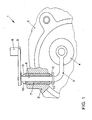
- FIG. 1 shows a valve device 1 of a turbocharger 2.
- the turbocharger 2 is schematically indicated in a section. A portion of the housing 3 of the turbocharger 2 is shown in section.
- the elements 4 to 9 of the valve device 1 are a valve disk 4, a valve lever 5, a valve axis 6, an axle bearing 7, an actuating device 8 and an actuating lever 9.
- the valve axis 6 is rotatably mounted in the axle bearing 7.
- the axle bearing 7 is shown here in the embodiment shown as an independent component. It is equally possible that the axle bearing 7 is an integral part of the housing 3 and formed integrally therewith.
- valve disk 4 is movable by means of the valve lever 5 of the valve axis 6 and the actuating device 8 is connected in the embodiment shown by means of an actuating lever 9 with the valve axis 6.
- the valve axis 6, the valve lever 5 and the actuating lever 8 are immovable relative to each other.
- a damping element 10 is arranged between the elements 5 and 7 or between the elements 7 and 9 of the valve device 1.
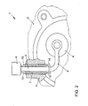
- FIG. 2 shows a further embodiment of in FIG. 1
- the actuator 8 is directly connected to the valve axis 6, wherein the actuator 8 and the valve axis 6 are rotatable relative to each other.
- the damping element 10 is arranged between the elements 5 and 7 or between the elements 7 and 8 of the valve device 1.
- FIG. 3 shows a schematic representation of the in FIG. 1
- the damping element 10 is located on the valve lever 5, on the valve axis 6, on the axle 7 and on the operating lever 9 freely movable.
- FIG. 4 shows a schematic representation of the in FIG. 1
- the damping element 10 is positively connected to the valve axis 6.
- the valve axis 6 has on both sides in each case a circumferential groove 11 into which a hook 12 of the damping element 10 engages.
- the damping element 10 is located on the axle bearing 7 freely movable.
- the damping element 10 consists of two annular spring elements which are arranged on both sides of the axle 7.
- FIG. 5 shows a schematic representation of a development of in FIG. 4
- the damping element 10 consists of only one annular spring element, which is positively connected to the valve axis 6 and the axle 7.
- the valve axis 6 has a circumferential groove 11 into which a hook 12 of the damping element 10 engages.
- the damping element 10 and the axle bearing 7 are connected via a connecting means:
- the connecting means may be a bond, a rivet, a weld or, as indicated, a screw 13. Due to the fixed connection of the damping element 10 with both elements 6, 7 of the valve device 1, the one-sided arrangement of only one spring element is sufficient, since such a set damping element 10 receives axial vibrations from both directions.
- FIG. 6 shows a schematic representation of a section of the in FIG. 1
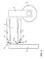
- the valve plate 4 comprises a bolt 14 with a rim 15 and a plate 16.
- the pin 14 of the valve lever 5 is free to move.
- the mobility of the valve lever 5 is limited by the plate 16 and the rim 15.
- a freely movable damping element 10 is arranged on both sides of the valve lever 5.
- the damping element 10 consists of annular non-prestressed spring elements, both of which rest against the valve lever and of which one rests against the rim 15 and the other on the plate 16.
- FIGS. 7 and 8 show a schematic representation of a development of in FIG. 6
- This seventh and eighth embodiment each have a damping element 10 each having only one spring element.
- the respective spring element is freely movable on the bolt.
- damping element 10 is applied to the valve lever 5 and the plate 16 at.
- FIG. 8 shows a damping element 10 which rests against the valve lever 5 and the brim 15.
- FIG. 9 shows a schematic representation of a development of in FIG. 6
- the mutually arranged on the valve lever 5 spring elements of the damping element 10 are freely movable on the bolt.
- the damping effect of the damping element 10 is achieved with respect to an axial vibration only when one of the spring elements has been moved to the brim 15 or to the plate 16.
- FIGS. 10 and 11 show a schematic representation of a development of in FIG. 6
- This tenth and eleventh embodiment each has a Damping element 10, each with only one spring element.
- the respective spring element has a hook 12 which engages in a circumferential groove 11 of the bolt 14.
- the valve lever 5 and the damping element 10 are preferably not connected to each other.
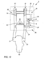
- the turbocharger 2 comprises a housing 3 indicated by a broken line, a compressor 17 and a turbine 18. Via a fresh gas inlet 19 fresh gas can flow from the atmosphere into the compressor 17. After the compressor 17, the fresh gas passes through a fresh gas line 20 to a fresh gas distribution 21 of an internal combustion engine 22. The exhaust gas from the engine 22 passes through an exhaust manifold 23 and an exhaust pipe 24 to the turbine 18. After the turbine 18, the exhaust gas flows through an exhaust outlet 25th into the atmosphere.
- the turbocharger 2 further has a boost pressure control device 26, which comprises a valve device 1 with an actuating device 8.
- the arrows 30 indicate the flow direction of fresh gas and exhaust gas.
- first embodiment of the wastegate 26 has a connected to the fresh gas line 20 pressure box 27.
- the pressure box 27 is connected to the actuator 8.
- the gas pressure in the fresh gas line 20 acts by means of the pressure box 27 and the actuator 8 on a valve plate 4 of the valve device. 1
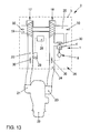
- FIG. 13 illustrated second embodiment of the wastegate 26 has an electronic control device 28 which is connected to a pressure sensor 29 and an electromechanical actuator 8.
- the control device 28 evaluates the gas pressure in the fresh gas line 20 detected at the pressure sensor 29 and activates the actuating device 8.
- the actuating device 8 acts on a valve disk 4 of the valve device 1 and adjusts it.
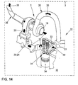
- FIG. 14 shows a schematic representation of an internal combustion engine 22 and one in the Figures 12 and 13
- the internal combustion engine 22 comprises at least one combustion chamber 31.
- the combustion chamber 31 is bounded by the inner surface of a cylinder 32 and by the facing surfaces of a cylinder head 33 and a movable piston 32 in the cylinder 32.
- the fresh gas is converted together with a fuel in exhaust gas.
- the piston 34 is moved in the cylinder 32. This mechanical kinetic energy is used, for example, to drive an in FIG. 15 shown vehicle 35 used.
- the fresh gas entering the internal combustion engine 22 passes through a fresh gas distribution 21 into the combustion chamber 31 via an exhaust manifold 23, the exhaust gas from the combustion chamber 31 and from the internal combustion engine 22 is passed.
- the turbocharger 2 is connected to the engine 22.
- the engine 22 and the turbocharger 2 form a common assembly as a unitary item of merchandise.
- the mechanical connection of turbocharger 2 and internal combustion engine 22 is possible by means of a flange.
- the turbocharger 2 and the engine 22 are arranged in a common housing 3.
- the housing 3 is indicated by a broken line.
- the fresh gas line 20 of the turbocharger 2 is connected to the fresh gas distribution 21 of the engine 22 and the exhaust pipe 24 of the turbocharger 2 and the exhaust manifold 23 of the engine 22 are made in one piece.
- the fresh gas inlet 19 and the exhaust gas outlet 25 are in the Figures 12 and 13 described.
- the flow direction of fresh gas and exhaust gas is indicated by the arrows 30.
- FIG. 15 shows a schematic representation of a vehicle 35, with a in the Figures 12 . 13 and 14 shown internal combustion engine 22 is equipped.
- the vehicle 35 has a front compartment 36, a rear compartment 37 and a passenger compartment 38.
- the internal combustion engine 22 is positioned in the rear compartment 37 or usually in the front compartment 36.
Landscapes
- Engineering & Computer Science (AREA)
- Chemical & Material Sciences (AREA)
- Combustion & Propulsion (AREA)
- Mechanical Engineering (AREA)
- General Engineering & Computer Science (AREA)
- Supercharger (AREA)
Applications Claiming Priority (1)
| Application Number | Priority Date | Filing Date | Title |
|---|---|---|---|
| DE102011111817A DE102011111817A1 (de) | 2011-08-27 | 2011-08-27 | Ventileinrichtung, Turbolader mit Ventileinrichtung, Brennkraftmaschine mit Turbolader und Fahrzeug mit Brennkraftmaschine |
Publications (4)
| Publication Number | Publication Date |
|---|---|
| EP2574754A2 true EP2574754A2 (fr) | 2013-04-03 |
| EP2574754A8 EP2574754A8 (fr) | 2013-11-27 |
| EP2574754A3 EP2574754A3 (fr) | 2014-05-14 |
| EP2574754B1 EP2574754B1 (fr) | 2017-05-03 |
Family
ID=46798962
Family Applications (1)
| Application Number | Title | Priority Date | Filing Date |
|---|---|---|---|
| EP12006014.0A Not-in-force EP2574754B1 (fr) | 2011-08-27 | 2012-08-23 | Dispositif de soupape, turbosoufflante avec dispositif de soupape, moteur à combustion avec turbosoufflante et véhicule automobile avec moteur à combustion |
Country Status (2)
| Country | Link |
|---|---|
| EP (1) | EP2574754B1 (fr) |
| DE (1) | DE102011111817A1 (fr) |
Cited By (8)
| Publication number | Priority date | Publication date | Assignee | Title |
|---|---|---|---|---|
| WO2014121986A1 (fr) * | 2013-02-05 | 2014-08-14 | Volkswagen Aktiengesellschaft | Unité soupape pour un système wastegate et turbocompresseur à gaz d'échappement |
| US9249721B2 (en) | 2014-03-03 | 2016-02-02 | Honeywell International Inc. | Turbocharger turbine wastegate mechanism |
| US9638099B2 (en) | 2014-03-03 | 2017-05-02 | Honeywell International Inc. | Turbocharger turbine wastegate mechanism |
| US20180023462A1 (en) * | 2016-07-24 | 2018-01-25 | Honeywell International Inc. | Turbine wastegate |
| US20180045105A1 (en) * | 2016-07-24 | 2018-02-15 | Honeywell International Inc. | Turbocharger turbine wastegate assembly |
| JPWO2017212805A1 (ja) * | 2016-06-07 | 2018-10-25 | 株式会社Ihi | 流量可変バルブ機構及び過給機 |
| US10215088B2 (en) | 2016-07-24 | 2019-02-26 | Garrett Transporation I Inc. | Method of assembling a turbine wastegate assembly |
| US10570815B2 (en) | 2017-10-19 | 2020-02-25 | Garrett Transportation I Inc. | Wastegate valve assembly with biasing members |
Families Citing this family (1)
| Publication number | Priority date | Publication date | Assignee | Title |
|---|---|---|---|---|
| DE102016002269B4 (de) * | 2016-02-26 | 2021-08-26 | Feinguss Blank Gmbh | Ventilelement |
Citations (3)
| Publication number | Priority date | Publication date | Assignee | Title |
|---|---|---|---|---|
| WO2005008041A1 (fr) | 2003-07-11 | 2005-01-27 | Malcolm George Leavesley | Appareil turbocompresseur presentant un systeme d'etancheite de gaz d'echappement permettant d'eliminer des fuites de gaz provenant de l'appareil turbocompresseur |
| DE102006021185A1 (de) | 2006-05-06 | 2007-11-22 | Bayerische Motoren Werke Ag | Verschlussklappe für einen Abgasturbolader |
| WO2010135104A2 (fr) | 2009-05-18 | 2010-11-25 | Borgwarner Inc. | Turbocompresseur |
Family Cites Families (10)
| Publication number | Priority date | Publication date | Assignee | Title |
|---|---|---|---|---|
| DE1926338A1 (de) * | 1969-05-23 | 1970-12-17 | Motoren Turbinen Union | Vorrichtung zur Lagerung schwenkbarer Leitschaufeln von thermischen Turbomaschinen |
| JPS6133923U (ja) * | 1984-07-31 | 1986-03-01 | 三菱自動車工業株式会社 | 可変容量タ−ボ過給装置 |
| DE9416775U1 (de) * | 1994-10-18 | 1994-12-08 | Reinz-Dichtungs-Gmbh, 89233 Neu-Ulm | Dämpfungsvorrichtung |
| JPH08334030A (ja) * | 1995-06-06 | 1996-12-17 | Aisan Ind Co Ltd | ターボ・チャージャのウェイスト・ゲート・バルブ |
| JP4415693B2 (ja) * | 2004-02-16 | 2010-02-17 | 株式会社Ihi | 過給機 |
| US20070204616A1 (en) * | 2006-03-06 | 2007-09-06 | Honeywell International, Inc. | Swing valve for a turbocharger with stacked valve members, and two-stage turbocharger system incorporating same |
| DE102007018618A1 (de) * | 2006-04-19 | 2007-10-25 | Borgwarner Inc., Auburn Hills | Turbolader |
| DE102009050182A1 (de) * | 2009-10-21 | 2011-05-05 | Bayerische Motoren Werke Aktiengesellschaft | Abgasturboladergehäuse mit einem verschließbaren Strömungskanal |
| DE202009015888U1 (de) * | 2009-11-20 | 2010-02-25 | Bosch Mahle Turbo Systems Gmbh & Co. Kg | Dichtanordnung einer Welle |
| DE102010043147A1 (de) * | 2010-04-27 | 2011-10-27 | Bosch Mahle Turbo Systems Gmbh & Co. Kg | Ladeeinrichtung |
-
2011
- 2011-08-27 DE DE102011111817A patent/DE102011111817A1/de not_active Withdrawn
-
2012
- 2012-08-23 EP EP12006014.0A patent/EP2574754B1/fr not_active Not-in-force
Patent Citations (3)
| Publication number | Priority date | Publication date | Assignee | Title |
|---|---|---|---|---|
| WO2005008041A1 (fr) | 2003-07-11 | 2005-01-27 | Malcolm George Leavesley | Appareil turbocompresseur presentant un systeme d'etancheite de gaz d'echappement permettant d'eliminer des fuites de gaz provenant de l'appareil turbocompresseur |
| DE102006021185A1 (de) | 2006-05-06 | 2007-11-22 | Bayerische Motoren Werke Ag | Verschlussklappe für einen Abgasturbolader |
| WO2010135104A2 (fr) | 2009-05-18 | 2010-11-25 | Borgwarner Inc. | Turbocompresseur |
Cited By (10)
| Publication number | Priority date | Publication date | Assignee | Title |
|---|---|---|---|---|
| WO2014121986A1 (fr) * | 2013-02-05 | 2014-08-14 | Volkswagen Aktiengesellschaft | Unité soupape pour un système wastegate et turbocompresseur à gaz d'échappement |
| US9249721B2 (en) | 2014-03-03 | 2016-02-02 | Honeywell International Inc. | Turbocharger turbine wastegate mechanism |
| US9638099B2 (en) | 2014-03-03 | 2017-05-02 | Honeywell International Inc. | Turbocharger turbine wastegate mechanism |
| JPWO2017212805A1 (ja) * | 2016-06-07 | 2018-10-25 | 株式会社Ihi | 流量可変バルブ機構及び過給機 |
| US20180023462A1 (en) * | 2016-07-24 | 2018-01-25 | Honeywell International Inc. | Turbine wastegate |
| US20180045105A1 (en) * | 2016-07-24 | 2018-02-15 | Honeywell International Inc. | Turbocharger turbine wastegate assembly |
| US10215088B2 (en) | 2016-07-24 | 2019-02-26 | Garrett Transporation I Inc. | Method of assembling a turbine wastegate assembly |
| US10227916B2 (en) * | 2016-07-24 | 2019-03-12 | Garrett Transportation I Inc. | Turbocharger turbine wastegate assembly |
| US10233827B2 (en) * | 2016-07-24 | 2019-03-19 | Garrett Transportation I Inc. | Turbine wastegate |
| US10570815B2 (en) | 2017-10-19 | 2020-02-25 | Garrett Transportation I Inc. | Wastegate valve assembly with biasing members |
Also Published As
| Publication number | Publication date |
|---|---|
| EP2574754B1 (fr) | 2017-05-03 |
| EP2574754A3 (fr) | 2014-05-14 |
| DE102011111817A1 (de) | 2013-02-28 |
| EP2574754A8 (fr) | 2013-11-27 |
Similar Documents
| Publication | Publication Date | Title |
|---|---|---|
| EP2574754B1 (fr) | Dispositif de soupape, turbosoufflante avec dispositif de soupape, moteur à combustion avec turbosoufflante et véhicule automobile avec moteur à combustion | |
| EP2951402B1 (fr) | Turbocompresseur à gaz d'échappement présentant une connection sans usure des composants du system wastegate | |
| EP1826391A2 (fr) | Dispositif de recyclage des gaz d'échappement | |
| DE102016100900A1 (de) | Verstellvorrichtung für einen Abgasturbolader und Abgasturbolader | |
| DE102008010658A1 (de) | Abgasregelsystem und Abgasregelverfahren | |
| DE112013002306T5 (de) | Abgasturbolader | |
| DE102009048125A1 (de) | Wastegate-Anordnung für eine Turbine, Turbine für einen Abgasturbolader, Abgasturbolader, Kraftfahrzeug und Verfahren zum Betreiben eines Abgasturboladers | |
| EP2726719A1 (fr) | Dispositif à soupape destiné à réguler un flux de gaz d'échappement d'un moteur à combustion interne | |
| DE102009051623A1 (de) | Stelleinrichtung für eine Ventilklappe | |
| DE102013209755A1 (de) | Ventilvorrichtung | |
| DE102010050669A1 (de) | Gehäuse für ein Laufrad | |
| DE102011101948A1 (de) | Ventilklappenvorrichtung | |
| DE102014116974A1 (de) | EGR-Steuerventilvorrichtung | |
| WO2012146510A2 (fr) | Appareil de charge | |
| EP2749761B1 (fr) | Conduite de fluide d'un moteur à combustion interne avec soupape pour le réglage d'un débit massique de fluide et moteur à combustion interne | |
| DE10149287B9 (de) | Abgas-Turbolader für eine Brennkraftmaschine mit einer schaltbaren Abgas-Turbolader-Anordnung | |
| DE102016100901A1 (de) | Verstellvorrichtung für einen Abgasturbolader und Abgasturbolader | |
| DE102017119958A1 (de) | Ventilbaugruppe und diese umfassendes ventilsystem | |
| DE102011117339B4 (de) | Abgasturbolader mit einem Wastegate-Ventil | |
| EP2573357A1 (fr) | Soupape de décharge à turbocompresseur | |
| EP1359300B1 (fr) | Unité de vanne d'étranglement | |
| DE102011078907A1 (de) | Vervollkommnetes Ventil und Anwendung | |
| DE102013200225A1 (de) | Verbindungsvorrichtung | |
| EP1746263B1 (fr) | Système de soupape pour un échangeur de chaleur | |
| DE102005041146A1 (de) | Ventil, insbesondere Drehkolbenventil, und Abgasrückführsystem mit einem solchen Ventil |
Legal Events
| Date | Code | Title | Description |
|---|---|---|---|
| PUAI | Public reference made under article 153(3) epc to a published international application that has entered the european phase |
Free format text: ORIGINAL CODE: 0009012 |
|
| AK | Designated contracting states |
Kind code of ref document: A2 Designated state(s): AL AT BE BG CH CY CZ DE DK EE ES FI FR GB GR HR HU IE IS IT LI LT LU LV MC MK MT NL NO PL PT RO RS SE SI SK SM TR |
|
| AX | Request for extension of the european patent |
Extension state: BA ME |
|
| RIN1 | Information on inventor provided before grant (corrected) |
Inventor name: KUENSTNER, MARKO |
|
| PUAL | Search report despatched |
Free format text: ORIGINAL CODE: 0009013 |
|
| AK | Designated contracting states |
Kind code of ref document: A3 Designated state(s): AL AT BE BG CH CY CZ DE DK EE ES FI FR GB GR HR HU IE IS IT LI LT LU LV MC MK MT NL NO PL PT RO RS SE SI SK SM TR |
|
| AX | Request for extension of the european patent |
Extension state: BA ME |
|
| RIC1 | Information provided on ipc code assigned before grant |
Ipc: F02B 37/18 20060101AFI20140404BHEP |
|
| 17P | Request for examination filed |
Effective date: 20141114 |
|
| RBV | Designated contracting states (corrected) |
Designated state(s): AL AT BE BG CH CY CZ DE DK EE ES FI FR GB GR HR HU IE IS IT LI LT LU LV MC MK MT NL NO PL PT RO RS SE SI SK SM TR |
|
| 17Q | First examination report despatched |
Effective date: 20150422 |
|
| GRAP | Despatch of communication of intention to grant a patent |
Free format text: ORIGINAL CODE: EPIDOSNIGR1 |
|
| INTG | Intention to grant announced |
Effective date: 20161220 |
|
| GRAS | Grant fee paid |
Free format text: ORIGINAL CODE: EPIDOSNIGR3 |
|
| GRAA | (expected) grant |
Free format text: ORIGINAL CODE: 0009210 |
|
| AK | Designated contracting states |
Kind code of ref document: B1 Designated state(s): AL AT BE BG CH CY CZ DE DK EE ES FI FR GB GR HR HU IE IS IT LI LT LU LV MC MK MT NL NO PL PT RO RS SE SI SK SM TR |
|
| REG | Reference to a national code |
Ref country code: GB Ref legal event code: FG4D Free format text: NOT ENGLISH |
|
| REG | Reference to a national code |
Ref country code: AT Ref legal event code: REF Ref document number: 890267 Country of ref document: AT Kind code of ref document: T Effective date: 20170515 Ref country code: CH Ref legal event code: EP |
|
| REG | Reference to a national code |
Ref country code: IE Ref legal event code: FG4D Free format text: LANGUAGE OF EP DOCUMENT: GERMAN |
|
| REG | Reference to a national code |
Ref country code: DE Ref legal event code: R096 Ref document number: 502012010208 Country of ref document: DE |
|
| REG | Reference to a national code |
Ref country code: FR Ref legal event code: PLFP Year of fee payment: 6 |
|
| REG | Reference to a national code |
Ref country code: NL Ref legal event code: MP Effective date: 20170503 |
|
| REG | Reference to a national code |
Ref country code: LT Ref legal event code: MG4D |
|
| PG25 | Lapsed in a contracting state [announced via postgrant information from national office to epo] |
Ref country code: ES Free format text: LAPSE BECAUSE OF FAILURE TO SUBMIT A TRANSLATION OF THE DESCRIPTION OR TO PAY THE FEE WITHIN THE PRESCRIBED TIME-LIMIT Effective date: 20170503 Ref country code: LT Free format text: LAPSE BECAUSE OF FAILURE TO SUBMIT A TRANSLATION OF THE DESCRIPTION OR TO PAY THE FEE WITHIN THE PRESCRIBED TIME-LIMIT Effective date: 20170503 Ref country code: HR Free format text: LAPSE BECAUSE OF FAILURE TO SUBMIT A TRANSLATION OF THE DESCRIPTION OR TO PAY THE FEE WITHIN THE PRESCRIBED TIME-LIMIT Effective date: 20170503 Ref country code: FI Free format text: LAPSE BECAUSE OF FAILURE TO SUBMIT A TRANSLATION OF THE DESCRIPTION OR TO PAY THE FEE WITHIN THE PRESCRIBED TIME-LIMIT Effective date: 20170503 Ref country code: NO Free format text: LAPSE BECAUSE OF FAILURE TO SUBMIT A TRANSLATION OF THE DESCRIPTION OR TO PAY THE FEE WITHIN THE PRESCRIBED TIME-LIMIT Effective date: 20170803 Ref country code: GR Free format text: LAPSE BECAUSE OF FAILURE TO SUBMIT A TRANSLATION OF THE DESCRIPTION OR TO PAY THE FEE WITHIN THE PRESCRIBED TIME-LIMIT Effective date: 20170804 |
|
| PGFP | Annual fee paid to national office [announced via postgrant information from national office to epo] |
Ref country code: GB Payment date: 20170830 Year of fee payment: 6 Ref country code: FR Payment date: 20170828 Year of fee payment: 6 Ref country code: DE Payment date: 20170831 Year of fee payment: 6 |
|
| PG25 | Lapsed in a contracting state [announced via postgrant information from national office to epo] |
Ref country code: RS Free format text: LAPSE BECAUSE OF FAILURE TO SUBMIT A TRANSLATION OF THE DESCRIPTION OR TO PAY THE FEE WITHIN THE PRESCRIBED TIME-LIMIT Effective date: 20170503 Ref country code: BG Free format text: LAPSE BECAUSE OF FAILURE TO SUBMIT A TRANSLATION OF THE DESCRIPTION OR TO PAY THE FEE WITHIN THE PRESCRIBED TIME-LIMIT Effective date: 20170803 Ref country code: LV Free format text: LAPSE BECAUSE OF FAILURE TO SUBMIT A TRANSLATION OF THE DESCRIPTION OR TO PAY THE FEE WITHIN THE PRESCRIBED TIME-LIMIT Effective date: 20170503 Ref country code: SE Free format text: LAPSE BECAUSE OF FAILURE TO SUBMIT A TRANSLATION OF THE DESCRIPTION OR TO PAY THE FEE WITHIN THE PRESCRIBED TIME-LIMIT Effective date: 20170503 Ref country code: PL Free format text: LAPSE BECAUSE OF FAILURE TO SUBMIT A TRANSLATION OF THE DESCRIPTION OR TO PAY THE FEE WITHIN THE PRESCRIBED TIME-LIMIT Effective date: 20170503 Ref country code: NL Free format text: LAPSE BECAUSE OF FAILURE TO SUBMIT A TRANSLATION OF THE DESCRIPTION OR TO PAY THE FEE WITHIN THE PRESCRIBED TIME-LIMIT Effective date: 20170503 Ref country code: IS Free format text: LAPSE BECAUSE OF FAILURE TO SUBMIT A TRANSLATION OF THE DESCRIPTION OR TO PAY THE FEE WITHIN THE PRESCRIBED TIME-LIMIT Effective date: 20170903 |
|
| PG25 | Lapsed in a contracting state [announced via postgrant information from national office to epo] |
Ref country code: CZ Free format text: LAPSE BECAUSE OF FAILURE TO SUBMIT A TRANSLATION OF THE DESCRIPTION OR TO PAY THE FEE WITHIN THE PRESCRIBED TIME-LIMIT Effective date: 20170503 Ref country code: DK Free format text: LAPSE BECAUSE OF FAILURE TO SUBMIT A TRANSLATION OF THE DESCRIPTION OR TO PAY THE FEE WITHIN THE PRESCRIBED TIME-LIMIT Effective date: 20170503 Ref country code: SK Free format text: LAPSE BECAUSE OF FAILURE TO SUBMIT A TRANSLATION OF THE DESCRIPTION OR TO PAY THE FEE WITHIN THE PRESCRIBED TIME-LIMIT Effective date: 20170503 Ref country code: EE Free format text: LAPSE BECAUSE OF FAILURE TO SUBMIT A TRANSLATION OF THE DESCRIPTION OR TO PAY THE FEE WITHIN THE PRESCRIBED TIME-LIMIT Effective date: 20170503 Ref country code: RO Free format text: LAPSE BECAUSE OF FAILURE TO SUBMIT A TRANSLATION OF THE DESCRIPTION OR TO PAY THE FEE WITHIN THE PRESCRIBED TIME-LIMIT Effective date: 20170503 |
|
| REG | Reference to a national code |
Ref country code: DE Ref legal event code: R097 Ref document number: 502012010208 Country of ref document: DE |
|
| PG25 | Lapsed in a contracting state [announced via postgrant information from national office to epo] |
Ref country code: SM Free format text: LAPSE BECAUSE OF FAILURE TO SUBMIT A TRANSLATION OF THE DESCRIPTION OR TO PAY THE FEE WITHIN THE PRESCRIBED TIME-LIMIT Effective date: 20170503 Ref country code: IT Free format text: LAPSE BECAUSE OF FAILURE TO SUBMIT A TRANSLATION OF THE DESCRIPTION OR TO PAY THE FEE WITHIN THE PRESCRIBED TIME-LIMIT Effective date: 20170503 |
|
| PLBE | No opposition filed within time limit |
Free format text: ORIGINAL CODE: 0009261 |
|
| STAA | Information on the status of an ep patent application or granted ep patent |
Free format text: STATUS: NO OPPOSITION FILED WITHIN TIME LIMIT |
|
| REG | Reference to a national code |
Ref country code: CH Ref legal event code: PL |
|
| PG25 | Lapsed in a contracting state [announced via postgrant information from national office to epo] |
Ref country code: MC Free format text: LAPSE BECAUSE OF FAILURE TO SUBMIT A TRANSLATION OF THE DESCRIPTION OR TO PAY THE FEE WITHIN THE PRESCRIBED TIME-LIMIT Effective date: 20170503 |
|
| 26N | No opposition filed |
Effective date: 20180206 |
|
| PG25 | Lapsed in a contracting state [announced via postgrant information from national office to epo] |
Ref country code: LI Free format text: LAPSE BECAUSE OF NON-PAYMENT OF DUE FEES Effective date: 20170831 Ref country code: CH Free format text: LAPSE BECAUSE OF NON-PAYMENT OF DUE FEES Effective date: 20170831 |
|
| REG | Reference to a national code |
Ref country code: IE Ref legal event code: MM4A |
|
| PG25 | Lapsed in a contracting state [announced via postgrant information from national office to epo] |
Ref country code: SI Free format text: LAPSE BECAUSE OF FAILURE TO SUBMIT A TRANSLATION OF THE DESCRIPTION OR TO PAY THE FEE WITHIN THE PRESCRIBED TIME-LIMIT Effective date: 20170503 |
|
| REG | Reference to a national code |
Ref country code: BE Ref legal event code: MM Effective date: 20170831 |
|
| PG25 | Lapsed in a contracting state [announced via postgrant information from national office to epo] |
Ref country code: LU Free format text: LAPSE BECAUSE OF NON-PAYMENT OF DUE FEES Effective date: 20170823 |
|
| PG25 | Lapsed in a contracting state [announced via postgrant information from national office to epo] |
Ref country code: IE Free format text: LAPSE BECAUSE OF NON-PAYMENT OF DUE FEES Effective date: 20170823 |
|
| PG25 | Lapsed in a contracting state [announced via postgrant information from national office to epo] |
Ref country code: BE Free format text: LAPSE BECAUSE OF NON-PAYMENT OF DUE FEES Effective date: 20170831 |
|
| PG25 | Lapsed in a contracting state [announced via postgrant information from national office to epo] |
Ref country code: MT Free format text: LAPSE BECAUSE OF FAILURE TO SUBMIT A TRANSLATION OF THE DESCRIPTION OR TO PAY THE FEE WITHIN THE PRESCRIBED TIME-LIMIT Effective date: 20170503 |
|
| REG | Reference to a national code |
Ref country code: AT Ref legal event code: MM01 Ref document number: 890267 Country of ref document: AT Kind code of ref document: T Effective date: 20170823 |
|
| PG25 | Lapsed in a contracting state [announced via postgrant information from national office to epo] |
Ref country code: AT Free format text: LAPSE BECAUSE OF NON-PAYMENT OF DUE FEES Effective date: 20170823 |
|
| REG | Reference to a national code |
Ref country code: DE Ref legal event code: R119 Ref document number: 502012010208 Country of ref document: DE |
|
| GBPC | Gb: european patent ceased through non-payment of renewal fee |
Effective date: 20180823 |
|
| PG25 | Lapsed in a contracting state [announced via postgrant information from national office to epo] |
Ref country code: HU Free format text: LAPSE BECAUSE OF FAILURE TO SUBMIT A TRANSLATION OF THE DESCRIPTION OR TO PAY THE FEE WITHIN THE PRESCRIBED TIME-LIMIT; INVALID AB INITIO Effective date: 20120823 |
|
| PG25 | Lapsed in a contracting state [announced via postgrant information from national office to epo] |
Ref country code: DE Free format text: LAPSE BECAUSE OF NON-PAYMENT OF DUE FEES Effective date: 20190301 |
|
| PG25 | Lapsed in a contracting state [announced via postgrant information from national office to epo] |
Ref country code: FR Free format text: LAPSE BECAUSE OF NON-PAYMENT OF DUE FEES Effective date: 20180831 |
|
| PG25 | Lapsed in a contracting state [announced via postgrant information from national office to epo] |
Ref country code: GB Free format text: LAPSE BECAUSE OF NON-PAYMENT OF DUE FEES Effective date: 20180823 Ref country code: CY Free format text: LAPSE BECAUSE OF NON-PAYMENT OF DUE FEES Effective date: 20170503 |
|
| PG25 | Lapsed in a contracting state [announced via postgrant information from national office to epo] |
Ref country code: MK Free format text: LAPSE BECAUSE OF FAILURE TO SUBMIT A TRANSLATION OF THE DESCRIPTION OR TO PAY THE FEE WITHIN THE PRESCRIBED TIME-LIMIT Effective date: 20170503 |
|
| PG25 | Lapsed in a contracting state [announced via postgrant information from national office to epo] |
Ref country code: TR Free format text: LAPSE BECAUSE OF FAILURE TO SUBMIT A TRANSLATION OF THE DESCRIPTION OR TO PAY THE FEE WITHIN THE PRESCRIBED TIME-LIMIT Effective date: 20170503 |
|
| PG25 | Lapsed in a contracting state [announced via postgrant information from national office to epo] |
Ref country code: PT Free format text: LAPSE BECAUSE OF FAILURE TO SUBMIT A TRANSLATION OF THE DESCRIPTION OR TO PAY THE FEE WITHIN THE PRESCRIBED TIME-LIMIT Effective date: 20170503 |
|
| PG25 | Lapsed in a contracting state [announced via postgrant information from national office to epo] |
Ref country code: AL Free format text: LAPSE BECAUSE OF FAILURE TO SUBMIT A TRANSLATION OF THE DESCRIPTION OR TO PAY THE FEE WITHIN THE PRESCRIBED TIME-LIMIT Effective date: 20170503 |