EP2576144B1 - Elektrowerkzeug, insbesondere bohrschrauber - Google Patents
Elektrowerkzeug, insbesondere bohrschrauber Download PDFInfo
- Publication number
- EP2576144B1 EP2576144B1 EP11715503.6A EP11715503A EP2576144B1 EP 2576144 B1 EP2576144 B1 EP 2576144B1 EP 11715503 A EP11715503 A EP 11715503A EP 2576144 B1 EP2576144 B1 EP 2576144B1
- Authority
- EP
- European Patent Office
- Prior art keywords
- actuating element
- adjusting
- power tool
- electric power
- acts
- Prior art date
- Legal status (The legal status is an assumption and is not a legal conclusion. Google has not performed a legal analysis and makes no representation as to the accuracy of the status listed.)
- Not-in-force
Links
Images



Classifications
-
- B—PERFORMING OPERATIONS; TRANSPORTING
- B25—HAND TOOLS; PORTABLE POWER-DRIVEN TOOLS; MANIPULATORS
- B25F—COMBINATION OR MULTI-PURPOSE TOOLS NOT OTHERWISE PROVIDED FOR; DETAILS OR COMPONENTS OF PORTABLE POWER-DRIVEN TOOLS NOT PARTICULARLY RELATED TO THE OPERATIONS PERFORMED AND NOT OTHERWISE PROVIDED FOR
- B25F5/00—Details or components of portable power-driven tools not particularly related to the operations performed and not otherwise provided for
- B25F5/001—Gearings, speed selectors, clutches or the like specially adapted for rotary tools
-
- B—PERFORMING OPERATIONS; TRANSPORTING
- B25—HAND TOOLS; PORTABLE POWER-DRIVEN TOOLS; MANIPULATORS
- B25B—TOOLS OR BENCH DEVICES NOT OTHERWISE PROVIDED FOR, FOR FASTENING, CONNECTING, DISENGAGING, OR HOLDING
- B25B21/00—Portable power-driven screw or nut setting or loosening tools; Attachments for drilling apparatus serving the same purpose
Definitions
- the invention relates to a power tool, in particular a drill, according to the preamble of claim 1.
- a power tool is of EP 1 857 228 A1 known.
- a power tool is also from the DE 10 2004 051 911 A1 the applicant known.
- the power tool known therefrom has two adjusting rings designed as separate actuating elements, wherein the first adjusting ring for the operating mode "drilling" and “screws” with the possibility of setting a maximum torque to be transmitted, and the other adjusting ring for setting a Schlagbohrfunktion. From the operator are thus to set and change operating parameters in different modes of operation two separate actuators or collars to use, in each case only one of the actuators is effective. The operation therefore requires knowledge of the functionality of the two actuators. Furthermore, the known power tool is relatively complex constructed by the two collars and the arrangement of the two actuators requires a relatively large space.
- the present invention seeks to further develop a power tool, in particular a drill, according to the preamble of claim 1 such that its structure is simplified by a reduction of adjustment and the operator at the same time a relatively simple operation is possible ,
- This task is achieved in a power tool, in particular a drill, with the features of claim 1.
- the invention is based on the idea of actuating the two adjusting devices for the respective operating modes via a common actuating element. In other words, this means that two adjusting devices can be actuated in different operating modes by means of a single actuating element.
- a simplified construction compared to the prior art is made possible by a reduced number of components. At the same time the operation of the two adjustment is simplified.
- the invention has the advantage that can be possible by the saving of controls, a particularly compact design of the power tool, since only space for a single actuator is needed.
- Advantageous developments of the power tool according to the invention are specified in the subclaims.
- the actuating element is designed as a mechanical actuating element in the form of a sliding or rotary switch.
- the actuating element has a first adjustment, in which the actuating element exclusively with the first adjustment cooperates, and with a subsequent to the first adjustment second adjustment range, in which the actuating element cooperates exclusively with the second adjusting device.
- the first adjusting device for torque adjustment, a potentiometer for detecting the position of the actuating element, whose resistance value is variable by means of a contact element arranged on the actuating element and acting as a bridging between conductor tracks.
- the position of the actuating element is represented by means of an optical display.
- an optical display is relatively easily detectable by an operator and thus enables a particularly accurate adjustment of the desired switching position of the actuating element.
- optical display is arranged in the region of the adjustment path of a control element of the actuating element.
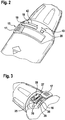
- an inventive power tool 10 is shown in the form of a battery-powered drill.
- the power tool 10 has, in a manner known per se, a drive motor 11, which acts on a drive spindle 13 via a gear 12.
- the transmission 12 of the power tool 10 at least two gear stages (not shown), of which the first gear stage, which has a higher reduction than the second gear stage, used for screwing, while the second gear stage is suitable for drilling. It is also essential that the maximum torque to be transmitted of the drive motor 11 to the drive spindle 13 can be set for the screwing function.
- actuating element 15 is in this case realized in the illustrated embodiment as a trained as a rotary ring 16 slide switch.
- the actuating element 15 could be formed instead of a rotary ring 16 as a rotary switch.
- the rotary ring 16 is adjustable in the housing of the drill 1 within a certain rotation angle range.
- the respective position of the operating element 17 or of the rotary ring 16 is displayed via a visual display 18.
- the optical display 18 comprises two separate display panels 19, 20, in which in particular a plurality of LEDs are arranged. It is essential here that in the one display field 19, the actuating element 15 is in the addressed first operating mode, in which the drill driver 1 allows a screwing, while the second display panel 20 is used to display the drilling operation.
- the arrangement of the display panels 19, 20 is such that the respective luminous LEDs are correlated or aligned with the position of the control element 17.
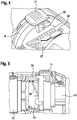
- the rotary ring 16 on its one end face on an electrically acting contact element 22 which is received positively on the rotary ring 16 in a preferably molded recess.
- the contact element 22 is part of a potentiometer 25 which is formed on an arcuate circuit board 26.
- the circuit board 26 is in turn connected to a circuit carrier 27, are arranged on the evaluation means 28 which are adapted to detect the position of the contact element 22 relative to the circuit board 26.
- the circuit board 26 has two conductor tracks 29, 30, which are arranged at a distance from one another and are electrically bridged by means of the contact element 22.
- the position or position of the contact element 22, and thus the rotational angular position of the rotary ring 16 is detected by the fact that according to the position of the rotary ring 16, the contact element 22 also occupies a position of the rotary ring 16 associated unique position.
- the contact element 22 bridges the two interconnects 29, 30 on the circuit board 26, so that the potentiometer 25 generates a very specific resistance, which is detected by means of the evaluation means 28.
- This detected value of the angular position of the rotary ring 16 is supplied by the evaluation means 28 to a control device of the power tool 10, not shown in the figures as an input value, which due to the position of the rotary ring 16, and possibly other additional input variables, the maximum torque to be transmitted Drive motor 1 by limiting the current of the drive motor 11 sets.
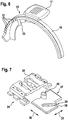
- locking cams 31 are formed on the rotary ring 16, which cooperate with a corresponding rotation of the rotary ring 16 with corresponding counter means, for example, in the housing and the operator on the one hand produce a tactile snapping when turning the rotary ring 16 and on the other a corresponding noise, which can be perceived by the operator.
- an adjusting element in the form of an adjusting pin 33 is integrally formed on the rotary ring 16, an adjusting element in the form of an adjusting pin 33 is integrally formed.
- the adjusting pin 33 is part of a Gangvor lightsschalters 34, corresponding to the Fig. 7 to 9
- a stationary in the power tool 10 arranged guide housing 35 comprises, in which a corresponding to the double arrow 36 perpendicular to the direction of rotation of the rotary ring 16, whose direction of rotation is indicated by the double arrow 32, slidably disposed transmission plate 37 is arranged.
- a guide groove 38 is formed for the adjustment pin 33, which is formed open at its one end 39.
- the transfer plate 37 has on its upper side on a locking cam 40 which cooperates with two, integrally formed on the guide housing 35 latching clips 44, 45.
- the locking cam 40 takes two according to the position in the transfer plate 37, in the 8 and 9 shown positions in which the transmission plate 37 by means of a transmission lever 37 coupled to the shift lever 41, the transmission 12 of the power tool 10 either in the first gear, which is intended for screwing, or in the second gear, which is suitable for drilling adjusts.
- the adjustment between the two positions that is, the respective overcoming the latching clip 44, 45 by the locking cam 40, the operator both haptically and acoustically perceptible.
- the operation of the Gangvoriansschalters 34 is as follows: in the position of the rotary ring 16, in which the contact element 22 is in the region of the tracks 29, 30 of the potentiometer 25, which is synonymous with a first adjustment range 42 (FIGS. Fig. 2 ) of the rotary ring 16 for the screwing mode, the adjusting pin 33 is disengaged from the guide groove 38 of the transmission plate 37. That is, the shift lever 41 assumes a position in which the transmission 12 of the power tool 10 is in first gear. Upon rotation of the rotary ring 16 over the range of the potentiometer 25, which is synonymous with a second adjustment 43, the adjustment pin 33 comes into engagement with the guide groove 38 of the transfer plate 37.
Landscapes
- Engineering & Computer Science (AREA)
- Mechanical Engineering (AREA)
- Drilling And Boring (AREA)
- Details Of Spanners, Wrenches, And Screw Drivers And Accessories (AREA)
- Portable Power Tools In General (AREA)
Description
- Die Erfindung betrifft ein Elektrowerkzeug, insbesondere einen Bohrschrauber, nach dem Oberbegriff des Anspruchs 1. Ein solches Elektrowerkzeug ist von
EP 1 857 228 A1 bekannt. - Ein Elektrowerkzeug ist auch aus der
DE 10 2004 051 911 A1 der Anmelderin bekannt. Das daraus bekannte Elektrowerkzeug weist dabei zwei als separate Betätigungselemente ausgebildete Stellringe auf, wobei der erste Stellring für den Betriebsmodus "Bohren" und "Schrauben" mit der Möglichkeit der Einstellung eines maximal zu übertragenden Drehmoments, und der andere Stellring zum Einstellen einer Schlagbohrfunktion dient. Vom Bediener sind somit zum Einstellen und Wechseln von Betriebsparametern in unterschiedlichen Betriebsarten zwei voneinander getrennte Betätigungselemente bzw. Stellringe zu bedienen, wobei jeweils nur eines der Betätigungselemente wirksam ist. Die Bedienung erfordert daher die Kenntnis der Funktionalität der beiden Betätigungselemente. Weiterhin ist das bekannte Elektrowerkzeug durch die beiden Stellringe relativ aufwändig aufgebaut und die Anordnung der beiden Betätigungselemente benötigt einen relativ großen Bauraum. - Ausgehend von dem dargestellten Stand der Technik liegt der Erfindung die Aufgabe zugrunde, ein Elektrowerkzeug, insbesondere einen Bohrschrauber, nach dem Oberbegriff des Anspruchs 1 derart weiterzubilden, dass dessen Aufbau durch eine Reduzierung von Verstellelementen vereinfacht wird und dem Bediener gleichzeitig eine relativ einfache Bedienung ermöglicht wird. Diese Aufgabe wird bei einem Elektrowerkzeug, insbesondere einem Bohrschrauber, mit den Merkmalen des Anspruchs 1 gelöst. Der Erfindung liegt dabei die Idee zugrunde, die beiden Verstelleinrichtungen für die jeweiligen Betriebsmodi über ein gemeinsames Betätigungselement zu betätigen. Mit anderen Worten gesagt bedeutet dies, dass mittels eines einzigen Betätigungselements zwei Verstelleinrichtungen in unterschiedlichen Betriebsmodi betätigbar sind. Dadurch wird gegenüber dem Stand der Technik ein vereinfachter Aufbau durch eine reduzierte Bauteileanzahl ermöglicht. Gleichzeitig wird die Bedienung der beiden Verstelleinrichtungen vereinfacht. Die Erfindung hat darüber den Vorteil, dass durch die Einsparung von Bedienungselementen sich ein besonders kompakter Aufbau des Elektrowerkzeugs ermöglichen lässt, da lediglich Bauraum für ein einziges Betätigungselement benötigt wird.
Vorteilhafte Weiterbildungen des erfindungsgemäßen Elektrowerkzeugs sind in den Unteransprüchen angegeben.
In einer konstruktiven Umsetzung der Erfindung, die eine hohe Robustheit des Elektrowerkzeugs, insbesondere des Betätigungselements, ermöglicht wird vorgeschlagen, dass das Betätigungselement als mechanisches Betätigungselement in Form eines Schiebe- oder Drehschalters ausgebildet ist.
Um einerseits eine eindeutige Zuordnung bei der Betätigung des Betätigungselements zu den einzelnen Verstelleinrichtungen zu ermöglichen, die darüber hinaus durch einen Bediener einfach zu verstehen ist, wird darüber hinaus vorgeschlagen, dass das Betätigungselement einen ersten Verstellbereich aufweist, in der das Betätigungselement ausschließlich mit der ersten Verstelleinrichtung zusammenwirkt, und mit einem sich an dem ersten Verstellbereich anschließenden zweiten Verstellbereich, in der das Betätigungselement ausschließlich mit der zweiten Verstelleinrichtung zusammenwirkt.
Um eine einfache und stufenlose Erkennung der Position des Betätigungselements für die erste Verstelleinrichtung zu ermöglichen, wird es in einer bevorzugten Ausführungsform der Erfindung vorgeschlagen, dass die erste Verstelleinrichtung zur Drehmomenteinstellung ein Potentiometer zur Erkennung der Position des Betätigungselements umfasst, dessen Widerstandswert mittels eines am Betätigungselement angeordneten, als Überbrückung zwischen Leiterbahnen wirkenden Kontaktelements veränderbar ist. - Bevorzugt ist weiterhin eine Ausführungsform, bei der die Stellung des Betätigungselements mittels einer optischen Anzeige dargestellt ist. Eine derartige optische Anzeige ist von einem Bediener relativ leicht erfassbar und ermöglicht somit eine besonders genaue Einstellung der gewünschten Schaltstellung des Betätigungselements.
- Besonders bevorzugt ist es hierbei, wenn die optische Anzeige im Bereich des Verstellwegs eines Bedienelements des Betätigungselements angeordnet ist.
- Weitere Vorteile, Merkmale und Einzelheiten der Erfindung ergeben sich aus der nachfolgenden Beschreibung bevorzugter Ausführungsbeispiele sowie anhand der Zeichnungen.
- Diese zeigen in:
- Fig. 1
- eine perspektivische Ansicht auf ein erfindungsgemäßes Elektrowerkzeug in Form eines Bohrschraubers,
- Fig. 2
- eine perspektivische Teilansicht auf den Bohrschrauber gemäß
Fig. 1 im Bereich dessen Betätigungselements, - Fig. 3 und Fig. 4
- eine perspektivische, teilweise geschnittene Ansicht des Elektrowerkzeugs im Bereich der ersten Verstelleinrichtung aus unterschiedlichen Perspektiven,
- Fig. 5
- einen Längsschnitt durch das Elektrowerkzeug im Bereich der Verstelleinrichtungen,
- Fig. 6
- eine perspektivische Ansicht eines Teils des als Verstellring ausgebildeten Betätigungselements,
- Fig. 7
- Einzelteile der zweiten Verstelleinrichtung in perspektivischer Ansicht,
- Fig. 8 und Fig. 9
- die zweite Verstelleinrichtung in moniertem Zustand in unterschiedlichen Betriebsstellungen und
- Fig. 10
- das Elektrowerkzeug im Bereich des Betätigungselements in der Bohrstellung des Betätigungselements in perspektivischer Ansicht.
- In den Figuren sind gleiche Bauteile bzw. Bauteile mit gleicher Funktion mit jeweils identischen Bezugsziffern versehen.
- In der
Fig. 1 ist ein erfindungsgemäßes Elektrowerkzeug 10 in Form eines akkubetriebenen Bohrschraubers 1 dargestellt. Das Elektrowerkzeug 10 weist in an sich bekannter Art und Weise einen Antriebsmotor 11 auf, der über ein Getriebe 12 auf eine Antriebsspindel 13 wirkt. Ferner weist das Getriebe 12 des Elektrowerkzeugs 10 wenigstens zwei Getriebestufen (nicht dargestellt) auf, wovon die erste Getriebestufe, welche eine höhere Untersetzung aufweist als die zweite Getriebestufe, zum Schrauben Verwendung findet, während die zweite Getriebestufe zum Bohren geeignet ist. Wesentlich ist noch, dass für die Schraubfunktion das maximal zu übertragende Drehmoment des Antriebsmotors 11 auf die Antriebsspindel 13 einstellbar ist. - Erfindungsgemäß ist es vorgesehen, dass sowohl die Einstellung des zu übertragenden, maximalen Drehmoments während des Schraubbetriebs, als auch der Gangwechsel, der zum Umstellen vom Schraub- in den Bohrbetrieb erforderlich ist, mittels eines einzigen Betätigungselements 15 erfolgt. Das Betätigungselement 15 ist hierbei im dargestellten Ausführungsbeispiel als ein als Drehring 16 ausgebildeter Schiebeschalter realisiert. Ergänzend wird erwähnt, dass das Betätigungselement 15 anstelle als Drehring 16 auch als Drehschalter ausgebildet sein könnte.
- Der Drehring 16 ist im Gehäuse des Bohrschraubers 1 innerhalb eines bestimmten Drehwinkelbereichs verstellbar. Hierzu dient ein von außen vom Bediener betätigbares Bedienelement 17, das innerhalb des Verstellbereichs bzw. des Drehwinkelbereichs des Drehrings 16 vorzugsweise stufenlos verstellbar ist. Die jeweilige Stellung des Bedienelements 17 bzw. des Drehrings 16 wird über eine optische Anzeige 18 angezeigt. Dabei umfasst die optische Anzeige 18 zwei voneinander getrennt angeordnete Anzeigefelder 19, 20, in denen insbesondere eine Vielzahl von LEDs angeordnet sind. Wesentlich hierbei ist, dass in dem einen Anzeigefeld 19 sich das Betätigungselement 15 im angesprochenen ersten Betriebsmodus befindet, in der der Bohrschrauber 1 einen Schraubbetrieb ermöglicht, während das zweite Anzeigefeld 20 zur Anzeige des Bohrbetriebs dient. Die Anordnung der Anzeigefelder 19, 20 ist derart, dass die jeweils leuchtenden LEDs mit der Stellung des Bedienelements 17 korrelieren bzw. ausgerichtet sind.
- Wie insbesondere aus den
Fig. 3 und4 erkennbar ist, weist der Drehring 16 an seiner einen Stirnseite ein elektrisch wirkendes Kontaktelement 22 auf, das an dem Drehring 16 in einer vorzugsweise angespritzten Aussparung formschlüssig aufgenommen ist. Das Kontaktelement 22 ist Bestandteil eines Potentiometers 25, das an einer bogenförmigen Schaltplatine 26 ausgebildet ist. Die Schaltplatine 26 ist wiederum mit einem Schaltungsträger 27 verbunden, auf dem Auswertemittel 28 angeordnet sind, die dazu geeignet sind, die Stellung des Kontaktelements 22 relativ zur Schaltplatine 26 zu erfassen. Hierzu weist die Schaltplatine 26 zwei Leiterbahnen 29, 30 auf, die beabstandet zueinander angeordnet sind und mittels des Kontaktelements 22 elektrisch überbrückt werden. Die Stellung bzw. Position des Kontaktelements 22, und somit die Drehwinkelposition des Drehrings 16, wird dadurch erfasst, dass entsprechend der Position des Drehrings 16 das Kontaktelement 22 ebenfalls eine der Position des Drehrings 16 zugeordnete eindeutige Position einnimmt. Dabei überbrückt das Kontaktelement 22 die beiden Leiterbahnen 29, 30 an der Schaltplatine 26, so dass das Potentiometer 25 einen ganz bestimmten Widerstandswert erzeugt, der mittels der Auswertemittel 28 erfasst wird. Dieser erfasste Wert der Drehwinkelstellung des Drehrings 16 wird von den Auswertemitteln 28 an eine in den Figuren nicht dargestellte Steuereinrichtung des Elektrowerkzeugs 10 als Eingangswert zugeführt, welche aufgrund der Position des Drehrings 16, sowie ggf. anhand anderer zusätzlicher Eingangsgrößen, das maximal zu übertragene Drehmoment des Antriebsmotors 1 durch eine Begrenzung des Stromes des Antriebsmotors 11 einstellt. - In der
Fig. 6 erkennt man die dem Kontaktelement 22 gegenüberliegende Stirnseite des Drehrings 16. Hierbei sind Rastnocken 31 am Drehring 16 angeformt, die bei einer Drehung des Drehrings 16 mit entsprechenden Gegenmitteln zum Beispiel im Gehäuse zusammenwirken und beim Bediener einerseits ein haptisch fühlbares Einrasten beim Drehen des Drehrings 16 erzeugen und zum anderen ein entsprechendes Geräusch, welches vom Bediener wahrgenommen werden kann. - Darüber hinaus erkennt man, dass an dem Drehring 16 ein Verstellelement in Form eines Verstellzapfens 33 angeformt ist. Der Verstellzapfen 33 ist Bestandteil eines Gangvorwahlschalters 34, der entsprechend den
Fig. 7 bis 9 ein ortsfest im Elektrowerkzeug 10 angeordnetes Führungsgehäuse 35 umfasst, in dem eine entsprechend des Doppelpfeils 36 senkrecht zur Drehrichtung des Drehrings 16, dessen Drehrichtung durch den Doppelpfeil 32 bezeichnet ist, gleitend angeordnete Übertragungsplatte 37 angeordnet ist. In der Übertragungsplatte 37 ist eine Führungsnut 38 für den Verstellzapfen 33 ausgebildet, welche an ihrem einen Ende 39 offen ausgebildet ist. Die Übertragungsplatte 37 weist an ihrer Oberseite einen Rastnocken 40 auf, der mit zwei, an dem Führungsgehäuse 35 einstückig angeformten Rastbügeln 44, 45 zusammenwirkt. Dabei nimmt der Rastnocken 40 entsprechend der Position in der Übertragungsplatte 37 zwei, in denFig. 8 und 9 dargestellte Positionen ein, in der die Übertragungsplatte 37 mittels eines mit der Übertragungsplatte 37 gekoppelten Schalthebels 41 das Getriebe 12 des Elektrowerkzeugs 10 entweder in dem ersten Gang, welcher zum Schrauben vorgesehen ist, oder in dem zweiten Gang, welcher zum Bohren geeignet ist, einstellt. Dabei ist die Verstellung zwischen den beiden Positionen, das heißt das jeweilige Überwinden der Rastbügel 44, 45 durch den Rastnocken 40, vom Bediener sowohl haptisch als auch akustisch wahrnehmbar. - Die Funktionsweise des Gangvorwahlschalters 34 ist wie folgt: in der Position des Drehrings 16, in der sich das Kontaktelement 22 im Bereich der Leiterbahnen 29, 30 des Potentiometers 25 befindet, welches gleichbedeutend mit einem ersten Verstellbereich 42 (
Fig. 2 ) des Drehrings 16 für den Schraubmodus ist, befindet sich der Verstellzapfen 33 außer Eingriff mit der Führungsnut 38 der Übertragungsplatte 37. Das bedeutet, dass der Schalthebel 41 eine Position einnimmt, in der das Getriebe 12 des Elektrowerkzeugs 10 sich im ersten Gang befindet. Bei einer Drehung des Drehrings 16 über den Bereich des Potentiometers 25 hinaus, welches gleichbedeutend mit einem zweiten Verstellbereich 43 ist, gelangt der Verstellzapfen 33 in Eingriff mit der Führungsnut 38 der Übertragungsplatte 37. Hierbei ist die Bewegungsrichtung des Verstellzapfens 33 in derFig. 7 wie die Bewegungsrichtung des Drehrings 16 durch den Doppelpfeil 32 bezeichnet. Sobald der Verstellzapfen 33 in Eingriff mit der Führungsnut 38 der Übertragungsplatte 37 ist, wird diese aus dem Führungsgehäuse 35 heraus bewegt, so dass der Rastnocken 40 und der mit der Übertragungsplatte 37 gekoppelte Schalthebel 41 ihre in derFig. 9 dargestellte zweite Position einnehmen, bei der die Übertragungsplatte 37 über den Schalthebel 41 das Getriebe 12 des Elektrowerkzeugs 10 in den zweiten Gang schaltet. Dadurch wird die Drehzahl erhöht, so dass das Elektrowerkzeug 10 im Bohrbetriebmodus ist. Bei einer Bewegung des Verstellrings 16 aus dem zweiten Verstellbereich 43 zurück in den ersten Verstellbereich 42 erfolgt wiederum eine Verstellung des Getriebes 12 vom zweiten Gang in den ersten Gang durch den Schalthebel 41.
Das soweit beschriebene Elektrowerkzeug 10 kann in vielfältiger Art und Weise abgewandelt bzw. modifiziert werden. Der Erfindungsgedanke besteht darin, ein einziges Betätigungselement 15 vorzusehen, welches zur Betätigung unterschiedlicher Funktionen an dem Elektrowerkzeug 10 dient.
Claims (6)
- Elektrowerkzeug (10), insbesondere Bohrschrauber (1), mit einem Antriebsmotor (11), der über ein mehrere Getriebegänge aufweisendes Getriebe (12) mit einem Abtriebselement (13), insbesondere mit einer Antriebsspindel gekoppelt ist, wobei das von dem Antriebsmotor (11) erzeugte Drehmoment mittels einer ersten, manuell betätigbaren Verstelleinrichtung (25) einstellbar ist, und mit einer zweiten, manuell betätigbaren Verstelleinrichtung (34) insbesondere zur Einstellung des Getriebeganges des Getriebes (12), wobei beide Verstelleinrichtungen (25, 34) über ein gemeinsames Betätigungselement (15) betätigbar sind,
wobei das Betätigungselement (15) als mechanisches Betätigungselement (15) in Form eines Schiebe- (16) oder Drehschalters ausgebildet ist, und wobei das Betätigungselement (15) einen ersten Verstellbereich (42) aufweist, in dem das Betätigungselement (15) ausschließlich mit der ersten Verstelleinrichtung (25) zusammenwirkt, und mit einem sich an den ersten Verstellbereich (42) anschließenden zweiten Verstellbereich (43), in dem das Betätigungselement (15) ausschließlich mit der zweiten Verstelleinrichtung zusammenwirkt, (34) wobei an dem Betätigungselement (15) ein Verstellelement (33) angeordnet ist, das im zweiten Verstellbereich (43) des Betätigungselements (15) mit einem Gangverstellelement (37) zusammenwirkt,
dadurch gekennzeichnet,
dass das Verstellelement mit einem Gangvorwahlschalter (34) zusammenwirkt und als Verstellzapfen (33) ausgebildet ist, dass das Gangverstellelement als Schiebeschalter (37) ausgebildet ist, und dass der Schiebeschalter (37) eine Aussparung in Form einer Führungsnut (38) aufweist, mit der der Verstellzapfen (33) am Beginn des zweiten Verstellbereichs (43) des Betätigungselements (15) in Wirkverbindung gelangt. - Elektrowerkzeug nach Anspruch 1,
dadurch gekennzeichnet,
dass die erste Verstelleinrichtung zur Drehmomenteinstellung ein Potentiometer (25) zur Erkennung der Position des Betätigungselements (15) umfasst, dessen Widerstandswert mittels eines am Betätigungselement (15) angeordneten, als Überbrückung zwischen Leiterbahnen (29, 30) wirkenden Kontaktelements (22) veränderbar ist. - Elektrowerkzeug nach Anspruch 2,
dadurch gekennzeichnet,
dass das Potentiometer (25) an einem Schaltungsträger (27) angeordnet ist, dass der Schaltungsträger (27) Auswertemittel (28) zur Erkennung der Stellung des Betätigungselements (15) aufgrund des Widerstandswerts des Potentiometers (25) aufweist und, dass der Schaltungsträger (27) mit einer Steuereinrichtung zur Ansteuerung des Antriebsmotors (11) bzgl. dessen übertragbaren Drehmoments verbunden ist. - Elektrowerkzeug nach Anspruch 1,
dadurch gekennzeichnet,
dass der Schiebeschalter (37) mit einem Schalthebel (41) gekoppelt ist, der bei einer bestimmten Stellung des Verstellzapfens (33) in der Führungsnut (38) das Getriebe (12) von einem ersten Gang in einen zweiten Gang schaltet. - Elektrowerkzeug nach einem der Ansprüche 1 bis 4,
dadurch gekennzeichnet,
dass die Stellung des Betätigungselements (15) mittels einer optischen Anzeige (18) dargestellt ist. - Elektrowerkzeug nach Anspruch 5,
dadurch gekennzeichnet,
dass die optische Anzeige (18) im Bereich des Verstellwegs eines Bedienelements (17) des Betätigungselements (15) angeordnet ist.
Priority Applications (1)
| Application Number | Priority Date | Filing Date | Title |
|---|---|---|---|
| EP18197884.2A EP3581332B1 (de) | 2010-05-25 | 2011-04-15 | Elektrowerkzeug, insbesondere bohrschrauber |
Applications Claiming Priority (2)
| Application Number | Priority Date | Filing Date | Title |
|---|---|---|---|
| DE102010029267A DE102010029267A1 (de) | 2010-05-25 | 2010-05-25 | Elektrowerkzeug, insbesondere Bohrschrauber |
| PCT/EP2011/056029 WO2011147641A1 (de) | 2010-05-25 | 2011-04-15 | Elektrowerkzeug, insbesondere bohrschrauber |
Related Child Applications (2)
| Application Number | Title | Priority Date | Filing Date |
|---|---|---|---|
| EP18197884.2A Division EP3581332B1 (de) | 2010-05-25 | 2011-04-15 | Elektrowerkzeug, insbesondere bohrschrauber |
| EP18197884.2A Division-Into EP3581332B1 (de) | 2010-05-25 | 2011-04-15 | Elektrowerkzeug, insbesondere bohrschrauber |
Publications (2)
| Publication Number | Publication Date |
|---|---|
| EP2576144A1 EP2576144A1 (de) | 2013-04-10 |
| EP2576144B1 true EP2576144B1 (de) | 2018-12-12 |
Family
ID=44148914
Family Applications (2)
| Application Number | Title | Priority Date | Filing Date |
|---|---|---|---|
| EP11715503.6A Not-in-force EP2576144B1 (de) | 2010-05-25 | 2011-04-15 | Elektrowerkzeug, insbesondere bohrschrauber |
| EP18197884.2A Active EP3581332B1 (de) | 2010-05-25 | 2011-04-15 | Elektrowerkzeug, insbesondere bohrschrauber |
Family Applications After (1)
| Application Number | Title | Priority Date | Filing Date |
|---|---|---|---|
| EP18197884.2A Active EP3581332B1 (de) | 2010-05-25 | 2011-04-15 | Elektrowerkzeug, insbesondere bohrschrauber |
Country Status (5)
| Country | Link |
|---|---|
| US (1) | US9687977B2 (de) |
| EP (2) | EP2576144B1 (de) |
| CN (2) | CN102892555B (de) |
| DE (1) | DE102010029267A1 (de) |
| WO (1) | WO2011147641A1 (de) |
Families Citing this family (21)
| Publication number | Priority date | Publication date | Assignee | Title |
|---|---|---|---|---|
| EP1857228B1 (de) * | 2006-05-19 | 2008-07-09 | Black & Decker, Inc. | Betriebsartumschaltvorrichtung für ein kraftbetriebenes Werkzeug |
| DE202013012792U1 (de) * | 2013-02-11 | 2019-08-28 | Robert Bosch Gmbh | Handwerkzeugmaschine |
| CN104227669B (zh) * | 2013-06-20 | 2016-04-06 | 苏州宝时得电动工具有限公司 | 手持电动工具 |
| DE102013222550B4 (de) | 2013-11-06 | 2024-12-19 | Robert Bosch Gmbh | Handwerkzeugmaschine |
| WO2016196918A1 (en) | 2015-06-05 | 2016-12-08 | Ingersoll-Rand Company | Power tool user interfaces |
| WO2016196984A1 (en) | 2015-06-05 | 2016-12-08 | Ingersoll-Rand Company | Power tools with user-selectable operational modes |
| WO2016196891A1 (en) * | 2015-06-05 | 2016-12-08 | Ingersoll-Rand Company | Power tool user interfaces |
| US11260517B2 (en) | 2015-06-05 | 2022-03-01 | Ingersoll-Rand Industrial U.S., Inc. | Power tool housings |
| US10668614B2 (en) | 2015-06-05 | 2020-06-02 | Ingersoll-Rand Industrial U.S., Inc. | Impact tools with ring gear alignment features |
| DE102015214315A1 (de) * | 2015-07-29 | 2017-02-02 | Robert Bosch Gmbh | Tragbare Werkzeugmaschine |
| DE102015119987B4 (de) * | 2015-11-18 | 2024-01-25 | C. & E. Fein Gmbh | Handwerkzeugmaschine mit schaltbarem Getriebe |
| DE102015226188A1 (de) * | 2015-12-21 | 2017-06-22 | Robert Bosch Gmbh | Verfahren zu einer Sicherung einer Benutzung zumindest einer Handwerkzeugmaschine |
| US10744632B2 (en) * | 2017-11-29 | 2020-08-18 | Nanjing Chervon Industry Co., Ltd. | Power tool |
| DE102017222006A1 (de) | 2017-12-06 | 2019-06-06 | Robert Bosch Gmbh | Handwerkzeugmaschine mit einer Moduseinstelleinrichtung |
| DE102018206866A1 (de) * | 2018-05-04 | 2019-11-07 | Robert Bosch Gmbh | Werkzeugmaschinenvorrichtung |
| CN110617325B (zh) * | 2018-06-20 | 2021-06-11 | 宝时得科技(中国)有限公司 | 变速传动机构及其变速工具 |
| DE102018214092A1 (de) * | 2018-08-21 | 2020-02-27 | Robert Bosch Gmbh | Umschaltvorrichtung für einen Bohrhammer und Bohrhammer mit einer Umschaltvorrichtung |
| WO2021173602A1 (en) * | 2020-02-24 | 2021-09-02 | Milwaukee Electric Tool Corporation | Impact tool |
| US11602833B2 (en) | 2020-06-02 | 2023-03-14 | Snap-On Incorporated | Direction selector mechanism for a power tool |
| US11412631B2 (en) * | 2020-08-26 | 2022-08-09 | Snap-On Incorporated | PCB with integrated switches |
| DE102023200535A1 (de) * | 2023-01-24 | 2024-07-25 | Robert Bosch Gesellschaft mit beschränkter Haftung | Handwerkzeugmaschine |
Family Cites Families (38)
| Publication number | Priority date | Publication date | Assignee | Title |
|---|---|---|---|---|
| US3646375A (en) * | 1970-12-30 | 1972-02-29 | Dale Electronics | Motorized potentiometer with overload clutch and interchangeable gear ratio |
| FR2517999B1 (fr) * | 1981-12-15 | 1985-06-21 | Peugeot Outillage Elect | Perceuse portative a plusieurs vitesses |
| JPH0639899Y2 (ja) * | 1986-08-08 | 1994-10-19 | 株式会社マキタ | 回転電動工具におけるトルク調整装置 |
| US5014793A (en) * | 1989-04-10 | 1991-05-14 | Measurement Specialties, Inc. | Variable speed DC motor controller apparatus particularly adapted for control of portable-power tools |
| DE4305967C2 (de) | 1993-02-26 | 1997-03-06 | Kress Elektrik Gmbh & Co | Schaltvorrichtung zur Spindelarretierung für Elektrowerkzeuge |
| US5451127A (en) * | 1994-04-12 | 1995-09-19 | Chung; Lee-Hsin-Chih | Dual-function electrical hand drill |
| DE19501430A1 (de) * | 1995-01-19 | 1996-07-25 | Marquardt Gmbh | Ansteuerung für einen Elektromotor |
| ES2148962T3 (es) * | 1996-03-15 | 2000-10-16 | Marquardt Gmbh | Conmutador electrico. |
| GB2327054A (en) | 1997-07-08 | 1999-01-13 | Black & Decker Inc | Shaft locking |
| CA2293857A1 (en) * | 2000-01-04 | 2001-07-04 | Hui Li | Sensor for sensing absolute angular position of cylindrical object |
| DE10023174A1 (de) * | 2000-05-11 | 2001-11-22 | Bosch Gmbh Robert | Werkzeugmaschine, insbesondere Handwerkzeugmaschine |
| US6502648B2 (en) * | 2001-01-23 | 2003-01-07 | Black & Decker Inc. | 360 degree clutch collar |
| DE10212721A1 (de) * | 2001-03-24 | 2002-09-26 | Marquardt Gmbh | Ansteuereinrichtung für einen Elektromotor |
| US20030089511A1 (en) * | 2001-11-12 | 2003-05-15 | Yukio Tsuneda | Electric tool |
| US6912790B2 (en) | 2001-12-03 | 2005-07-05 | Milwaukee Electric Tool Corporation | Handle arrangement for a reciprocating saw |
| CN2545688Y (zh) | 2002-05-17 | 2003-04-16 | 沈新权 | 电动工具开关 |
| DE10240361A1 (de) * | 2002-09-02 | 2004-03-11 | Hilti Ag | Drehende und schlagende Elektrohandwerkzeugmaschine |
| DE10325922A1 (de) * | 2003-06-07 | 2005-01-05 | Hilti Ag | Geräteschalter für elektrische Handwerkzeuge |
| DE10337260A1 (de) | 2003-08-18 | 2005-03-10 | Bosch Gmbh Robert | Bedienungsmodul für eine Elektrowerkzeugmaschine |
| DE102004018084B3 (de) * | 2004-04-08 | 2005-11-17 | Hilti Ag | Hammerbohrgerät |
| JP4400303B2 (ja) * | 2004-05-12 | 2010-01-20 | パナソニック電工株式会社 | インパクト回転工具 |
| DE102004051911A1 (de) | 2004-10-26 | 2006-04-27 | Robert Bosch Gmbh | Handwerkzeugmaschine, insbesondere Bohrschrauber |
| DE102004057686A1 (de) * | 2004-11-30 | 2006-06-01 | Robert Bosch Gmbh | Schaltvorrichtung |
| ATE476272T1 (de) * | 2005-08-29 | 2010-08-15 | Demain Technology Pty Ltd | Kraftbetriebenes werkzeug |
| CN101253015A (zh) * | 2005-08-29 | 2008-08-27 | 迪美科技控股有限公司 | 动力工具 |
| DE602006013863D1 (de) | 2005-11-04 | 2010-06-02 | Bosch Gmbh Robert | Verfahren und vorrichtung für einen gelenkbohrer |
| EP1857228B1 (de) * | 2006-05-19 | 2008-07-09 | Black & Decker, Inc. | Betriebsartumschaltvorrichtung für ein kraftbetriebenes Werkzeug |
| CN101091998B (zh) * | 2006-06-19 | 2012-03-28 | 苏州宝时得电动工具有限公司 | 变速工具 |
| US8303449B2 (en) * | 2006-08-01 | 2012-11-06 | Techtronic Power Tools Technology Limited | Automatic transmission for a power tool |
| US7759898B2 (en) * | 2006-11-28 | 2010-07-20 | Black & Decker Inc. | Battery pack lockout arrangement for cordless power tools |
| EP2030709A3 (de) * | 2007-08-29 | 2013-01-16 | Positec Power Tools (Suzhou) Co., Ltd. | Werkzeugmaschine |
| US7717192B2 (en) * | 2007-11-21 | 2010-05-18 | Black & Decker Inc. | Multi-mode drill with mode collar |
| GB0801302D0 (en) * | 2008-01-24 | 2008-03-05 | Black & Decker Inc | Handle assembly for power tool |
| DE102008000176A1 (de) * | 2008-01-30 | 2009-08-06 | Robert Bosch Gmbh | Elektrowerkzeug |
| DE102008040096A1 (de) | 2008-07-02 | 2010-01-07 | Robert Bosch Gmbh | Verfahren zum Betreiben einer Elektrowerkzeugmaschine und eine Antriebseinheit für eine Elektrowerkzeugmaschine |
| US9193053B2 (en) * | 2008-09-25 | 2015-11-24 | Black & Decker Inc. | Hybrid impact tool |
| DE102009001132B4 (de) * | 2009-02-25 | 2022-04-28 | Robert Bosch Gmbh | Elektrowerkzeug |
| DE102010001967A1 (de) * | 2010-02-16 | 2011-08-18 | Robert Bosch GmbH, 70469 | Bedienelement für Handwerkzeugmaschine |
-
2010
- 2010-05-25 DE DE102010029267A patent/DE102010029267A1/de not_active Withdrawn
-
2011
- 2011-04-15 CN CN201180025692.XA patent/CN102892555B/zh active Active
- 2011-04-15 EP EP11715503.6A patent/EP2576144B1/de not_active Not-in-force
- 2011-04-15 CN CN201510763990.9A patent/CN105345751B/zh active Active
- 2011-04-15 US US13/696,341 patent/US9687977B2/en active Active
- 2011-04-15 WO PCT/EP2011/056029 patent/WO2011147641A1/de not_active Ceased
- 2011-04-15 EP EP18197884.2A patent/EP3581332B1/de active Active
Non-Patent Citations (1)
| Title |
|---|
| None * |
Also Published As
| Publication number | Publication date |
|---|---|
| DE102010029267A1 (de) | 2011-12-01 |
| US9687977B2 (en) | 2017-06-27 |
| EP3581332B1 (de) | 2023-03-01 |
| EP2576144A1 (de) | 2013-04-10 |
| CN105345751A (zh) | 2016-02-24 |
| WO2011147641A1 (de) | 2011-12-01 |
| CN102892555A (zh) | 2013-01-23 |
| CN105345751B (zh) | 2018-06-19 |
| CN102892555B (zh) | 2016-03-30 |
| EP3581332A1 (de) | 2019-12-18 |
| US20130206435A1 (en) | 2013-08-15 |
Similar Documents
| Publication | Publication Date | Title |
|---|---|---|
| EP2576144B1 (de) | Elektrowerkzeug, insbesondere bohrschrauber | |
| EP2457002B1 (de) | Vorrichtung zum erfassen der position eines schalt- und/oder wählhebels für ein getriebe und schaltvorrichtung für das getriebe eines kraftfahrzeuges | |
| DE102010007913B4 (de) | Drehsteller | |
| WO2008011946A1 (de) | Schaltvorrichtung für ein automatisiertes oder automatisches getriebe | |
| DE102010009338A1 (de) | Getriebesteller | |
| EP2329508B1 (de) | Handantrieb | |
| DE102006007600B4 (de) | Drehsteller für elektrische oder elektronische Gräte in einem Kraftfahrzeug | |
| DE102007039318B4 (de) | Drehschalter mit haptischer Markierung | |
| EP2122206B1 (de) | Schaltvorrichtung für ein schaltgetriebe eines fahrzeuges | |
| EP2143980A2 (de) | Anordnung zum Wählen und Schalten von Gängen bei einem Schaltgetriebe eines Fahrzeuges | |
| DE202017102057U1 (de) | Zwischen unterschiedlichen Betriebsarten umschaltbarer Multifunktions-Elektrohammer | |
| EP3099959B1 (de) | Übersetzungsvorrichtung und verfahren zum übersetzen eines betätigungswinkels eines wählhebels für eine schaltbetätigung für ein fahrzeuggetriebe | |
| DE102014102982B3 (de) | Lenkwinkelsensor | |
| EP2799170A1 (de) | Handwerkzeugmaschine und Steuerungsverfahren | |
| DE60121299T2 (de) | Lenkeinrichtung mit variablem Winkelverhältnis | |
| EP2025975B1 (de) | Schaltungsanordnung zum Wählen und Schalten eines Ganges bei einem Handschaltgetriebe eines Fahrzeugs | |
| EP1870617A2 (de) | Betätigungseinrichtung für ein Getriebe eines Fahrzeugs | |
| EP2023020B1 (de) | Schaltgetriebe mit Schaltunterstützung und Ausfallsicherung | |
| DE102007019470A1 (de) | Schalteinheit für ein insbesondere elektronisch geschaltetes Getriebe eines Kraftfahrzeugs | |
| DE102010048601B4 (de) | Eingabevorrichtung mit variablem Betätigungsgefühl | |
| DE102008060114A1 (de) | Multifunktions-Bedienelement | |
| DE102007030303A1 (de) | Multifunktions-Bedienelement für ein Kraftfahrzeug | |
| DE102007002691A1 (de) | Aktuator zum Verschwenken einer Scheinwerferkomponente | |
| WO2015149798A1 (de) | Schaltwalzenaktorik mit durch spannungserhöhung dynamikgesteigerter ausführung | |
| DE102012213177B4 (de) | Schaltdom für ein Schaltgetriebe eines Kraftfahrzeugs |
Legal Events
| Date | Code | Title | Description |
|---|---|---|---|
| PUAI | Public reference made under article 153(3) epc to a published international application that has entered the european phase |
Free format text: ORIGINAL CODE: 0009012 |
|
| 17P | Request for examination filed |
Effective date: 20130102 |
|
| AK | Designated contracting states |
Kind code of ref document: A1 Designated state(s): AL AT BE BG CH CY CZ DE DK EE ES FI FR GB GR HR HU IE IS IT LI LT LU LV MC MK MT NL NO PL PT RO RS SE SI SK SM TR |
|
| DAX | Request for extension of the european patent (deleted) | ||
| REG | Reference to a national code |
Ref country code: DE Ref legal event code: R079 Ref document number: 502011015147 Country of ref document: DE Free format text: PREVIOUS MAIN CLASS: B25B0021000000 Ipc: B25F0005000000 |
|
| GRAP | Despatch of communication of intention to grant a patent |
Free format text: ORIGINAL CODE: EPIDOSNIGR1 |
|
| STAA | Information on the status of an ep patent application or granted ep patent |
Free format text: STATUS: GRANT OF PATENT IS INTENDED |
|
| RIC1 | Information provided on ipc code assigned before grant |
Ipc: B25F 5/00 20060101AFI20180614BHEP |
|
| INTG | Intention to grant announced |
Effective date: 20180705 |
|
| GRAS | Grant fee paid |
Free format text: ORIGINAL CODE: EPIDOSNIGR3 |
|
| GRAA | (expected) grant |
Free format text: ORIGINAL CODE: 0009210 |
|
| STAA | Information on the status of an ep patent application or granted ep patent |
Free format text: STATUS: THE PATENT HAS BEEN GRANTED |
|
| AK | Designated contracting states |
Kind code of ref document: B1 Designated state(s): AL AT BE BG CH CY CZ DE DK EE ES FI FR GB GR HR HU IE IS IT LI LT LU LV MC MK MT NL NO PL PT RO RS SE SI SK SM TR |
|
| REG | Reference to a national code |
Ref country code: GB Ref legal event code: FG4D Free format text: NOT ENGLISH |
|
| REG | Reference to a national code |
Ref country code: CH Ref legal event code: EP |
|
| REG | Reference to a national code |
Ref country code: AT Ref legal event code: REF Ref document number: 1075325 Country of ref document: AT Kind code of ref document: T Effective date: 20181215 |
|
| REG | Reference to a national code |
Ref country code: DE Ref legal event code: R096 Ref document number: 502011015147 Country of ref document: DE |
|
| REG | Reference to a national code |
Ref country code: IE Ref legal event code: FG4D Free format text: LANGUAGE OF EP DOCUMENT: GERMAN |
|
| REG | Reference to a national code |
Ref country code: NL Ref legal event code: MP Effective date: 20181212 |
|
| REG | Reference to a national code |
Ref country code: LT Ref legal event code: MG4D |
|
| PG25 | Lapsed in a contracting state [announced via postgrant information from national office to epo] |
Ref country code: ES Free format text: LAPSE BECAUSE OF FAILURE TO SUBMIT A TRANSLATION OF THE DESCRIPTION OR TO PAY THE FEE WITHIN THE PRESCRIBED TIME-LIMIT Effective date: 20181212 Ref country code: LV Free format text: LAPSE BECAUSE OF FAILURE TO SUBMIT A TRANSLATION OF THE DESCRIPTION OR TO PAY THE FEE WITHIN THE PRESCRIBED TIME-LIMIT Effective date: 20181212 Ref country code: FI Free format text: LAPSE BECAUSE OF FAILURE TO SUBMIT A TRANSLATION OF THE DESCRIPTION OR TO PAY THE FEE WITHIN THE PRESCRIBED TIME-LIMIT Effective date: 20181212 Ref country code: LT Free format text: LAPSE BECAUSE OF FAILURE TO SUBMIT A TRANSLATION OF THE DESCRIPTION OR TO PAY THE FEE WITHIN THE PRESCRIBED TIME-LIMIT Effective date: 20181212 Ref country code: HR Free format text: LAPSE BECAUSE OF FAILURE TO SUBMIT A TRANSLATION OF THE DESCRIPTION OR TO PAY THE FEE WITHIN THE PRESCRIBED TIME-LIMIT Effective date: 20181212 Ref country code: BG Free format text: LAPSE BECAUSE OF FAILURE TO SUBMIT A TRANSLATION OF THE DESCRIPTION OR TO PAY THE FEE WITHIN THE PRESCRIBED TIME-LIMIT Effective date: 20190312 Ref country code: NO Free format text: LAPSE BECAUSE OF FAILURE TO SUBMIT A TRANSLATION OF THE DESCRIPTION OR TO PAY THE FEE WITHIN THE PRESCRIBED TIME-LIMIT Effective date: 20190312 |
|
| PG25 | Lapsed in a contracting state [announced via postgrant information from national office to epo] |
Ref country code: RS Free format text: LAPSE BECAUSE OF FAILURE TO SUBMIT A TRANSLATION OF THE DESCRIPTION OR TO PAY THE FEE WITHIN THE PRESCRIBED TIME-LIMIT Effective date: 20181212 Ref country code: GR Free format text: LAPSE BECAUSE OF FAILURE TO SUBMIT A TRANSLATION OF THE DESCRIPTION OR TO PAY THE FEE WITHIN THE PRESCRIBED TIME-LIMIT Effective date: 20190313 Ref country code: AL Free format text: LAPSE BECAUSE OF FAILURE TO SUBMIT A TRANSLATION OF THE DESCRIPTION OR TO PAY THE FEE WITHIN THE PRESCRIBED TIME-LIMIT Effective date: 20181212 Ref country code: SE Free format text: LAPSE BECAUSE OF FAILURE TO SUBMIT A TRANSLATION OF THE DESCRIPTION OR TO PAY THE FEE WITHIN THE PRESCRIBED TIME-LIMIT Effective date: 20181212 |
|
| PG25 | Lapsed in a contracting state [announced via postgrant information from national office to epo] |
Ref country code: NL Free format text: LAPSE BECAUSE OF FAILURE TO SUBMIT A TRANSLATION OF THE DESCRIPTION OR TO PAY THE FEE WITHIN THE PRESCRIBED TIME-LIMIT Effective date: 20181212 |
|
| PG25 | Lapsed in a contracting state [announced via postgrant information from national office to epo] |
Ref country code: CZ Free format text: LAPSE BECAUSE OF FAILURE TO SUBMIT A TRANSLATION OF THE DESCRIPTION OR TO PAY THE FEE WITHIN THE PRESCRIBED TIME-LIMIT Effective date: 20181212 Ref country code: PT Free format text: LAPSE BECAUSE OF FAILURE TO SUBMIT A TRANSLATION OF THE DESCRIPTION OR TO PAY THE FEE WITHIN THE PRESCRIBED TIME-LIMIT Effective date: 20190412 Ref country code: PL Free format text: LAPSE BECAUSE OF FAILURE TO SUBMIT A TRANSLATION OF THE DESCRIPTION OR TO PAY THE FEE WITHIN THE PRESCRIBED TIME-LIMIT Effective date: 20181212 Ref country code: IT Free format text: LAPSE BECAUSE OF FAILURE TO SUBMIT A TRANSLATION OF THE DESCRIPTION OR TO PAY THE FEE WITHIN THE PRESCRIBED TIME-LIMIT Effective date: 20181212 |
|
| PG25 | Lapsed in a contracting state [announced via postgrant information from national office to epo] |
Ref country code: IS Free format text: LAPSE BECAUSE OF FAILURE TO SUBMIT A TRANSLATION OF THE DESCRIPTION OR TO PAY THE FEE WITHIN THE PRESCRIBED TIME-LIMIT Effective date: 20190412 Ref country code: SK Free format text: LAPSE BECAUSE OF FAILURE TO SUBMIT A TRANSLATION OF THE DESCRIPTION OR TO PAY THE FEE WITHIN THE PRESCRIBED TIME-LIMIT Effective date: 20181212 Ref country code: SM Free format text: LAPSE BECAUSE OF FAILURE TO SUBMIT A TRANSLATION OF THE DESCRIPTION OR TO PAY THE FEE WITHIN THE PRESCRIBED TIME-LIMIT Effective date: 20181212 Ref country code: EE Free format text: LAPSE BECAUSE OF FAILURE TO SUBMIT A TRANSLATION OF THE DESCRIPTION OR TO PAY THE FEE WITHIN THE PRESCRIBED TIME-LIMIT Effective date: 20181212 Ref country code: RO Free format text: LAPSE BECAUSE OF FAILURE TO SUBMIT A TRANSLATION OF THE DESCRIPTION OR TO PAY THE FEE WITHIN THE PRESCRIBED TIME-LIMIT Effective date: 20181212 |
|
| REG | Reference to a national code |
Ref country code: DE Ref legal event code: R097 Ref document number: 502011015147 Country of ref document: DE |
|
| PLBE | No opposition filed within time limit |
Free format text: ORIGINAL CODE: 0009261 |
|
| STAA | Information on the status of an ep patent application or granted ep patent |
Free format text: STATUS: NO OPPOSITION FILED WITHIN TIME LIMIT |
|
| PG25 | Lapsed in a contracting state [announced via postgrant information from national office to epo] |
Ref country code: SI Free format text: LAPSE BECAUSE OF FAILURE TO SUBMIT A TRANSLATION OF THE DESCRIPTION OR TO PAY THE FEE WITHIN THE PRESCRIBED TIME-LIMIT Effective date: 20181212 Ref country code: DK Free format text: LAPSE BECAUSE OF FAILURE TO SUBMIT A TRANSLATION OF THE DESCRIPTION OR TO PAY THE FEE WITHIN THE PRESCRIBED TIME-LIMIT Effective date: 20181212 |
|
| 26N | No opposition filed |
Effective date: 20190913 |
|
| REG | Reference to a national code |
Ref country code: CH Ref legal event code: PL |
|
| REG | Reference to a national code |
Ref country code: BE Ref legal event code: MM Effective date: 20190430 |
|
| PG25 | Lapsed in a contracting state [announced via postgrant information from national office to epo] |
Ref country code: MC Free format text: LAPSE BECAUSE OF FAILURE TO SUBMIT A TRANSLATION OF THE DESCRIPTION OR TO PAY THE FEE WITHIN THE PRESCRIBED TIME-LIMIT Effective date: 20181212 Ref country code: LU Free format text: LAPSE BECAUSE OF NON-PAYMENT OF DUE FEES Effective date: 20190415 |
|
| PG25 | Lapsed in a contracting state [announced via postgrant information from national office to epo] |
Ref country code: CH Free format text: LAPSE BECAUSE OF NON-PAYMENT OF DUE FEES Effective date: 20190430 Ref country code: LI Free format text: LAPSE BECAUSE OF NON-PAYMENT OF DUE FEES Effective date: 20190430 |
|
| PG25 | Lapsed in a contracting state [announced via postgrant information from national office to epo] |
Ref country code: BE Free format text: LAPSE BECAUSE OF NON-PAYMENT OF DUE FEES Effective date: 20190430 Ref country code: FR Free format text: LAPSE BECAUSE OF NON-PAYMENT OF DUE FEES Effective date: 20190430 |
|
| PG25 | Lapsed in a contracting state [announced via postgrant information from national office to epo] |
Ref country code: TR Free format text: LAPSE BECAUSE OF FAILURE TO SUBMIT A TRANSLATION OF THE DESCRIPTION OR TO PAY THE FEE WITHIN THE PRESCRIBED TIME-LIMIT Effective date: 20181212 |
|
| PG25 | Lapsed in a contracting state [announced via postgrant information from national office to epo] |
Ref country code: IE Free format text: LAPSE BECAUSE OF NON-PAYMENT OF DUE FEES Effective date: 20190415 |
|
| REG | Reference to a national code |
Ref country code: AT Ref legal event code: MM01 Ref document number: 1075325 Country of ref document: AT Kind code of ref document: T Effective date: 20190415 |
|
| PG25 | Lapsed in a contracting state [announced via postgrant information from national office to epo] |
Ref country code: AT Free format text: LAPSE BECAUSE OF NON-PAYMENT OF DUE FEES Effective date: 20190415 |
|
| PG25 | Lapsed in a contracting state [announced via postgrant information from national office to epo] |
Ref country code: CY Free format text: LAPSE BECAUSE OF FAILURE TO SUBMIT A TRANSLATION OF THE DESCRIPTION OR TO PAY THE FEE WITHIN THE PRESCRIBED TIME-LIMIT Effective date: 20181212 |
|
| PG25 | Lapsed in a contracting state [announced via postgrant information from national office to epo] |
Ref country code: HU Free format text: LAPSE BECAUSE OF FAILURE TO SUBMIT A TRANSLATION OF THE DESCRIPTION OR TO PAY THE FEE WITHIN THE PRESCRIBED TIME-LIMIT; INVALID AB INITIO Effective date: 20110415 Ref country code: MT Free format text: LAPSE BECAUSE OF FAILURE TO SUBMIT A TRANSLATION OF THE DESCRIPTION OR TO PAY THE FEE WITHIN THE PRESCRIBED TIME-LIMIT Effective date: 20181212 |
|
| PG25 | Lapsed in a contracting state [announced via postgrant information from national office to epo] |
Ref country code: MK Free format text: LAPSE BECAUSE OF FAILURE TO SUBMIT A TRANSLATION OF THE DESCRIPTION OR TO PAY THE FEE WITHIN THE PRESCRIBED TIME-LIMIT Effective date: 20181212 |
|
| PGFP | Annual fee paid to national office [announced via postgrant information from national office to epo] |
Ref country code: GB Payment date: 20240423 Year of fee payment: 14 |
|
| PGFP | Annual fee paid to national office [announced via postgrant information from national office to epo] |
Ref country code: DE Payment date: 20240619 Year of fee payment: 14 |
|
| REG | Reference to a national code |
Ref country code: DE Ref legal event code: R119 Ref document number: 502011015147 Country of ref document: DE |
|
| GBPC | Gb: european patent ceased through non-payment of renewal fee |
Effective date: 20250415 |
|
| PG25 | Lapsed in a contracting state [announced via postgrant information from national office to epo] |
Ref country code: DE Free format text: LAPSE BECAUSE OF NON-PAYMENT OF DUE FEES Effective date: 20251104 |
|
| PG25 | Lapsed in a contracting state [announced via postgrant information from national office to epo] |
Ref country code: GB Free format text: LAPSE BECAUSE OF NON-PAYMENT OF DUE FEES Effective date: 20250415 |