EP2576144B1 - Outil électrique, en particulier visseuse - Google Patents
Outil électrique, en particulier visseuse Download PDFInfo
- Publication number
- EP2576144B1 EP2576144B1 EP11715503.6A EP11715503A EP2576144B1 EP 2576144 B1 EP2576144 B1 EP 2576144B1 EP 11715503 A EP11715503 A EP 11715503A EP 2576144 B1 EP2576144 B1 EP 2576144B1
- Authority
- EP
- European Patent Office
- Prior art keywords
- actuating element
- adjusting
- power tool
- electric power
- acts
- Prior art date
- Legal status (The legal status is an assumption and is not a legal conclusion. Google has not performed a legal analysis and makes no representation as to the accuracy of the status listed.)
- Not-in-force
Links
Images


Classifications
-
- B—PERFORMING OPERATIONS; TRANSPORTING
- B25—HAND TOOLS; PORTABLE POWER-DRIVEN TOOLS; MANIPULATORS
- B25F—COMBINATION OR MULTI-PURPOSE TOOLS NOT OTHERWISE PROVIDED FOR; DETAILS OR COMPONENTS OF PORTABLE POWER-DRIVEN TOOLS NOT PARTICULARLY RELATED TO THE OPERATIONS PERFORMED AND NOT OTHERWISE PROVIDED FOR
- B25F5/00—Details or components of portable power-driven tools not particularly related to the operations performed and not otherwise provided for
- B25F5/001—Gearings, speed selectors, clutches or the like specially adapted for rotary tools
-
- B—PERFORMING OPERATIONS; TRANSPORTING
- B25—HAND TOOLS; PORTABLE POWER-DRIVEN TOOLS; MANIPULATORS
- B25B—TOOLS OR BENCH DEVICES NOT OTHERWISE PROVIDED FOR, FOR FASTENING, CONNECTING, DISENGAGING, OR HOLDING
- B25B21/00—Portable power-driven screw or nut setting or loosening tools; Attachments for drilling apparatus serving the same purpose
Definitions
- the invention relates to a power tool, in particular a drill, according to the preamble of claim 1.
- a power tool is of EP 1 857 228 A1 known.
- a power tool is also from the DE 10 2004 051 911 A1 the applicant known.
- the power tool known therefrom has two adjusting rings designed as separate actuating elements, wherein the first adjusting ring for the operating mode "drilling" and “screws” with the possibility of setting a maximum torque to be transmitted, and the other adjusting ring for setting a Schlagbohrfunktion. From the operator are thus to set and change operating parameters in different modes of operation two separate actuators or collars to use, in each case only one of the actuators is effective. The operation therefore requires knowledge of the functionality of the two actuators. Furthermore, the known power tool is relatively complex constructed by the two collars and the arrangement of the two actuators requires a relatively large space.
- the present invention seeks to further develop a power tool, in particular a drill, according to the preamble of claim 1 such that its structure is simplified by a reduction of adjustment and the operator at the same time a relatively simple operation is possible ,
- This task is achieved in a power tool, in particular a drill, with the features of claim 1.
- the invention is based on the idea of actuating the two adjusting devices for the respective operating modes via a common actuating element. In other words, this means that two adjusting devices can be actuated in different operating modes by means of a single actuating element.
- a simplified construction compared to the prior art is made possible by a reduced number of components. At the same time the operation of the two adjustment is simplified.
- the invention has the advantage that can be possible by the saving of controls, a particularly compact design of the power tool, since only space for a single actuator is needed.
- Advantageous developments of the power tool according to the invention are specified in the subclaims.
- the actuating element is designed as a mechanical actuating element in the form of a sliding or rotary switch.
- the actuating element has a first adjustment, in which the actuating element exclusively with the first adjustment cooperates, and with a subsequent to the first adjustment second adjustment range, in which the actuating element cooperates exclusively with the second adjusting device.
- the first adjusting device for torque adjustment, a potentiometer for detecting the position of the actuating element, whose resistance value is variable by means of a contact element arranged on the actuating element and acting as a bridging between conductor tracks.
- the position of the actuating element is represented by means of an optical display.
- an optical display is relatively easily detectable by an operator and thus enables a particularly accurate adjustment of the desired switching position of the actuating element.
- optical display is arranged in the region of the adjustment path of a control element of the actuating element.
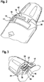
- an inventive power tool 10 is shown in the form of a battery-powered drill.
- the power tool 10 has, in a manner known per se, a drive motor 11, which acts on a drive spindle 13 via a gear 12.
- the transmission 12 of the power tool 10 at least two gear stages (not shown), of which the first gear stage, which has a higher reduction than the second gear stage, used for screwing, while the second gear stage is suitable for drilling. It is also essential that the maximum torque to be transmitted of the drive motor 11 to the drive spindle 13 can be set for the screwing function.
- actuating element 15 is in this case realized in the illustrated embodiment as a trained as a rotary ring 16 slide switch.
- the actuating element 15 could be formed instead of a rotary ring 16 as a rotary switch.
- the rotary ring 16 is adjustable in the housing of the drill 1 within a certain rotation angle range.
- the respective position of the operating element 17 or of the rotary ring 16 is displayed via a visual display 18.
- the optical display 18 comprises two separate display panels 19, 20, in which in particular a plurality of LEDs are arranged. It is essential here that in the one display field 19, the actuating element 15 is in the addressed first operating mode, in which the drill driver 1 allows a screwing, while the second display panel 20 is used to display the drilling operation.
- the arrangement of the display panels 19, 20 is such that the respective luminous LEDs are correlated or aligned with the position of the control element 17.
- the rotary ring 16 on its one end face on an electrically acting contact element 22 which is received positively on the rotary ring 16 in a preferably molded recess.
- the contact element 22 is part of a potentiometer 25 which is formed on an arcuate circuit board 26.
- the circuit board 26 is in turn connected to a circuit carrier 27, are arranged on the evaluation means 28 which are adapted to detect the position of the contact element 22 relative to the circuit board 26.
- the circuit board 26 has two conductor tracks 29, 30, which are arranged at a distance from one another and are electrically bridged by means of the contact element 22.
- the position or position of the contact element 22, and thus the rotational angular position of the rotary ring 16 is detected by the fact that according to the position of the rotary ring 16, the contact element 22 also occupies a position of the rotary ring 16 associated unique position.
- the contact element 22 bridges the two interconnects 29, 30 on the circuit board 26, so that the potentiometer 25 generates a very specific resistance, which is detected by means of the evaluation means 28.
- This detected value of the angular position of the rotary ring 16 is supplied by the evaluation means 28 to a control device of the power tool 10, not shown in the figures as an input value, which due to the position of the rotary ring 16, and possibly other additional input variables, the maximum torque to be transmitted Drive motor 1 by limiting the current of the drive motor 11 sets.
- locking cams 31 are formed on the rotary ring 16, which cooperate with a corresponding rotation of the rotary ring 16 with corresponding counter means, for example, in the housing and the operator on the one hand produce a tactile snapping when turning the rotary ring 16 and on the other a corresponding noise, which can be perceived by the operator.
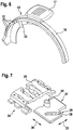
- an adjusting element in the form of an adjusting pin 33 is integrally formed on the rotary ring 16, an adjusting element in the form of an adjusting pin 33 is integrally formed.
- the adjusting pin 33 is part of a Gangvor lightsschalters 34, corresponding to the Fig. 7 to 9
- a stationary in the power tool 10 arranged guide housing 35 comprises, in which a corresponding to the double arrow 36 perpendicular to the direction of rotation of the rotary ring 16, whose direction of rotation is indicated by the double arrow 32, slidably disposed transmission plate 37 is arranged.
- a guide groove 38 is formed for the adjustment pin 33, which is formed open at its one end 39.
- the transfer plate 37 has on its upper side on a locking cam 40 which cooperates with two, integrally formed on the guide housing 35 latching clips 44, 45.
- the locking cam 40 takes two according to the position in the transfer plate 37, in the 8 and 9 shown positions in which the transmission plate 37 by means of a transmission lever 37 coupled to the shift lever 41, the transmission 12 of the power tool 10 either in the first gear, which is intended for screwing, or in the second gear, which is suitable for drilling adjusts.
- the adjustment between the two positions that is, the respective overcoming the latching clip 44, 45 by the locking cam 40, the operator both haptically and acoustically perceptible.
- the operation of the Gangvoriansschalters 34 is as follows: in the position of the rotary ring 16, in which the contact element 22 is in the region of the tracks 29, 30 of the potentiometer 25, which is synonymous with a first adjustment range 42 (FIGS. Fig. 2 ) of the rotary ring 16 for the screwing mode, the adjusting pin 33 is disengaged from the guide groove 38 of the transmission plate 37. That is, the shift lever 41 assumes a position in which the transmission 12 of the power tool 10 is in first gear. Upon rotation of the rotary ring 16 over the range of the potentiometer 25, which is synonymous with a second adjustment 43, the adjustment pin 33 comes into engagement with the guide groove 38 of the transfer plate 37.
Landscapes
- Engineering & Computer Science (AREA)
- Mechanical Engineering (AREA)
- Drilling And Boring (AREA)
- Details Of Spanners, Wrenches, And Screw Drivers And Accessories (AREA)
- Portable Power Tools In General (AREA)
Claims (6)
- Outil électrique (10), en particulier visseuse (1), avec un moteur d'entraînement (11), qui est couplé à un élément de sortie (13), en particulier à une broche d'entraînement par une transmission (12) présentant plusieurs rapports de transmission, dans lequel le couple produit par le moteur d'entraînement (11) est réglable au moyen d'un premier dispositif de réglage actionnable manuellement (25), et avec un deuxième dispositif de réglage actionnable manuellement (34), en particulier pour le réglage du rapport de transmission de la transmission (12), dans lequel les deux dispositifs de réglage (25, 34) peuvent être actionnés par un dispositif d'actionnement commun (15),
dans lequel l'élément d'actionnement (15) est constitué par un élément d'actionnement mécanique (15) sous la forme d'un interrupteur glissant (16) ou rotatif, et dans lequel l'élément d'actionnement (15) présente une première zone de réglage (42), dans laquelle l'élément d'actionnement (15) coopère exclusivement avec le premier dispositif de réglage (25), et avec une deuxième zone de réglage (43) se raccordant à la première zone de réglage (42), dans laquelle l'élément d'actionnement (15) coopère (34) exclusivement avec le deuxième dispositif de réglage,
dans lequel un élément de réglage (33) est disposé sur l'élément d'actionnement (15) et coopère dans la deuxième zone de réglage (43) de l'élément d'actionnement (15) avec un élément de réglage de rapport (37),
caractérisé en ce que l'élément de réglage coopère avec un interrupteur de présélection de rapport (34) et est formé par un ergot de réglage (33), en ce que l'élément de réglage de rapport est formé par un interrupteur glissant (37), et en ce que l'interrupteur glissant (37) présente une découpe sous la forme d'une rainure de guidage (38), avec laquelle l'ergot de réglage (33) vient en liaison active au commencement de la deuxième zone de réglage (43) de l'élément d'actionnement (15). - Outil électrique selon la revendication 1,
caractérisé en ce que le premier dispositif de réglage destiné au réglage du couple comprend un potentiomètre (25) pour détecter la position de l'élément d'actionnement (15), et dont la valeur de la résistance peut être modifiée au moyen d'un élément de contact (22) disposé sur l'élément d'actionnement (15) et agissant comme pontage entre des pistes conductrices (29, 30). - Outil électrique selon la revendication 2,
caractérisé en ce que le potentiomètre (25) est disposé sur un support d'interrupteur (27), en ce que le support d'interrupteur (27) présente des moyens d'évaluation (28) pour la détection de la position de l'élément d'actionnement (15) sur la base de la valeur de la résistance du potentiomètre (25) et en ce que le support d'interrupteur (27) est relié à un dispositif de commande pour la commande du moteur d'entraînement (11) en ce qui concerne son couple transmissible. - Outil électrique selon la revendication 1,
caractérisé en ce que l'interrupteur glissant (37) est couplé à un levier de commutation (41), qui dans une position déterminée de l'ergot de réglage (33) dans la rainure de guidage (38) commute la transmission (12) d'un premier rapport à un deuxième rapport. - Outil électrique selon l'une quelconque des revendications 1 à 4, caractérisé en ce que la position de l'élément d'actionnement (15) est représentée au moyen d'un affichage optique (18).
- Outil électrique selon la revendication 5,
caractérisé en ce que l'affichage optique (18) est disposé dans la région de la course de réglage d'un élément de commande (17) de l'élément d'actionnement (15) .
Priority Applications (1)
| Application Number | Priority Date | Filing Date | Title |
|---|---|---|---|
| EP18197884.2A EP3581332B1 (fr) | 2010-05-25 | 2011-04-15 | Outil électrique, en particulier perceuse-visseuse |
Applications Claiming Priority (2)
| Application Number | Priority Date | Filing Date | Title |
|---|---|---|---|
| DE102010029267A DE102010029267A1 (de) | 2010-05-25 | 2010-05-25 | Elektrowerkzeug, insbesondere Bohrschrauber |
| PCT/EP2011/056029 WO2011147641A1 (fr) | 2010-05-25 | 2011-04-15 | Outil électrique, en particulier visseuse |
Related Child Applications (2)
| Application Number | Title | Priority Date | Filing Date |
|---|---|---|---|
| EP18197884.2A Division EP3581332B1 (fr) | 2010-05-25 | 2011-04-15 | Outil électrique, en particulier perceuse-visseuse |
| EP18197884.2A Division-Into EP3581332B1 (fr) | 2010-05-25 | 2011-04-15 | Outil électrique, en particulier perceuse-visseuse |
Publications (2)
| Publication Number | Publication Date |
|---|---|
| EP2576144A1 EP2576144A1 (fr) | 2013-04-10 |
| EP2576144B1 true EP2576144B1 (fr) | 2018-12-12 |
Family
ID=44148914
Family Applications (2)
| Application Number | Title | Priority Date | Filing Date |
|---|---|---|---|
| EP11715503.6A Not-in-force EP2576144B1 (fr) | 2010-05-25 | 2011-04-15 | Outil électrique, en particulier visseuse |
| EP18197884.2A Active EP3581332B1 (fr) | 2010-05-25 | 2011-04-15 | Outil électrique, en particulier perceuse-visseuse |
Family Applications After (1)
| Application Number | Title | Priority Date | Filing Date |
|---|---|---|---|
| EP18197884.2A Active EP3581332B1 (fr) | 2010-05-25 | 2011-04-15 | Outil électrique, en particulier perceuse-visseuse |
Country Status (5)
| Country | Link |
|---|---|
| US (1) | US9687977B2 (fr) |
| EP (2) | EP2576144B1 (fr) |
| CN (2) | CN102892555B (fr) |
| DE (1) | DE102010029267A1 (fr) |
| WO (1) | WO2011147641A1 (fr) |
Families Citing this family (21)
| Publication number | Priority date | Publication date | Assignee | Title |
|---|---|---|---|---|
| EP1857228B1 (fr) * | 2006-05-19 | 2008-07-09 | Black & Decker, Inc. | Mécanisme de changement de mode pour un outil motorisé |
| DE202013012792U1 (de) * | 2013-02-11 | 2019-08-28 | Robert Bosch Gmbh | Handwerkzeugmaschine |
| CN104227669B (zh) * | 2013-06-20 | 2016-04-06 | 苏州宝时得电动工具有限公司 | 手持电动工具 |
| DE102013222550B4 (de) | 2013-11-06 | 2024-12-19 | Robert Bosch Gmbh | Handwerkzeugmaschine |
| WO2016196918A1 (fr) | 2015-06-05 | 2016-12-08 | Ingersoll-Rand Company | Interfaces utilisateur d'outil électrique |
| WO2016196984A1 (fr) | 2015-06-05 | 2016-12-08 | Ingersoll-Rand Company | Machines portatives à moteur à modes de fonctionnement sélectionnables par l'utilisateur |
| WO2016196891A1 (fr) * | 2015-06-05 | 2016-12-08 | Ingersoll-Rand Company | Interfaces utilisateur de machine-outil électrique |
| US11260517B2 (en) | 2015-06-05 | 2022-03-01 | Ingersoll-Rand Industrial U.S., Inc. | Power tool housings |
| US10668614B2 (en) | 2015-06-05 | 2020-06-02 | Ingersoll-Rand Industrial U.S., Inc. | Impact tools with ring gear alignment features |
| DE102015214315A1 (de) * | 2015-07-29 | 2017-02-02 | Robert Bosch Gmbh | Tragbare Werkzeugmaschine |
| DE102015119987B4 (de) * | 2015-11-18 | 2024-01-25 | C. & E. Fein Gmbh | Handwerkzeugmaschine mit schaltbarem Getriebe |
| DE102015226188A1 (de) * | 2015-12-21 | 2017-06-22 | Robert Bosch Gmbh | Verfahren zu einer Sicherung einer Benutzung zumindest einer Handwerkzeugmaschine |
| US10744632B2 (en) * | 2017-11-29 | 2020-08-18 | Nanjing Chervon Industry Co., Ltd. | Power tool |
| DE102017222006A1 (de) | 2017-12-06 | 2019-06-06 | Robert Bosch Gmbh | Handwerkzeugmaschine mit einer Moduseinstelleinrichtung |
| DE102018206866A1 (de) * | 2018-05-04 | 2019-11-07 | Robert Bosch Gmbh | Werkzeugmaschinenvorrichtung |
| CN110617325B (zh) * | 2018-06-20 | 2021-06-11 | 宝时得科技(中国)有限公司 | 变速传动机构及其变速工具 |
| DE102018214092A1 (de) * | 2018-08-21 | 2020-02-27 | Robert Bosch Gmbh | Umschaltvorrichtung für einen Bohrhammer und Bohrhammer mit einer Umschaltvorrichtung |
| WO2021173602A1 (fr) * | 2020-02-24 | 2021-09-02 | Milwaukee Electric Tool Corporation | Outil à percussion |
| US11602833B2 (en) | 2020-06-02 | 2023-03-14 | Snap-On Incorporated | Direction selector mechanism for a power tool |
| US11412631B2 (en) * | 2020-08-26 | 2022-08-09 | Snap-On Incorporated | PCB with integrated switches |
| DE102023200535A1 (de) * | 2023-01-24 | 2024-07-25 | Robert Bosch Gesellschaft mit beschränkter Haftung | Handwerkzeugmaschine |
Family Cites Families (38)
| Publication number | Priority date | Publication date | Assignee | Title |
|---|---|---|---|---|
| US3646375A (en) * | 1970-12-30 | 1972-02-29 | Dale Electronics | Motorized potentiometer with overload clutch and interchangeable gear ratio |
| FR2517999B1 (fr) * | 1981-12-15 | 1985-06-21 | Peugeot Outillage Elect | Perceuse portative a plusieurs vitesses |
| JPH0639899Y2 (ja) * | 1986-08-08 | 1994-10-19 | 株式会社マキタ | 回転電動工具におけるトルク調整装置 |
| US5014793A (en) * | 1989-04-10 | 1991-05-14 | Measurement Specialties, Inc. | Variable speed DC motor controller apparatus particularly adapted for control of portable-power tools |
| DE4305967C2 (de) | 1993-02-26 | 1997-03-06 | Kress Elektrik Gmbh & Co | Schaltvorrichtung zur Spindelarretierung für Elektrowerkzeuge |
| US5451127A (en) * | 1994-04-12 | 1995-09-19 | Chung; Lee-Hsin-Chih | Dual-function electrical hand drill |
| DE19501430A1 (de) * | 1995-01-19 | 1996-07-25 | Marquardt Gmbh | Ansteuerung für einen Elektromotor |
| ES2148962T3 (es) * | 1996-03-15 | 2000-10-16 | Marquardt Gmbh | Conmutador electrico. |
| GB2327054A (en) | 1997-07-08 | 1999-01-13 | Black & Decker Inc | Shaft locking |
| CA2293857A1 (fr) * | 2000-01-04 | 2001-07-04 | Hui Li | Capteur pouvant deceler la position angulaire absolue d'un objet cylindrique |
| DE10023174A1 (de) * | 2000-05-11 | 2001-11-22 | Bosch Gmbh Robert | Werkzeugmaschine, insbesondere Handwerkzeugmaschine |
| US6502648B2 (en) * | 2001-01-23 | 2003-01-07 | Black & Decker Inc. | 360 degree clutch collar |
| DE10212721A1 (de) * | 2001-03-24 | 2002-09-26 | Marquardt Gmbh | Ansteuereinrichtung für einen Elektromotor |
| US20030089511A1 (en) * | 2001-11-12 | 2003-05-15 | Yukio Tsuneda | Electric tool |
| US6912790B2 (en) | 2001-12-03 | 2005-07-05 | Milwaukee Electric Tool Corporation | Handle arrangement for a reciprocating saw |
| CN2545688Y (zh) | 2002-05-17 | 2003-04-16 | 沈新权 | 电动工具开关 |
| DE10240361A1 (de) * | 2002-09-02 | 2004-03-11 | Hilti Ag | Drehende und schlagende Elektrohandwerkzeugmaschine |
| DE10325922A1 (de) * | 2003-06-07 | 2005-01-05 | Hilti Ag | Geräteschalter für elektrische Handwerkzeuge |
| DE10337260A1 (de) | 2003-08-18 | 2005-03-10 | Bosch Gmbh Robert | Bedienungsmodul für eine Elektrowerkzeugmaschine |
| DE102004018084B3 (de) * | 2004-04-08 | 2005-11-17 | Hilti Ag | Hammerbohrgerät |
| JP4400303B2 (ja) * | 2004-05-12 | 2010-01-20 | パナソニック電工株式会社 | インパクト回転工具 |
| DE102004051911A1 (de) | 2004-10-26 | 2006-04-27 | Robert Bosch Gmbh | Handwerkzeugmaschine, insbesondere Bohrschrauber |
| DE102004057686A1 (de) * | 2004-11-30 | 2006-06-01 | Robert Bosch Gmbh | Schaltvorrichtung |
| ATE476272T1 (de) * | 2005-08-29 | 2010-08-15 | Demain Technology Pty Ltd | Kraftbetriebenes werkzeug |
| CN101253015A (zh) * | 2005-08-29 | 2008-08-27 | 迪美科技控股有限公司 | 动力工具 |
| DE602006013863D1 (de) | 2005-11-04 | 2010-06-02 | Bosch Gmbh Robert | Verfahren und vorrichtung für einen gelenkbohrer |
| EP1857228B1 (fr) * | 2006-05-19 | 2008-07-09 | Black & Decker, Inc. | Mécanisme de changement de mode pour un outil motorisé |
| CN101091998B (zh) * | 2006-06-19 | 2012-03-28 | 苏州宝时得电动工具有限公司 | 变速工具 |
| US8303449B2 (en) * | 2006-08-01 | 2012-11-06 | Techtronic Power Tools Technology Limited | Automatic transmission for a power tool |
| US7759898B2 (en) * | 2006-11-28 | 2010-07-20 | Black & Decker Inc. | Battery pack lockout arrangement for cordless power tools |
| EP2030709A3 (fr) * | 2007-08-29 | 2013-01-16 | Positec Power Tools (Suzhou) Co., Ltd. | Outil électrique |
| US7717192B2 (en) * | 2007-11-21 | 2010-05-18 | Black & Decker Inc. | Multi-mode drill with mode collar |
| GB0801302D0 (en) * | 2008-01-24 | 2008-03-05 | Black & Decker Inc | Handle assembly for power tool |
| DE102008000176A1 (de) * | 2008-01-30 | 2009-08-06 | Robert Bosch Gmbh | Elektrowerkzeug |
| DE102008040096A1 (de) | 2008-07-02 | 2010-01-07 | Robert Bosch Gmbh | Verfahren zum Betreiben einer Elektrowerkzeugmaschine und eine Antriebseinheit für eine Elektrowerkzeugmaschine |
| US9193053B2 (en) * | 2008-09-25 | 2015-11-24 | Black & Decker Inc. | Hybrid impact tool |
| DE102009001132B4 (de) * | 2009-02-25 | 2022-04-28 | Robert Bosch Gmbh | Elektrowerkzeug |
| DE102010001967A1 (de) * | 2010-02-16 | 2011-08-18 | Robert Bosch GmbH, 70469 | Bedienelement für Handwerkzeugmaschine |
-
2010
- 2010-05-25 DE DE102010029267A patent/DE102010029267A1/de not_active Withdrawn
-
2011
- 2011-04-15 CN CN201180025692.XA patent/CN102892555B/zh active Active
- 2011-04-15 EP EP11715503.6A patent/EP2576144B1/fr not_active Not-in-force
- 2011-04-15 CN CN201510763990.9A patent/CN105345751B/zh active Active
- 2011-04-15 US US13/696,341 patent/US9687977B2/en active Active
- 2011-04-15 WO PCT/EP2011/056029 patent/WO2011147641A1/fr not_active Ceased
- 2011-04-15 EP EP18197884.2A patent/EP3581332B1/fr active Active
Non-Patent Citations (1)
| Title |
|---|
| None * |
Also Published As
| Publication number | Publication date |
|---|---|
| DE102010029267A1 (de) | 2011-12-01 |
| US9687977B2 (en) | 2017-06-27 |
| EP3581332B1 (fr) | 2023-03-01 |
| EP2576144A1 (fr) | 2013-04-10 |
| CN105345751A (zh) | 2016-02-24 |
| WO2011147641A1 (fr) | 2011-12-01 |
| CN102892555A (zh) | 2013-01-23 |
| CN105345751B (zh) | 2018-06-19 |
| CN102892555B (zh) | 2016-03-30 |
| EP3581332A1 (fr) | 2019-12-18 |
| US20130206435A1 (en) | 2013-08-15 |
Similar Documents
| Publication | Publication Date | Title |
|---|---|---|
| EP2576144B1 (fr) | Outil électrique, en particulier visseuse | |
| EP2457002B1 (fr) | Dispositif de detection de la position d'un levier de changement et/ou de selection de vitesses pour une boite de vitesses et dispositif de commande pour la boite de vitesses d'un vehicule automobile | |
| DE102010007913B4 (de) | Drehsteller | |
| WO2008011946A1 (fr) | Dispositif de changement de vitesses pour une boîte de vitesses automatisée ou automatique | |
| DE102010009338A1 (de) | Getriebesteller | |
| EP2329508B1 (fr) | Commande manuelle | |
| DE102006007600B4 (de) | Drehsteller für elektrische oder elektronische Gräte in einem Kraftfahrzeug | |
| DE102007039318B4 (de) | Drehschalter mit haptischer Markierung | |
| EP2122206B1 (fr) | Dispositif de changement de vitesse pour une boîte de vitesses d'un véhicule | |
| EP2143980A2 (fr) | Agencement destiné à sélectionner et à commuter des vitesses dans une boîte de vitesses d'un véhicule | |
| DE202017102057U1 (de) | Zwischen unterschiedlichen Betriebsarten umschaltbarer Multifunktions-Elektrohammer | |
| EP3099959B1 (fr) | Dispositif de démultiplication et procédé de démultiplication d'un angle d'actionnement d'un levier de vitesses pour un actionnement de changement de vitesse d'une boîte de vitesses de véhicule | |
| DE102014102982B3 (de) | Lenkwinkelsensor | |
| EP2799170A1 (fr) | Machine-outil à main et procédé de commande | |
| DE60121299T2 (de) | Lenkeinrichtung mit variablem Winkelverhältnis | |
| EP2025975B1 (fr) | Dispositif sélecteur de vitesse destiné à sélectionner et à commuter une vitesse pour une boîte de vitesses manuelle d'un véhicule | |
| EP1870617A2 (fr) | Dispositif d'actionnement pour un engrenage d'un véhicule | |
| EP2023020B1 (fr) | Engrenage doté d'une assistance à la commutation et d'une protection en cas de panne | |
| DE102007019470A1 (de) | Schalteinheit für ein insbesondere elektronisch geschaltetes Getriebe eines Kraftfahrzeugs | |
| DE102010048601B4 (de) | Eingabevorrichtung mit variablem Betätigungsgefühl | |
| DE102008060114A1 (de) | Multifunktions-Bedienelement | |
| DE102007030303A1 (de) | Multifunktions-Bedienelement für ein Kraftfahrzeug | |
| DE102007002691A1 (de) | Aktuator zum Verschwenken einer Scheinwerferkomponente | |
| WO2015149798A1 (fr) | Système d'actionnement de commutateur à cames dans une réalisation augmentant la dynamique par une élévation de la tension | |
| DE102012213177B4 (de) | Schaltdom für ein Schaltgetriebe eines Kraftfahrzeugs |
Legal Events
| Date | Code | Title | Description |
|---|---|---|---|
| PUAI | Public reference made under article 153(3) epc to a published international application that has entered the european phase |
Free format text: ORIGINAL CODE: 0009012 |
|
| 17P | Request for examination filed |
Effective date: 20130102 |
|
| AK | Designated contracting states |
Kind code of ref document: A1 Designated state(s): AL AT BE BG CH CY CZ DE DK EE ES FI FR GB GR HR HU IE IS IT LI LT LU LV MC MK MT NL NO PL PT RO RS SE SI SK SM TR |
|
| DAX | Request for extension of the european patent (deleted) | ||
| REG | Reference to a national code |
Ref country code: DE Ref legal event code: R079 Ref document number: 502011015147 Country of ref document: DE Free format text: PREVIOUS MAIN CLASS: B25B0021000000 Ipc: B25F0005000000 |
|
| GRAP | Despatch of communication of intention to grant a patent |
Free format text: ORIGINAL CODE: EPIDOSNIGR1 |
|
| STAA | Information on the status of an ep patent application or granted ep patent |
Free format text: STATUS: GRANT OF PATENT IS INTENDED |
|
| RIC1 | Information provided on ipc code assigned before grant |
Ipc: B25F 5/00 20060101AFI20180614BHEP |
|
| INTG | Intention to grant announced |
Effective date: 20180705 |
|
| GRAS | Grant fee paid |
Free format text: ORIGINAL CODE: EPIDOSNIGR3 |
|
| GRAA | (expected) grant |
Free format text: ORIGINAL CODE: 0009210 |
|
| STAA | Information on the status of an ep patent application or granted ep patent |
Free format text: STATUS: THE PATENT HAS BEEN GRANTED |
|
| AK | Designated contracting states |
Kind code of ref document: B1 Designated state(s): AL AT BE BG CH CY CZ DE DK EE ES FI FR GB GR HR HU IE IS IT LI LT LU LV MC MK MT NL NO PL PT RO RS SE SI SK SM TR |
|
| REG | Reference to a national code |
Ref country code: GB Ref legal event code: FG4D Free format text: NOT ENGLISH |
|
| REG | Reference to a national code |
Ref country code: CH Ref legal event code: EP |
|
| REG | Reference to a national code |
Ref country code: AT Ref legal event code: REF Ref document number: 1075325 Country of ref document: AT Kind code of ref document: T Effective date: 20181215 |
|
| REG | Reference to a national code |
Ref country code: DE Ref legal event code: R096 Ref document number: 502011015147 Country of ref document: DE |
|
| REG | Reference to a national code |
Ref country code: IE Ref legal event code: FG4D Free format text: LANGUAGE OF EP DOCUMENT: GERMAN |
|
| REG | Reference to a national code |
Ref country code: NL Ref legal event code: MP Effective date: 20181212 |
|
| REG | Reference to a national code |
Ref country code: LT Ref legal event code: MG4D |
|
| PG25 | Lapsed in a contracting state [announced via postgrant information from national office to epo] |
Ref country code: ES Free format text: LAPSE BECAUSE OF FAILURE TO SUBMIT A TRANSLATION OF THE DESCRIPTION OR TO PAY THE FEE WITHIN THE PRESCRIBED TIME-LIMIT Effective date: 20181212 Ref country code: LV Free format text: LAPSE BECAUSE OF FAILURE TO SUBMIT A TRANSLATION OF THE DESCRIPTION OR TO PAY THE FEE WITHIN THE PRESCRIBED TIME-LIMIT Effective date: 20181212 Ref country code: FI Free format text: LAPSE BECAUSE OF FAILURE TO SUBMIT A TRANSLATION OF THE DESCRIPTION OR TO PAY THE FEE WITHIN THE PRESCRIBED TIME-LIMIT Effective date: 20181212 Ref country code: LT Free format text: LAPSE BECAUSE OF FAILURE TO SUBMIT A TRANSLATION OF THE DESCRIPTION OR TO PAY THE FEE WITHIN THE PRESCRIBED TIME-LIMIT Effective date: 20181212 Ref country code: HR Free format text: LAPSE BECAUSE OF FAILURE TO SUBMIT A TRANSLATION OF THE DESCRIPTION OR TO PAY THE FEE WITHIN THE PRESCRIBED TIME-LIMIT Effective date: 20181212 Ref country code: BG Free format text: LAPSE BECAUSE OF FAILURE TO SUBMIT A TRANSLATION OF THE DESCRIPTION OR TO PAY THE FEE WITHIN THE PRESCRIBED TIME-LIMIT Effective date: 20190312 Ref country code: NO Free format text: LAPSE BECAUSE OF FAILURE TO SUBMIT A TRANSLATION OF THE DESCRIPTION OR TO PAY THE FEE WITHIN THE PRESCRIBED TIME-LIMIT Effective date: 20190312 |
|
| PG25 | Lapsed in a contracting state [announced via postgrant information from national office to epo] |
Ref country code: RS Free format text: LAPSE BECAUSE OF FAILURE TO SUBMIT A TRANSLATION OF THE DESCRIPTION OR TO PAY THE FEE WITHIN THE PRESCRIBED TIME-LIMIT Effective date: 20181212 Ref country code: GR Free format text: LAPSE BECAUSE OF FAILURE TO SUBMIT A TRANSLATION OF THE DESCRIPTION OR TO PAY THE FEE WITHIN THE PRESCRIBED TIME-LIMIT Effective date: 20190313 Ref country code: AL Free format text: LAPSE BECAUSE OF FAILURE TO SUBMIT A TRANSLATION OF THE DESCRIPTION OR TO PAY THE FEE WITHIN THE PRESCRIBED TIME-LIMIT Effective date: 20181212 Ref country code: SE Free format text: LAPSE BECAUSE OF FAILURE TO SUBMIT A TRANSLATION OF THE DESCRIPTION OR TO PAY THE FEE WITHIN THE PRESCRIBED TIME-LIMIT Effective date: 20181212 |
|
| PG25 | Lapsed in a contracting state [announced via postgrant information from national office to epo] |
Ref country code: NL Free format text: LAPSE BECAUSE OF FAILURE TO SUBMIT A TRANSLATION OF THE DESCRIPTION OR TO PAY THE FEE WITHIN THE PRESCRIBED TIME-LIMIT Effective date: 20181212 |
|
| PG25 | Lapsed in a contracting state [announced via postgrant information from national office to epo] |
Ref country code: CZ Free format text: LAPSE BECAUSE OF FAILURE TO SUBMIT A TRANSLATION OF THE DESCRIPTION OR TO PAY THE FEE WITHIN THE PRESCRIBED TIME-LIMIT Effective date: 20181212 Ref country code: PT Free format text: LAPSE BECAUSE OF FAILURE TO SUBMIT A TRANSLATION OF THE DESCRIPTION OR TO PAY THE FEE WITHIN THE PRESCRIBED TIME-LIMIT Effective date: 20190412 Ref country code: PL Free format text: LAPSE BECAUSE OF FAILURE TO SUBMIT A TRANSLATION OF THE DESCRIPTION OR TO PAY THE FEE WITHIN THE PRESCRIBED TIME-LIMIT Effective date: 20181212 Ref country code: IT Free format text: LAPSE BECAUSE OF FAILURE TO SUBMIT A TRANSLATION OF THE DESCRIPTION OR TO PAY THE FEE WITHIN THE PRESCRIBED TIME-LIMIT Effective date: 20181212 |
|
| PG25 | Lapsed in a contracting state [announced via postgrant information from national office to epo] |
Ref country code: IS Free format text: LAPSE BECAUSE OF FAILURE TO SUBMIT A TRANSLATION OF THE DESCRIPTION OR TO PAY THE FEE WITHIN THE PRESCRIBED TIME-LIMIT Effective date: 20190412 Ref country code: SK Free format text: LAPSE BECAUSE OF FAILURE TO SUBMIT A TRANSLATION OF THE DESCRIPTION OR TO PAY THE FEE WITHIN THE PRESCRIBED TIME-LIMIT Effective date: 20181212 Ref country code: SM Free format text: LAPSE BECAUSE OF FAILURE TO SUBMIT A TRANSLATION OF THE DESCRIPTION OR TO PAY THE FEE WITHIN THE PRESCRIBED TIME-LIMIT Effective date: 20181212 Ref country code: EE Free format text: LAPSE BECAUSE OF FAILURE TO SUBMIT A TRANSLATION OF THE DESCRIPTION OR TO PAY THE FEE WITHIN THE PRESCRIBED TIME-LIMIT Effective date: 20181212 Ref country code: RO Free format text: LAPSE BECAUSE OF FAILURE TO SUBMIT A TRANSLATION OF THE DESCRIPTION OR TO PAY THE FEE WITHIN THE PRESCRIBED TIME-LIMIT Effective date: 20181212 |
|
| REG | Reference to a national code |
Ref country code: DE Ref legal event code: R097 Ref document number: 502011015147 Country of ref document: DE |
|
| PLBE | No opposition filed within time limit |
Free format text: ORIGINAL CODE: 0009261 |
|
| STAA | Information on the status of an ep patent application or granted ep patent |
Free format text: STATUS: NO OPPOSITION FILED WITHIN TIME LIMIT |
|
| PG25 | Lapsed in a contracting state [announced via postgrant information from national office to epo] |
Ref country code: SI Free format text: LAPSE BECAUSE OF FAILURE TO SUBMIT A TRANSLATION OF THE DESCRIPTION OR TO PAY THE FEE WITHIN THE PRESCRIBED TIME-LIMIT Effective date: 20181212 Ref country code: DK Free format text: LAPSE BECAUSE OF FAILURE TO SUBMIT A TRANSLATION OF THE DESCRIPTION OR TO PAY THE FEE WITHIN THE PRESCRIBED TIME-LIMIT Effective date: 20181212 |
|
| 26N | No opposition filed |
Effective date: 20190913 |
|
| REG | Reference to a national code |
Ref country code: CH Ref legal event code: PL |
|
| REG | Reference to a national code |
Ref country code: BE Ref legal event code: MM Effective date: 20190430 |
|
| PG25 | Lapsed in a contracting state [announced via postgrant information from national office to epo] |
Ref country code: MC Free format text: LAPSE BECAUSE OF FAILURE TO SUBMIT A TRANSLATION OF THE DESCRIPTION OR TO PAY THE FEE WITHIN THE PRESCRIBED TIME-LIMIT Effective date: 20181212 Ref country code: LU Free format text: LAPSE BECAUSE OF NON-PAYMENT OF DUE FEES Effective date: 20190415 |
|
| PG25 | Lapsed in a contracting state [announced via postgrant information from national office to epo] |
Ref country code: CH Free format text: LAPSE BECAUSE OF NON-PAYMENT OF DUE FEES Effective date: 20190430 Ref country code: LI Free format text: LAPSE BECAUSE OF NON-PAYMENT OF DUE FEES Effective date: 20190430 |
|
| PG25 | Lapsed in a contracting state [announced via postgrant information from national office to epo] |
Ref country code: BE Free format text: LAPSE BECAUSE OF NON-PAYMENT OF DUE FEES Effective date: 20190430 Ref country code: FR Free format text: LAPSE BECAUSE OF NON-PAYMENT OF DUE FEES Effective date: 20190430 |
|
| PG25 | Lapsed in a contracting state [announced via postgrant information from national office to epo] |
Ref country code: TR Free format text: LAPSE BECAUSE OF FAILURE TO SUBMIT A TRANSLATION OF THE DESCRIPTION OR TO PAY THE FEE WITHIN THE PRESCRIBED TIME-LIMIT Effective date: 20181212 |
|
| PG25 | Lapsed in a contracting state [announced via postgrant information from national office to epo] |
Ref country code: IE Free format text: LAPSE BECAUSE OF NON-PAYMENT OF DUE FEES Effective date: 20190415 |
|
| REG | Reference to a national code |
Ref country code: AT Ref legal event code: MM01 Ref document number: 1075325 Country of ref document: AT Kind code of ref document: T Effective date: 20190415 |
|
| PG25 | Lapsed in a contracting state [announced via postgrant information from national office to epo] |
Ref country code: AT Free format text: LAPSE BECAUSE OF NON-PAYMENT OF DUE FEES Effective date: 20190415 |
|
| PG25 | Lapsed in a contracting state [announced via postgrant information from national office to epo] |
Ref country code: CY Free format text: LAPSE BECAUSE OF FAILURE TO SUBMIT A TRANSLATION OF THE DESCRIPTION OR TO PAY THE FEE WITHIN THE PRESCRIBED TIME-LIMIT Effective date: 20181212 |
|
| PG25 | Lapsed in a contracting state [announced via postgrant information from national office to epo] |
Ref country code: HU Free format text: LAPSE BECAUSE OF FAILURE TO SUBMIT A TRANSLATION OF THE DESCRIPTION OR TO PAY THE FEE WITHIN THE PRESCRIBED TIME-LIMIT; INVALID AB INITIO Effective date: 20110415 Ref country code: MT Free format text: LAPSE BECAUSE OF FAILURE TO SUBMIT A TRANSLATION OF THE DESCRIPTION OR TO PAY THE FEE WITHIN THE PRESCRIBED TIME-LIMIT Effective date: 20181212 |
|
| PG25 | Lapsed in a contracting state [announced via postgrant information from national office to epo] |
Ref country code: MK Free format text: LAPSE BECAUSE OF FAILURE TO SUBMIT A TRANSLATION OF THE DESCRIPTION OR TO PAY THE FEE WITHIN THE PRESCRIBED TIME-LIMIT Effective date: 20181212 |
|
| PGFP | Annual fee paid to national office [announced via postgrant information from national office to epo] |
Ref country code: GB Payment date: 20240423 Year of fee payment: 14 |
|
| PGFP | Annual fee paid to national office [announced via postgrant information from national office to epo] |
Ref country code: DE Payment date: 20240619 Year of fee payment: 14 |
|
| REG | Reference to a national code |
Ref country code: DE Ref legal event code: R119 Ref document number: 502011015147 Country of ref document: DE |
|
| GBPC | Gb: european patent ceased through non-payment of renewal fee |
Effective date: 20250415 |
|
| PG25 | Lapsed in a contracting state [announced via postgrant information from national office to epo] |
Ref country code: DE Free format text: LAPSE BECAUSE OF NON-PAYMENT OF DUE FEES Effective date: 20251104 |
|
| PG25 | Lapsed in a contracting state [announced via postgrant information from national office to epo] |
Ref country code: GB Free format text: LAPSE BECAUSE OF NON-PAYMENT OF DUE FEES Effective date: 20250415 |