EP2576182B1 - Procédé et dispositif de coupe de barre pour bouteille en matière plastique moulée par soufflage - Google Patents
Procédé et dispositif de coupe de barre pour bouteille en matière plastique moulée par soufflage Download PDFInfo
- Publication number
- EP2576182B1 EP2576182B1 EP11787114.5A EP11787114A EP2576182B1 EP 2576182 B1 EP2576182 B1 EP 2576182B1 EP 11787114 A EP11787114 A EP 11787114A EP 2576182 B1 EP2576182 B1 EP 2576182B1
- Authority
- EP
- European Patent Office
- Prior art keywords
- log
- blade
- support plate
- neck
- neck support
- Prior art date
- Legal status (The legal status is an assumption and is not a legal conclusion. Google has not performed a legal analysis and makes no representation as to the accuracy of the status listed.)
- Active
Links
Images




Classifications
-
- B—PERFORMING OPERATIONS; TRANSPORTING
- B29—WORKING OF PLASTICS; WORKING OF SUBSTANCES IN A PLASTIC STATE IN GENERAL
- B29C—SHAPING OR JOINING OF PLASTICS; SHAPING OF MATERIAL IN A PLASTIC STATE, NOT OTHERWISE PROVIDED FOR; AFTER-TREATMENT OF THE SHAPED PRODUCTS, e.g. REPAIRING
- B29C49/00—Blow-moulding, i.e. blowing a preform or parison to a desired shape within a mould; Apparatus therefor
- B29C49/42—Component parts, details or accessories; Auxiliary operations
- B29C49/72—Deflashing outside the mould
- B29C49/74—Deflashing the neck portion
-
- B—PERFORMING OPERATIONS; TRANSPORTING
- B29—WORKING OF PLASTICS; WORKING OF SUBSTANCES IN A PLASTIC STATE IN GENERAL
- B29C—SHAPING OR JOINING OF PLASTICS; SHAPING OF MATERIAL IN A PLASTIC STATE, NOT OTHERWISE PROVIDED FOR; AFTER-TREATMENT OF THE SHAPED PRODUCTS, e.g. REPAIRING
- B29C49/00—Blow-moulding, i.e. blowing a preform or parison to a desired shape within a mould; Apparatus therefor
- B29C49/42—Component parts, details or accessories; Auxiliary operations
- B29C49/48—Moulds
- B29C49/50—Moulds having cutting or deflashing means
-
- B—PERFORMING OPERATIONS; TRANSPORTING
- B29—WORKING OF PLASTICS; WORKING OF SUBSTANCES IN A PLASTIC STATE IN GENERAL
- B29C—SHAPING OR JOINING OF PLASTICS; SHAPING OF MATERIAL IN A PLASTIC STATE, NOT OTHERWISE PROVIDED FOR; AFTER-TREATMENT OF THE SHAPED PRODUCTS, e.g. REPAIRING
- B29C49/00—Blow-moulding, i.e. blowing a preform or parison to a desired shape within a mould; Apparatus therefor
- B29C49/42—Component parts, details or accessories; Auxiliary operations
- B29C49/76—Neck calibration
-
- B—PERFORMING OPERATIONS; TRANSPORTING
- B26—HAND CUTTING TOOLS; CUTTING; SEVERING
- B26D—CUTTING; DETAILS COMMON TO MACHINES FOR PERFORATING, PUNCHING, CUTTING-OUT, STAMPING-OUT OR SEVERING
- B26D7/00—Details of apparatus for cutting, cutting-out, stamping-out, punching, perforating, or severing by means other than cutting
- B26D7/26—Means for mounting or adjusting the cutting member; Means for adjusting the stroke of the cutting member
- B26D2007/2657—Auxiliary carriages for moving the tool holders
-
- B—PERFORMING OPERATIONS; TRANSPORTING
- B29—WORKING OF PLASTICS; WORKING OF SUBSTANCES IN A PLASTIC STATE IN GENERAL
- B29L—INDEXING SCHEME ASSOCIATED WITH SUBCLASS B29C, RELATING TO PARTICULAR ARTICLES
- B29L2031/00—Other particular articles
- B29L2031/712—Containers; Packaging elements or accessories, Packages
- B29L2031/7158—Bottles
-
- Y—GENERAL TAGGING OF NEW TECHNOLOGICAL DEVELOPMENTS; GENERAL TAGGING OF CROSS-SECTIONAL TECHNOLOGIES SPANNING OVER SEVERAL SECTIONS OF THE IPC; TECHNICAL SUBJECTS COVERED BY FORMER USPC CROSS-REFERENCE ART COLLECTIONS [XRACs] AND DIGESTS
- Y10—TECHNICAL SUBJECTS COVERED BY FORMER USPC
- Y10T—TECHNICAL SUBJECTS COVERED BY FORMER US CLASSIFICATION
- Y10T83/00—Cutting
- Y10T83/04—Processes
- Y10T83/0448—With subsequent handling [i.e., of product]
-
- Y—GENERAL TAGGING OF NEW TECHNOLOGICAL DEVELOPMENTS; GENERAL TAGGING OF CROSS-SECTIONAL TECHNOLOGIES SPANNING OVER SEVERAL SECTIONS OF THE IPC; TECHNICAL SUBJECTS COVERED BY FORMER USPC CROSS-REFERENCE ART COLLECTIONS [XRACs] AND DIGESTS
- Y10—TECHNICAL SUBJECTS COVERED BY FORMER USPC
- Y10T—TECHNICAL SUBJECTS COVERED BY FORMER US CLASSIFICATION
- Y10T83/00—Cutting
- Y10T83/647—With means to convey work relative to tool station
- Y10T83/654—With work-constraining means on work conveyor [i.e., "work-carrier"]
- Y10T83/6545—With means to guide work-carrier in nonrectilinear path
- Y10T83/6547—About axis fixed relative to tool station
- Y10T83/6548—Infeed
Definitions
- the invention relates to machines and methods for trimming plastic from blow molded plastic bottles.
- Figure 1 illustrates a single plastic bottle log H as ejected from a blow molding machine with tail flash removed.
- the log H includes a neck I located on an axis offset D to one side of the bottle.
- a moil or blow dome J extends away from the neck I .
- Neck flash K extends from the sides of the bottle, neck, and blow dome.
- the neck flash is formed at the parting lines of the molds adjacent the bottle neck and is located in a common plane extending through the neck axis and parallel to the drawing sheet as seen in Figure 1 .
- the neck flash K and the blow dome J must be trimmed away.
- blow dome trimmers linearly index a lead bottle of a series of bottles to a stationary punching station where the bottle is held stationary while the flash is trimmed away. After trimming, the bottle is released, moved downstream and a new bottle is indexed to the station.
- a blow dome is conventionally trimmed from the neck of a blow molded bottle by rotating the bottle and moving the neck along a cutter which severs the blow dome from the neck.
- the blow dome may be cut away by a guillotine type blade.
- Van Manen US Patent 5,967,010 A discloses use of a guillotine type blade. A blow molded bottle is moved adjacent to a tubular support that receives an end of the untrimmed bottle. A guillotine blade moves through the bottle immediately next to the support to trim the bottle. The van Manen device requires the tubular support to fit over the bottle adjacent the location where the guillotine blade slices the bottle.
- Bourgeois US Patent 3,610,492 discloses a stationary guillotine blade mounted to a frame. The untrimmed blow molded bottle is held between two holders that hold the bottle and allow scrap plastic to extend from one side of the holders. The holders are movable along the frame to move the bottle past the guillotine blade, the blade trimming the exposed scrap plastic. The Bourgeouis trimmer can only trim exposed plastic and cannot trim a bottle portion held between the holders.
- FIG. 13 and 14 are adapted Figures 5 and 12 respectively of the '486 patent with added reference signs. References numbers and letters shown in Figures 13 and 14 are described in the '486 patent.
- Figures 13 and 14 illustrate a rotary trimmer 10 for trimming plastic bottle logs ejected from a blow molding machine.
- An infeed conveyor 32 supplies untrimmed logs to the trimmer 10, and a discharge conveyor 34 removes trimmed logs from the trimmer 10.
- the trimmer 10 includes a neck flash trim wheel 24 at the flash station and a spin trim wheel 28 at the blow dome station.
- An infeed star wheel 22 transfers blow-molded plastic bottle logs from the infeed conveyor 32 to the neck flash trim wheel 24.
- An intermediate star wheel 26 transfers the logs from the neck flash trim wheel 24 to the spin trim wheel 28.
- a discharge star wheel 30 transfers logs from the spin trim wheel 28 to the discharge conveyor 34.
- the flash station includes a wheel that continuously rotates about a horizontal axis.
- a number of mounting plates are carried on the outside of the wheel.
- Each mounting plate carries a nest or log holder and a set of flash punch tooling.
- the tooling set is associated with the log holder and includes a flash punch assembly.
- the flash punch assembly holds punches that pass through the flash to trim the flash away from a log carried in the associated log holder.
- the spin station includes a wheel that rotates about a parallel horizontal axis.
- a number of log holders are carried on the outside of the wheel.
- the log holders are themselves rotatable about an axis and spin the logs about the neck axis.
- the blow domes are spun against a stationary knife extending partially around the wheel axis to trim the blow dome from the bottle neck.
- the rotary trimmer forms a high-speed production line that receives untrimmed plastic logs from a blow molding machine and continuously moves the logs along the production line for removing flash and trimming blow domes.
- the flash station could be modified to enable flash and the blow dome to be trimmed at a single station. Further, it would be advantageous if the blow dome is removed using a guillotine-type blade. Some blow domes are too thin to be trimmed by spin trimming.
- the flash station is modified to enable flash and the blow dome to be trimmed at a single station.
- the blow dome is removed using a guillotine-type blade.
- the flash station is modified with the carrier that carries the flash punch to also carry a guillotine blade and a neck support plate.
- the neck support plate is movable by a plate drive to move adjacent the neck of the plastic log to support the neck during cutting of the blow dome.
- the neck support plate cooperates with the log holder to essentially support the entire outer periphery of the neck.
- the guillotine blade is movable by a blade drive to pass through the plastic log and sever the blow dome from the neck of the log.
- the illustrated embodiment is a rotary trimmer of the type disclosed in the '486 patent and having a modified flash station that enables both the flash and the blow dome to be trimmed from the logs at the same trimming station.
- the blow dome is trimmed using a guillotine-type blade.
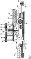
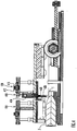
- FIGS 2-8 illustrate the modified flash station in accordance with the present invention. Only modifications from the flash station disclosed in the '486 patent are shown or described. Component parts of the flash station that correspond to the same component parts of the flash station disclosed in the '486 patent are numbered with the same reference numbers as used in the '486 patent.
- FIG 2 illustrates a mounting plate 94 carried on the outside circumference of a rotatable wheel 24, the wheel 24 rotatable about an axis of rotation perpendicular to the plane of the drawing sheet as viewed in Figure 2 .
- the mounting plate 94 carries a log holder 98 and a set of flash punch tooling 112.
- An untrimmed plastic log H is shown carried by the log holder 98.
- the flash punch tooling 112 includes a flash punch assembly 114, a guillotine assembly or blow dome trim assembly 410 adjacent the flash punch assembly 114, and a drive assembly 116.
- the flash punch assembly 114 and the blow dome trim assembly 410 are mounted on a common carrier or top plate 140 connected to the drive assembly 116 for conjoint movement.
- the drive assembly 116 includes a cam follower 126 guided by a stationary cam guide 120 extending circumferentially around a portion of the outer periphery of the wheel 24. The drive assembly 116 drives the flash punch assembly 114 and the blow dome trim assembly 410 towards and away from the log holder 98.
- a second drive assembly drives the flash punch assembly 114.
- the second drive assembly includes a roller cam follower 162 attached to the top of the flash punch assembly 114.
- the cam follower 162 is guided by a stationary cam 120 having a guide surface 164 extending circumferentially along a portion of the outer periphery of the wheel 24.
- the second drive assembly drives the flash punch assembly 114 from a retracted position shown in Figure 2 through a stroke to trim the flash from the plastic log H.
- a third drive assembly similar to the second drive assembly drives the blow dome trim assembly 410.
- the third drive assembly includes a roller cam follower 412 attached to the top of the blow dome trim assembly 410 and guided by a stationary guide surface 413 (similar to the guide surface 164) on the cam 120.
- the third drive assembly drives the blow dome trim assembly 410 from a retracted position shown in Figure 2 through a stroke to trim the bottle log blow dome J .
- the log holder 98 includes a bottle neck and blow dome support 104 that supports the neck I and the blow dome J of the bottle H.
- the support 104 is similar to the support 104 disclosed in the '486 patent, but is modified to enable trimming of the blow dome.
- the top surface 414 of the support portion 416 supporting the neck I conforms to the shape of the neck, see Figure 6 .
- the surface 414 extends less than 180 degrees around the bottom half of the neck and the support portion 416 has a width less than the diameter of the neck. This prevents the thickness of the flash K from interfering with the seating of the neck in the support portion 416, and enables the extreme outer sides of the neck above the support portion 416 to extend outwardly and proud of the support portion 416.
- the illustrated neck support surface 414 is a smooth surface.
- the surface 414 could include a bead or could be profiled to conform to the neck threads to assist in positioning the bottle H in the log holder 98.
- the blow dome trim assembly 410 includes a top plate 418 and a bottom plate 420, similar in function to the top plate 146 and the bottom plate 148 of the flash punch assembly 114.
- the top plate 418 carries the roller cam follower 412.
- the plates 418, 420 are movable together along a linear stroke path defined by a set of elongate guide posts 422.
- Attached to the upper side of the bottom plate 420 is a double-acting pneumatic cylinder 424. Extending out of the cylinder and through a hole in the plate 420 is a piston rod 426 that carries a conventional guillotine-type blade 428.
- Attached to the bottom side of the plate 420 immediately adjacent the blade opening is an upper neck support plate 430.
- the support plate 430 has a thickness equal to the length of the neck I .
- the neck support plate 430 has a bottom surface 432 that conforms to the shape of the neck, see Figure 7 .
- the surface 432 has an arcuate portion 434 that extends about 180 degrees, and two parallel wall portions 436 that extend vertically a short distance from the ends of the arcuate portion 434.
- Figure 2 illustrates the flash station immediately after the log holder 98 receives the plastic bottle log H to be trimmed.
- the cam follower 126 has placed the flash punch assembly 114 and the blow dome trim assembly 410 in their retracted positions.
- the assemblies 114 and 410 are each in their return or raised positions along their respective stroke paths.
- the pneumatic cylinder 424 is also in its retracted position.
- the drive assembly 116 is modified from that shown in the '486 patent to provide for a longer stroke that enables the cam follower 126 to move the blow dome assembly 410 over the bottle log H as shown in Figure 4 .
- the flash punch assembly 114 has sufficient clearance to move over the body of the body log H.
- the neck support plate 430 is spaced from and located immediately above the neck I of the bottle log. See also Figure 7 .
- the pneumatic cylinder 424 is in its retracted condition, with the guillotine blade 428 immediately above the connection of the blow dome J with the neck I .
- the cam follower 412 then forces the blow dome trim assembly 410 to move in its stroke along the guide posts 422 to a lowered position shown in Figure 5 .
- the neck ring I is closely received within the neck support plate 430 as shown in Figure 8 , with the neck support plate side walls 436 extending down to the top of the of the log holder neck support portion 416.
- the curved wall sections 414, 434 of the neck support portion 416 and the neck support plate 430 provide essentially continuous support of the entire circumference of the neck ring I .
- the pneumatic cylinder is actuated to quickly extend the piston rod 426 and move the guillotine blade 428 through the log H , severing the blow dome J from the neck I .
- the neck support plate 430 helps support the blade 428 as the blade cuts through the blow dome to assure a clean cut perpendicular to the longitudinal axis of the neck.
- a recess or blade groove 438 in the neck support plate 104 allows the guillotine blade 430 to pass through the entire thickness of the blow dome.
- the pneumatic cylinder 424 is then actuated to retract the piston rod and the cam follower 412 returns the blow dome trim assembly to its raised position.
- the cam follower 126 then returns the assemblies 114, 410 back to their retracted positions shown in Figure 2 for ejection of the flash-trimmed and blow dome-trimmed bottle log from the log holder 98.
- Wheel 24 is designed to receive untrimmed logs from a first transfer wheel 22 and to discharge trimmed bottles to a second transfer wheel 26, see Figure 9 .
- the wheels 22, 24, and 26 operate at a high production speed with an output of 200 trimmed bottles per minute.
- a description of the transfer wheels 22 and 28, and how logs and trimmed bottles are transferred between the transfer wheels 22, 28 and the wheel 24 is provided in the '486 patent and so will not be repeated here.
- Figure 9 illustrates the path of movement of log H from an infeed conveyor 32 to a discharge conveyor 34.
- Arcuate path 320 extends from infeed end 322 where the log is picked up by wheel 22 from conveyor 32 and extends continuously around arcuate portions 324, 326, and 328 on wheels 22, 24, and 26 respectively to discharge point 330 where the trimmed bottles are placed on discharge conveyor 34.
- Wheels 22, 24, and 26 support the logs and bottles in nests located a distance r from the axis of rotation of the wheel. Wheels 22, 24, and 26 are rotated at the same circumferential speed so that the logs are moved along path 320 at the same speed.
- the logs are held on the wheels 22, 24, and 26 with the neck axes D extending transversely to the direction of movement along path 320 and parallel to the rotational axes of the wheels.
- Figures 10-12 illustrate a second embodiment blow dome trim assembly 510 that can replace the trim assembly 410.
- This embodiment simplifies construction of the blow dome trim assembly by eliminating the pneumatic cylinder 424 - the radial stroke of the guillotine blade 428 is equal to the radial stroke of the cam follower 416.
- the blow dome trim assembly 510 includes a slide plate 512 attached to the top plate 418 and extending between the guide posts 422.
- the elongate guillotine blade 428 is fixedly attached to the slide plate 512 for conjoint movement with the plate 512 and extends parallel with the guide posts 422.
- the lower, cutting end portion of the guillotine blade 428 extends outwardly beyond the slide plate 512.
- An upper mounting bracket 514 is fixedly attached to the plate 512 on the same side of the plate 512 as the guillotine blade 428.
- the bracket 514 carries a pair of secondary guide posts 516 that are closely received in bores of the bracket 514 and enable relative movement of the bracket 514 along the length of the guide posts 516.
- Fixedly attached to the lower ends of the guide posts 516 is the upper neck support plate 430. Compression springs 518 extending along the posts 516 urge the neck support plate 430 away from the bracket 514.
- the guide posts 516 are spaced from the side plate 512 such that the neck support plate 430 is immediately adjacent the guillotine blade 428.
- a pair of elongate rods 520 extend through bores in the neck support plate 420 and are aligned outwardly of and parallel with the guide posts 516.
- the rods 520 also extend through bores in a fixed bracket 522 that permit relative axial movement of the bracket 522 along the rods 520.
- the bracket 522 is fixed with respect to the carrier plate 140 and is at a fixed radial distance from the log holder 98 during operation of the blow dome trim assembly 510.
- Mounted on each rod 520 on the opposite side of the bracket 522 from the neck support plate 430 is a set of stop nuts 524 that will engage the fixed bracket 522 and limit relative axial movement of the neck support plate 430 away from the fixed bracket 522.
- Figure 10 illustrates the blow trim assembly 510 in its raised position, similar to the position of the blow trim assembly 410 shown in Figure 4 .
- the springs 518 locate the upper neck support plate 430 away from the upper mounting bracket 514, with the neck support surface 432 spaced outwardly beyond the cutting edges of the guillotine blade 428.
- the stop nuts 524 are spaced away from the fixed bracket 522.
- the cam follower 412 forces the blow dome trim assembly 510 to move in its stroke along the guide posts 422.
- the springs 516 force the upper neck support plate 430 to move with the upper bracket 514 along the stroke until the stop nuts 524 contact the fixed bracket 522 as shown in Figure 11 , preventing further movement of the upper neck support plate 430 along the stroke.
- the neck support plate 430 is closely spaced from the neck I and cooperates with the log holder neck support portion 416 to provide essentially continuous support of the entire circumference of the neck ring I as previously described during the remainder of the stroke.
- the guillotine blade 428 is spaced slightly away from the neck ring I .
- the cam follower 412 continues its downward stroke from the intermediate position shown in Figure 11 to the lowered position shown in Figure 12 .
- the neck support plate 430 does not move along this portion of the stroke.
- the springs 518 are compressed between the neck support plate 430 and upper bracket 514 with continued movement of the slide plate 512 along the stroke.
- the guillotine blade 428 moves through the log H , severing the blow dome J from the neck I .
- the radial stroke length of the cam follower 412 when used with the trim assembly 510 is longer than when used with the trim assembly 410 since the stroke must be sufficient on its own to move the guillotine blade 428 through the log H.
- the cam follower 412 After trimming the blow dome, the cam follower 412 then returns the blow dome trim assembly 510 back to the raised position shown in Figure 10 .
- the springs 516 urge the neck support plate 430 away from the upper bracket 514, returning the neck support plate 430 to its original position relative to the bracket 514.
- the cam follower 126 then returns the entire assembly to its retracted position (corresponding to the position shown in Figure 2 ) for ejection of the trimmed log from the log holder 98.
- the trim station could include only a blow dome trim assembly 410 or 510 and the flash punch trim assembly 114 is eliminated.
- the log holder 98 can be stationary rather than mounted on a wheel.
- the illustrated neck support surfaces are concave surfaces and closely conform to the convex shape of the bottle neck L ; the neck support surfaces can be flat or even convex surfaces in other embodiments in order to conform to other possible shapes of the bottle neck.
- the illustrated embodiments illustrate trimming flash from the plastic log in addition to trimming the blow dome from the neck of the plastic log.
- other trimming operations known in the blow-molded plastic bottle art could be performed in addition to trimming the blow dome.
Landscapes
- Engineering & Computer Science (AREA)
- Manufacturing & Machinery (AREA)
- Mechanical Engineering (AREA)
- Blow-Moulding Or Thermoforming Of Plastics Or The Like (AREA)
- Processing And Handling Of Plastics And Other Materials For Molding In General (AREA)
- Moulds For Moulding Plastics Or The Like (AREA)
Claims (20)
- Méthode de découpe d'un dôme soufflé d'un goulot d'une bouteille en plastique formant une partie d'une barre moulée par soufflage en plastique déchargée d'un moule de soufflage, le goulot s'étendant le long d'un axe, la méthode comprenant les étapes de :(a) placement d'une barre non coupée (H) sur un porte-barre (98) et d'installation d'un ensemble de guillotine (410) dans une position rétractée, éloigné du porte-barre pendant que la barre est placée sur le porte-barre, l'ensemble de guillotine comprenant un support (140), une lame (162) pour couper le dôme soufflé du goulot de bouteille, et une plaque de soutien de goulot (430), la lame et la plaque de soutien de goulot étant montées sur le support pour permettre un mouvement conjoint avec le support ;(b) déplacement du support, de la position rétractée vers une position étendue, en positionnant l'ensemble de guillotine de manière adjacente au porte-barre, après que la barre ait été placée sur le porte-barre, la plaque de soutien de goulot et la lame étant espacées d'un premier côté de la barre en plastique et recouvrant celui-ci dans une direction perpendiculaire à l'axe du goulot quand l'ensemble de guillotine est adjacent au porte-barre ;(c) déplacement de la plaque de soutien de goulot sur une distance prédéterminée vers la barre en plastique et d'arrêt de la plaque de soutien de goulot de manière adjacente au goulot après ce mouvement ;(d) déplacement de la lame vers et à travers la barre en plastique, après la réalisation de l'étape (c), pour couper le dôme soufflé du goulot ;(e) déplacement de l'ensemble de guillotine de sa position étendue adjacente au porte-barre vers la position rétractée éloignée du porte-barre après la réalisation de l'étape (d) ; et(f) retrait de la barre découpée du porte-barre après réalisation de l'étape (e).
- Méthode selon la revendication 1, dans laquelle la plaque de soutien de goulot représente un premier soutien de goulot et le porte-barre comprend un second soutien de goulot (414) et l'étape (a) comprend l'étape de :(g) placement du goulot de la barre non coupée de manière adjacente au second soutien de goulot.
- Méthode selon la revendication 2, dans laquelle les premier et second soutiens de goulot soutiennent essentiellement toute la périphérie extérieure du goulot après la réalisation de l'étape (c).
- Méthode selon la revendication 1, dans laquelle l'ensemble de guillotine comprend un galet suiveur (412) guidé par une surface de came (413), la plaque de soutien de goulot étant fixée par rapport au galet suiveur pour permettre un mouvement conjoint avec le galet suiveur.
- Méthode selon la revendication 4, dans laquelle la lame est attachée à une commande (424) qui déplace la lame relativement à la plaque de soutien de goulot, et l'étape (d) comprend l'étape de :(h) actionnement de la commande pour déplacer la lame relativement au soutien de goulot et à travers la barre en plastique.
- Méthode selon la revendication 1, dans laquelle l'ensemble de guillotine comprend un galet suiveur (412) guidé par une surface de came (413) pour déplacer le galet suiveur vers et loin du porte-barre, la lame étant fixée par rapport au galet suiveur pour permettre un mouvement conjoint avec le galet suiveur.
- Méthode selon la revendication 6, dans laquelle l'ensemble de guillotine comprend un élément (522) fixé par rapport au support, et l'étape (c) comprend l'étape de :(i) mise en prise d'un élément d'arrêt (524) opérationnellement raccordé à la plaque de soutien de goulot contre l'élément fixe, pour arrêter le mouvement relatif de la plaque de soutien de goulot par rapport au porte-barre.
- Méthode selon la revendication 1, comprenant les étapes de :(j) déplacement continu d'un porte-barre et d'un ensemble de guillotine ensemble le long d'un chemin (24) ayant un emplacement d'admission et un emplacement de décharge ;(k) lancement de l'étape (a) quand le porte-barre est à l'emplacement d'admission ; et(l) lancement de l'étape (b) quand le porte-barre est à l'emplacement de décharge.
- Méthode selon la revendication 8, dans laquelle l'étape (g) comprend l'étape de :(m) rotation du porte-barre et l'ensemble de guillotine autour d'un axe commun selon un rayon (r).
- Méthode selon la revendication 1, dans laquelle l'ensemble de guillotine comprend un galet suiveur (412) guidé par une surface de came (413) pour déplacer le galet suiveur vers et loin du porte-barre, la plaque de soutien de goulot étant fixée par rapport au galet suiveur pour permettre un mouvement conjoint avec le galet suiveur.
- Méthode selon la revendication 1, dans laquelle la découpe du dôme soufflé de la barre en plastique représente une opération de découpe, la méthode comprenant l'étape de :(n) réalisation d'une seconde opération de découpe sur la barre en plastique pendant que la barre en plastique est sur le porte-barre.
- Ensemble pour découper un dôme soufflé d'un goulot d'une bouteille en plastique formant une partie d'une barre moulée par soufflage en plastique, déchargée d'un moule de soufflage, le goulot s'étendant le long d'un axe, l'ensemble comprenant :un porte-barre (98), une lame (428), et une plaque de soutien de goulot (430), la lame comprenant un bord de coupe ;une commande de lame (424, 412, 413) opérationnellement raccordée à la lame pour le déplacement de la lame, entre des positions levée et baissée de la lame, la position inférieure étant espacée de la position levée ; et étant caractérisée par :un support (140) ;le support étant mobile entre une position rétractée et une position étendue, espacée de la position rétractée, la lame et la plaque de soutien de goulot étant supportées par le support pour permettre un mouvement avec le support, entre les positions rétractée et étendue, dans lequel la lame et la plaque de soutien de goulot sont adjacentes au porte-barre et seraient espacées d'une barre portée dans le port-barre et recouvraient celle-ci quand le support est dans la position étendue, et dans lequel la lame et la plaque de soutien de goulot sont éloignées du porte-barre quand le support est dans la position rétractée pour permettre l'éjection de la barre du porte-barre :une commande de support (116) opérationnellement raccordée au support pour le déplacement du support entre lesdites positions rétractée et étendue ;la plaque de soutien de goulot étant mobile par rapport au support entre une position levée et une position baissée, espacée de la position levée de la plaque ;la lame étant mobile par rapport au support, le long d'une course de la lame entre la position levée et la position baissée, le bord de coupe de la lame étant positionné sur une extrémité d'attaque de la lame alors que la lame se déplace de la position levée à la position baissée ;une commande de plaque (412, 413) opérationnellement raccordée à la plaque de soutien de goulot pour le déplacement de la plaque de soutien de goulot, entre lesdites positions levée et baissée de la plaque de soutien de goulot ;la lame et la plaque de soutien de goulot étant adaptées pour être espacées du porte-barre chacune sur une première distance respective, dans une première direction, quand la lame et la plaque de soutien de goulot sont chacune dans la position levée ;la lame et la plaque de soutien de goulot étant adaptées pour recouvrir le porte-barre dans ladite première direction, quand le support est dans la position étendue ;la lame étant adaptée pour se déplacer vers ledit porte-barre quand la lame se déplace de la position levée à la position baissée, quand le support est dans la position étendue ;la plaque de soutien de goulot étant adaptée pour se déplacer vers le porte-barre, quand ladite plaque de soutien de goulot se déplace de la position levée à la position baissée, quand le support est dans la position étendue ; etla course de la lame étant capable de passer à travers une barre portée par le porte-barre quand le support est dans la position étendue ;la lame et la plaque de soutien de goulot étant éloignées du porte-barre quand le support est dans la position rétractée, pour permettre l'éjection de la barre du porte-barre.
- Ensemble selon la revendication 12, dans lequel la plaque de soutien de goulot fait face à une partie du porte-barre quand la plaque de soutien de goulot est dans la position baissée et le support est dans la position étendue, la plaque de soutien de goulot et la partie de porte-barre étant configurées pour soutenir en coopération un goulot d'une bouteille en plastique.
- Ensemble selon la revendication 12, dans lequel la commande de lame comprend un cylindre (424) et une tige de piston (426), la lame étant attachée à la tige de piston.
- Ensemble selon la revendication 12, dans lequel la commande de lame et la commande de plaque comprennent en commun un galet suiveur (412) et une surface de came (413) guidant ledit galet suiveur.
- Ensemble selon la revendication 12, dans lequel le support est monté sur une roue (24) qui est adaptée pour tourner autour d'un axe.
- Ensemble selon la revendication 12, dans lequel la commande de lame comprend au moins un ressort (518) portant contre la plaque de soutien de goulot, la plaque de soutien de goulot étant relativement mobile par rapport audit ressort.
- Ensemble selon la revendication 12, comprenant un porte-barre (24) qui est adapté pour déplacer de manière continue le porte-barre le long d'un chemin fermé.
- Ensemble selon la revendication 12, dans lequel le support est espacé du porte-barre et le support, la lame, et la plaque de soutien de goulot ne recouvrent pas le porte-barre dans ladite première direction quand le support est dans la position rétractée.
- Ensemble selon la revendication 12, dans lequel le support supporte également un ensemble de poinçon éclair (114).
Applications Claiming Priority (2)
| Application Number | Priority Date | Filing Date | Title |
|---|---|---|---|
| US34767410P | 2010-05-24 | 2010-05-24 | |
| PCT/US2011/036168 WO2011149679A2 (fr) | 2010-05-24 | 2011-05-12 | Dispositif de coupe de barre pour bouteille en matière plastique et procédé |
Publications (3)
| Publication Number | Publication Date |
|---|---|
| EP2576182A2 EP2576182A2 (fr) | 2013-04-10 |
| EP2576182A4 EP2576182A4 (fr) | 2015-05-27 |
| EP2576182B1 true EP2576182B1 (fr) | 2016-12-14 |
Family
ID=45004656
Family Applications (1)
| Application Number | Title | Priority Date | Filing Date |
|---|---|---|---|
| EP11787114.5A Active EP2576182B1 (fr) | 2010-05-24 | 2011-05-12 | Procédé et dispositif de coupe de barre pour bouteille en matière plastique moulée par soufflage |
Country Status (11)
| Country | Link |
|---|---|
| US (1) | US9308685B2 (fr) |
| EP (1) | EP2576182B1 (fr) |
| JP (1) | JP2013527063A (fr) |
| KR (1) | KR20130082097A (fr) |
| CN (1) | CN102905873B (fr) |
| AU (1) | AU2011258740B2 (fr) |
| BR (1) | BR112012030038A2 (fr) |
| CA (1) | CA2799395A1 (fr) |
| ES (1) | ES2615897T3 (fr) |
| MX (1) | MX2012013516A (fr) |
| WO (1) | WO2011149679A2 (fr) |
Families Citing this family (3)
| Publication number | Priority date | Publication date | Assignee | Title |
|---|---|---|---|---|
| JP6268755B2 (ja) * | 2013-05-31 | 2018-01-31 | キョーラク株式会社 | タンク及びその製造方法 |
| CN104385508B (zh) * | 2014-10-10 | 2017-02-01 | 珀尔曼机电(昆山)有限公司 | 一种毛边去除装置 |
| CN118493752B (zh) * | 2024-05-23 | 2025-03-18 | 山东创佳包装制品有限公司 | 一种带有飞边去除组件的注塑成型设备 |
Family Cites Families (31)
| Publication number | Priority date | Publication date | Assignee | Title |
|---|---|---|---|---|
| US2988776A (en) * | 1959-07-27 | 1961-06-20 | Owens Illinois Glass Co | Method and apparatus for trimming blown hollow plastic articles |
| BE639719A (fr) * | 1962-11-08 | |||
| US3319498A (en) * | 1963-08-13 | 1967-05-16 | Owens Illinois Inc | Plastic bottle trimming method |
| US3417428A (en) * | 1964-12-09 | 1968-12-24 | Hoover Ball & Bearing Co | Apparatus for trim finishing blow molded containers |
| FR1499446A (fr) * | 1966-09-16 | 1967-10-27 | Dispositif de coupe d'objets en matière peu rigide ou molle mus par un transporteur | |
| FR1596477A (fr) | 1968-06-17 | 1970-06-22 | ||
| US3570087A (en) | 1969-01-27 | 1971-03-16 | Robert J Palsa | Bottle trimming apparatus |
| US3656385A (en) * | 1970-03-10 | 1972-04-18 | Certain Teed Prod Corp | Apparatus for machine forming extruded plastic siding |
| US3797985A (en) * | 1972-02-22 | 1974-03-19 | Continental Can Co | Excess parison remover |
| JPS6020169B2 (ja) | 1978-12-11 | 1985-05-20 | キユーピー株式会社 | 合成樹脂製容器の口部余剰部切除装置 |
| US4361531A (en) | 1979-03-28 | 1982-11-30 | Doric Foods Corporation | Container molding and trimming method and apparatus |
| US4653368A (en) * | 1985-12-06 | 1987-03-31 | Riera John F | Tube cutoff die set |
| US4834643A (en) | 1988-05-27 | 1989-05-30 | Graham Engineering Corporation | Blow molded bottle extraction, trimming and discharge apparatus |
| US5167968A (en) * | 1991-03-11 | 1992-12-01 | Plastipak Packaging, Inc. | Apparatus for finishing a blow molding |
| US5202135A (en) * | 1991-04-09 | 1993-04-13 | Ring Can Corporation | Bottle flash trimming apparatus |
| US5617768A (en) * | 1995-05-11 | 1997-04-08 | M.C. Molds Inc. | Trimmer for removing scraping from tops of plastic bottles |
| CA2220397A1 (fr) * | 1996-11-26 | 1998-05-26 | Dennis L. Dundas | Bouteille moulee par soufflage et transporteur |
| US5967910A (en) | 1997-09-15 | 1999-10-19 | Lin; Mike | Baseball hitting exerciser |
| JPH11240065A (ja) * | 1998-02-25 | 1999-09-07 | Kao Corp | ブロー成形装置 |
| US5967010A (en) | 1998-04-10 | 1999-10-19 | Cambridge Industries, Inc. | Cutting apparatus and cutting process for hollow plastic molded articles |
| DE29808312U1 (de) | 1998-05-11 | 1998-08-13 | cpm GmbH, 49124 Georgsmarienhütte | Trennmesser |
| JP2000263636A (ja) * | 1999-03-16 | 2000-09-26 | Tahara:Kk | 薄肉容器の栓体インサート成形方法 |
| US6360414B1 (en) * | 2000-05-24 | 2002-03-26 | Uniloy Milacron Inc. | Rotary deflashing apparatus |
| US20040011169A1 (en) * | 2002-07-22 | 2004-01-22 | Delaware Capital Formation, Inc. | Apparatus for trimming the dome area of a wide mouth blow molded plastic container |
| US7093525B2 (en) | 2002-09-13 | 2006-08-22 | Autotech, Inc. | Chipless trimming of plastic bottles |
| BR0300672A (pt) * | 2003-03-07 | 2004-11-16 | Logoplaste Do Brasil Ltda | Processo e molde para moldagem de embalagens plásticas |
| US7037101B2 (en) * | 2003-04-15 | 2006-05-02 | Graham Packing Company, L.P. | Center cylinder ejection assist |
| US20050284275A1 (en) * | 2004-06-28 | 2005-12-29 | Graham Packaging Company, L.P. | Knife for trimming plastic container |
| US7441486B2 (en) * | 2004-10-01 | 2008-10-28 | Graham Engineering Corp. | Bottle trimmer and method |
| US20080314216A1 (en) * | 2007-06-20 | 2008-12-25 | Andres Ignacio Delgado | Tire cord cutting apparatus |
| US7607375B2 (en) * | 2007-06-29 | 2009-10-27 | Graham Packaging Company, L.P. | Apparatus and method for attaching spouts to containers |
-
2011
- 2011-05-12 CN CN201180025651.0A patent/CN102905873B/zh active Active
- 2011-05-12 WO PCT/US2011/036168 patent/WO2011149679A2/fr not_active Ceased
- 2011-05-12 AU AU2011258740A patent/AU2011258740B2/en not_active Ceased
- 2011-05-12 ES ES11787114.5T patent/ES2615897T3/es active Active
- 2011-05-12 BR BR112012030038A patent/BR112012030038A2/pt not_active IP Right Cessation
- 2011-05-12 EP EP11787114.5A patent/EP2576182B1/fr active Active
- 2011-05-12 US US13/696,443 patent/US9308685B2/en active Active
- 2011-05-12 JP JP2013512646A patent/JP2013527063A/ja not_active Abandoned
- 2011-05-12 CA CA 2799395 patent/CA2799395A1/fr not_active Abandoned
- 2011-05-12 MX MX2012013516A patent/MX2012013516A/es not_active Application Discontinuation
- 2011-05-12 KR KR20127033488A patent/KR20130082097A/ko not_active Withdrawn
Non-Patent Citations (1)
| Title |
|---|
| None * |
Also Published As
| Publication number | Publication date |
|---|---|
| US20130047806A1 (en) | 2013-02-28 |
| KR20130082097A (ko) | 2013-07-18 |
| WO2011149679A2 (fr) | 2011-12-01 |
| WO2011149679A3 (fr) | 2012-04-05 |
| BR112012030038A2 (pt) | 2016-08-02 |
| CN102905873A (zh) | 2013-01-30 |
| AU2011258740A1 (en) | 2012-11-29 |
| AU2011258740B2 (en) | 2014-01-09 |
| JP2013527063A (ja) | 2013-06-27 |
| ES2615897T3 (es) | 2017-06-08 |
| CA2799395A1 (fr) | 2011-12-01 |
| EP2576182A4 (fr) | 2015-05-27 |
| CN102905873B (zh) | 2015-08-19 |
| US9308685B2 (en) | 2016-04-12 |
| MX2012013516A (es) | 2013-01-24 |
| EP2576182A2 (fr) | 2013-04-10 |
Similar Documents
| Publication | Publication Date | Title |
|---|---|---|
| US7752947B2 (en) | Bottle trimmer and method | |
| KR970061494A (ko) | 에이펙스 필러를 비드 링에 제공하기 위한 장치 | |
| US4526074A (en) | High-speed apparatus and method for trimming thermoformed articles | |
| AU2011258740B2 (en) | Plastic bottle log trimmer and method | |
| US20170043495A1 (en) | Three dimensional part rotary die cutting mechanism and method of operating the same | |
| US3972299A (en) | Can body trimmer | |
| JP2620705B2 (ja) | 管状物品をトリミングする装置 | |
| US4815348A (en) | Apparatus for trimming a flanged end of a tubular article | |
| EP1283772B1 (fr) | Dispositif rotatif a ebavurer | |
| CN204035295U (zh) | 实现数控转塔冲床直角剪切的可分度模具组合系统 | |
| US20070084324A1 (en) | Slicer for circular formed bakery products | |
| CN104028611B (zh) | 实现数控转塔冲床直角剪切的可分度模具组合系统 | |
| CN214867748U (zh) | 一种药用铝瓶用毛边修除装置 | |
| JP4277297B2 (ja) | 野菜類の型抜装置 | |
| SU1588511A1 (ru) | Способ изготовлени деталей стержневого типа и модуль автоматической линии дл его осуществлени | |
| KR200268216Y1 (ko) | 금속반제품의 절단기 | |
| JPH02250709A (ja) | 筒体の切断方法と装置 |
Legal Events
| Date | Code | Title | Description |
|---|---|---|---|
| PUAI | Public reference made under article 153(3) epc to a published international application that has entered the european phase |
Free format text: ORIGINAL CODE: 0009012 |
|
| 17P | Request for examination filed |
Effective date: 20121129 |
|
| AK | Designated contracting states |
Kind code of ref document: A2 Designated state(s): AL AT BE BG CH CY CZ DE DK EE ES FI FR GB GR HR HU IE IS IT LI LT LU LV MC MK MT NL NO PL PT RO RS SE SI SK SM TR |
|
| DAX | Request for extension of the european patent (deleted) | ||
| A4 | Supplementary search report drawn up and despatched |
Effective date: 20150430 |
|
| RIC1 | Information provided on ipc code assigned before grant |
Ipc: B29C 49/74 20060101AFI20150423BHEP |
|
| 17Q | First examination report despatched |
Effective date: 20160411 |
|
| GRAP | Despatch of communication of intention to grant a patent |
Free format text: ORIGINAL CODE: EPIDOSNIGR1 |
|
| RIC1 | Information provided on ipc code assigned before grant |
Ipc: B29C 49/74 20060101AFI20160622BHEP Ipc: B26D 7/26 20060101ALN20160622BHEP Ipc: B29L 31/00 20060101ALN20160622BHEP |
|
| INTG | Intention to grant announced |
Effective date: 20160708 |
|
| GRAS | Grant fee paid |
Free format text: ORIGINAL CODE: EPIDOSNIGR3 |
|
| GRAA | (expected) grant |
Free format text: ORIGINAL CODE: 0009210 |
|
| AK | Designated contracting states |
Kind code of ref document: B1 Designated state(s): AL AT BE BG CH CY CZ DE DK EE ES FI FR GB GR HR HU IE IS IT LI LT LU LV MC MK MT NL NO PL PT RO RS SE SI SK SM TR |
|
| REG | Reference to a national code |
Ref country code: GB Ref legal event code: FG4D |
|
| REG | Reference to a national code |
Ref country code: CH Ref legal event code: EP |
|
| REG | Reference to a national code |
Ref country code: IE Ref legal event code: FG4D |
|
| REG | Reference to a national code |
Ref country code: AT Ref legal event code: REF Ref document number: 853180 Country of ref document: AT Kind code of ref document: T Effective date: 20170115 |
|
| REG | Reference to a national code |
Ref country code: DE Ref legal event code: R096 Ref document number: 602011033446 Country of ref document: DE |
|
| PG25 | Lapsed in a contracting state [announced via postgrant information from national office to epo] |
Ref country code: LV Free format text: LAPSE BECAUSE OF FAILURE TO SUBMIT A TRANSLATION OF THE DESCRIPTION OR TO PAY THE FEE WITHIN THE PRESCRIBED TIME-LIMIT Effective date: 20161214 |
|
| REG | Reference to a national code |
Ref country code: LT Ref legal event code: MG4D |
|
| REG | Reference to a national code |
Ref country code: NL Ref legal event code: MP Effective date: 20161214 |
|
| PG25 | Lapsed in a contracting state [announced via postgrant information from national office to epo] |
Ref country code: SE Free format text: LAPSE BECAUSE OF FAILURE TO SUBMIT A TRANSLATION OF THE DESCRIPTION OR TO PAY THE FEE WITHIN THE PRESCRIBED TIME-LIMIT Effective date: 20161214 Ref country code: GR Free format text: LAPSE BECAUSE OF FAILURE TO SUBMIT A TRANSLATION OF THE DESCRIPTION OR TO PAY THE FEE WITHIN THE PRESCRIBED TIME-LIMIT Effective date: 20170315 Ref country code: NO Free format text: LAPSE BECAUSE OF FAILURE TO SUBMIT A TRANSLATION OF THE DESCRIPTION OR TO PAY THE FEE WITHIN THE PRESCRIBED TIME-LIMIT Effective date: 20170314 Ref country code: LT Free format text: LAPSE BECAUSE OF FAILURE TO SUBMIT A TRANSLATION OF THE DESCRIPTION OR TO PAY THE FEE WITHIN THE PRESCRIBED TIME-LIMIT Effective date: 20161214 |
|
| REG | Reference to a national code |
Ref country code: AT Ref legal event code: MK05 Ref document number: 853180 Country of ref document: AT Kind code of ref document: T Effective date: 20161214 |
|
| PG25 | Lapsed in a contracting state [announced via postgrant information from national office to epo] |
Ref country code: FI Free format text: LAPSE BECAUSE OF FAILURE TO SUBMIT A TRANSLATION OF THE DESCRIPTION OR TO PAY THE FEE WITHIN THE PRESCRIBED TIME-LIMIT Effective date: 20161214 Ref country code: RS Free format text: LAPSE BECAUSE OF FAILURE TO SUBMIT A TRANSLATION OF THE DESCRIPTION OR TO PAY THE FEE WITHIN THE PRESCRIBED TIME-LIMIT Effective date: 20161214 Ref country code: HR Free format text: LAPSE BECAUSE OF FAILURE TO SUBMIT A TRANSLATION OF THE DESCRIPTION OR TO PAY THE FEE WITHIN THE PRESCRIBED TIME-LIMIT Effective date: 20161214 |
|
| REG | Reference to a national code |
Ref country code: ES Ref legal event code: FG2A Ref document number: 2615897 Country of ref document: ES Kind code of ref document: T3 Effective date: 20170608 |
|
| PG25 | Lapsed in a contracting state [announced via postgrant information from national office to epo] |
Ref country code: NL Free format text: LAPSE BECAUSE OF FAILURE TO SUBMIT A TRANSLATION OF THE DESCRIPTION OR TO PAY THE FEE WITHIN THE PRESCRIBED TIME-LIMIT Effective date: 20161214 |
|
| PG25 | Lapsed in a contracting state [announced via postgrant information from national office to epo] |
Ref country code: EE Free format text: LAPSE BECAUSE OF FAILURE TO SUBMIT A TRANSLATION OF THE DESCRIPTION OR TO PAY THE FEE WITHIN THE PRESCRIBED TIME-LIMIT Effective date: 20161214 Ref country code: RO Free format text: LAPSE BECAUSE OF FAILURE TO SUBMIT A TRANSLATION OF THE DESCRIPTION OR TO PAY THE FEE WITHIN THE PRESCRIBED TIME-LIMIT Effective date: 20161214 Ref country code: CZ Free format text: LAPSE BECAUSE OF FAILURE TO SUBMIT A TRANSLATION OF THE DESCRIPTION OR TO PAY THE FEE WITHIN THE PRESCRIBED TIME-LIMIT Effective date: 20161214 Ref country code: IS Free format text: LAPSE BECAUSE OF FAILURE TO SUBMIT A TRANSLATION OF THE DESCRIPTION OR TO PAY THE FEE WITHIN THE PRESCRIBED TIME-LIMIT Effective date: 20170414 Ref country code: SK Free format text: LAPSE BECAUSE OF FAILURE TO SUBMIT A TRANSLATION OF THE DESCRIPTION OR TO PAY THE FEE WITHIN THE PRESCRIBED TIME-LIMIT Effective date: 20161214 |
|
| PG25 | Lapsed in a contracting state [announced via postgrant information from national office to epo] |
Ref country code: LU Free format text: LAPSE BECAUSE OF NON-PAYMENT OF DUE FEES Effective date: 20170531 Ref country code: BG Free format text: LAPSE BECAUSE OF FAILURE TO SUBMIT A TRANSLATION OF THE DESCRIPTION OR TO PAY THE FEE WITHIN THE PRESCRIBED TIME-LIMIT Effective date: 20170314 Ref country code: BE Free format text: LAPSE BECAUSE OF FAILURE TO SUBMIT A TRANSLATION OF THE DESCRIPTION OR TO PAY THE FEE WITHIN THE PRESCRIBED TIME-LIMIT Effective date: 20161214 Ref country code: PT Free format text: LAPSE BECAUSE OF FAILURE TO SUBMIT A TRANSLATION OF THE DESCRIPTION OR TO PAY THE FEE WITHIN THE PRESCRIBED TIME-LIMIT Effective date: 20170414 Ref country code: PL Free format text: LAPSE BECAUSE OF FAILURE TO SUBMIT A TRANSLATION OF THE DESCRIPTION OR TO PAY THE FEE WITHIN THE PRESCRIBED TIME-LIMIT Effective date: 20161214 Ref country code: SM Free format text: LAPSE BECAUSE OF FAILURE TO SUBMIT A TRANSLATION OF THE DESCRIPTION OR TO PAY THE FEE WITHIN THE PRESCRIBED TIME-LIMIT Effective date: 20161214 Ref country code: AT Free format text: LAPSE BECAUSE OF FAILURE TO SUBMIT A TRANSLATION OF THE DESCRIPTION OR TO PAY THE FEE WITHIN THE PRESCRIBED TIME-LIMIT Effective date: 20161214 |
|
| REG | Reference to a national code |
Ref country code: DE Ref legal event code: R097 Ref document number: 602011033446 Country of ref document: DE |
|
| PLBE | No opposition filed within time limit |
Free format text: ORIGINAL CODE: 0009261 |
|
| STAA | Information on the status of an ep patent application or granted ep patent |
Free format text: STATUS: NO OPPOSITION FILED WITHIN TIME LIMIT |
|
| 26N | No opposition filed |
Effective date: 20170915 |
|
| PG25 | Lapsed in a contracting state [announced via postgrant information from national office to epo] |
Ref country code: DK Free format text: LAPSE BECAUSE OF FAILURE TO SUBMIT A TRANSLATION OF THE DESCRIPTION OR TO PAY THE FEE WITHIN THE PRESCRIBED TIME-LIMIT Effective date: 20161214 |
|
| REG | Reference to a national code |
Ref country code: DE Ref legal event code: R119 Ref document number: 602011033446 Country of ref document: DE |
|
| REG | Reference to a national code |
Ref country code: CH Ref legal event code: PL |
|
| GBPC | Gb: european patent ceased through non-payment of renewal fee |
Effective date: 20170512 |
|
| PG25 | Lapsed in a contracting state [announced via postgrant information from national office to epo] |
Ref country code: MC Free format text: LAPSE BECAUSE OF FAILURE TO SUBMIT A TRANSLATION OF THE DESCRIPTION OR TO PAY THE FEE WITHIN THE PRESCRIBED TIME-LIMIT Effective date: 20161214 |
|
| REG | Reference to a national code |
Ref country code: IE Ref legal event code: MM4A |
|
| PG25 | Lapsed in a contracting state [announced via postgrant information from national office to epo] |
Ref country code: LI Free format text: LAPSE BECAUSE OF NON-PAYMENT OF DUE FEES Effective date: 20170531 Ref country code: SI Free format text: LAPSE BECAUSE OF FAILURE TO SUBMIT A TRANSLATION OF THE DESCRIPTION OR TO PAY THE FEE WITHIN THE PRESCRIBED TIME-LIMIT Effective date: 20161214 Ref country code: CH Free format text: LAPSE BECAUSE OF NON-PAYMENT OF DUE FEES Effective date: 20170531 |
|
| REG | Reference to a national code |
Ref country code: FR Ref legal event code: ST Effective date: 20180131 |
|
| PG25 | Lapsed in a contracting state [announced via postgrant information from national office to epo] |
Ref country code: LU Free format text: LAPSE BECAUSE OF NON-PAYMENT OF DUE FEES Effective date: 20170512 |
|
| PG25 | Lapsed in a contracting state [announced via postgrant information from national office to epo] |
Ref country code: GB Free format text: LAPSE BECAUSE OF NON-PAYMENT OF DUE FEES Effective date: 20170512 Ref country code: DE Free format text: LAPSE BECAUSE OF NON-PAYMENT OF DUE FEES Effective date: 20171201 Ref country code: IE Free format text: LAPSE BECAUSE OF NON-PAYMENT OF DUE FEES Effective date: 20170512 |
|
| PG25 | Lapsed in a contracting state [announced via postgrant information from national office to epo] |
Ref country code: FR Free format text: LAPSE BECAUSE OF NON-PAYMENT OF DUE FEES Effective date: 20170531 |
|
| PG25 | Lapsed in a contracting state [announced via postgrant information from national office to epo] |
Ref country code: MT Free format text: LAPSE BECAUSE OF NON-PAYMENT OF DUE FEES Effective date: 20170512 |
|
| PG25 | Lapsed in a contracting state [announced via postgrant information from national office to epo] |
Ref country code: HU Free format text: LAPSE BECAUSE OF FAILURE TO SUBMIT A TRANSLATION OF THE DESCRIPTION OR TO PAY THE FEE WITHIN THE PRESCRIBED TIME-LIMIT; INVALID AB INITIO Effective date: 20110512 |
|
| PG25 | Lapsed in a contracting state [announced via postgrant information from national office to epo] |
Ref country code: CY Free format text: LAPSE BECAUSE OF NON-PAYMENT OF DUE FEES Effective date: 20161214 |
|
| PG25 | Lapsed in a contracting state [announced via postgrant information from national office to epo] |
Ref country code: MK Free format text: LAPSE BECAUSE OF FAILURE TO SUBMIT A TRANSLATION OF THE DESCRIPTION OR TO PAY THE FEE WITHIN THE PRESCRIBED TIME-LIMIT Effective date: 20161214 |
|
| PG25 | Lapsed in a contracting state [announced via postgrant information from national office to epo] |
Ref country code: TR Free format text: LAPSE BECAUSE OF FAILURE TO SUBMIT A TRANSLATION OF THE DESCRIPTION OR TO PAY THE FEE WITHIN THE PRESCRIBED TIME-LIMIT Effective date: 20161214 |
|
| PG25 | Lapsed in a contracting state [announced via postgrant information from national office to epo] |
Ref country code: AL Free format text: LAPSE BECAUSE OF FAILURE TO SUBMIT A TRANSLATION OF THE DESCRIPTION OR TO PAY THE FEE WITHIN THE PRESCRIBED TIME-LIMIT Effective date: 20161214 |
|
| PGFP | Annual fee paid to national office [announced via postgrant information from national office to epo] |
Ref country code: ES Payment date: 20250616 Year of fee payment: 15 |
|
| PGFP | Annual fee paid to national office [announced via postgrant information from national office to epo] |
Ref country code: IT Payment date: 20250529 Year of fee payment: 15 |