EP2724979B1 - Machine de fermeture pour récipients - Google Patents
Machine de fermeture pour récipients Download PDFInfo
- Publication number
- EP2724979B1 EP2724979B1 EP13188330.8A EP13188330A EP2724979B1 EP 2724979 B1 EP2724979 B1 EP 2724979B1 EP 13188330 A EP13188330 A EP 13188330A EP 2724979 B1 EP2724979 B1 EP 2724979B1
- Authority
- EP
- European Patent Office
- Prior art keywords
- rotor
- capper
- capping head
- securing element
- ejection rod
- Prior art date
- Legal status (The legal status is an assumption and is not a legal conclusion. Google has not performed a legal analysis and makes no representation as to the accuracy of the status listed.)
- Active
Links
Images



Classifications
-
- B—PERFORMING OPERATIONS; TRANSPORTING
- B67—OPENING, CLOSING OR CLEANING BOTTLES, JARS OR SIMILAR CONTAINERS; LIQUID HANDLING
- B67B—APPLYING CLOSURE MEMBERS TO BOTTLES JARS, OR SIMILAR CONTAINERS; OPENING CLOSED CONTAINERS
- B67B3/00—Closing bottles, jars or similar containers by applying caps
- B67B3/20—Closing bottles, jars or similar containers by applying caps by applying and rotating preformed threaded caps
- B67B3/2066—Details of capping heads
-
- B—PERFORMING OPERATIONS; TRANSPORTING
- B67—OPENING, CLOSING OR CLEANING BOTTLES, JARS OR SIMILAR CONTAINERS; LIQUID HANDLING
- B67B—APPLYING CLOSURE MEMBERS TO BOTTLES JARS, OR SIMILAR CONTAINERS; OPENING CLOSED CONTAINERS
- B67B3/00—Closing bottles, jars or similar containers by applying caps
- B67B3/26—Applications of control, warning, or safety devices in capping machinery
- B67B3/268—Applications of control, warning, or safety devices in capping machinery devices for avoiding damage to the closing machine
-
- H—ELECTRICITY
- H02—GENERATION; CONVERSION OR DISTRIBUTION OF ELECTRIC POWER
- H02K—DYNAMO-ELECTRIC MACHINES
- H02K5/00—Casings; Enclosures; Supports
- H02K5/04—Casings or enclosures characterised by the shape, form or construction thereof
- H02K5/12—Casings or enclosures characterised by the shape, form or construction thereof specially adapted for operating in liquid or gas
- H02K5/128—Casings or enclosures characterised by the shape, form or construction thereof specially adapted for operating in liquid or gas using air-gap sleeves or air-gap discs
-
- B—PERFORMING OPERATIONS; TRANSPORTING
- B67—OPENING, CLOSING OR CLEANING BOTTLES, JARS OR SIMILAR CONTAINERS; LIQUID HANDLING
- B67B—APPLYING CLOSURE MEMBERS TO BOTTLES JARS, OR SIMILAR CONTAINERS; OPENING CLOSED CONTAINERS
- B67B2201/00—Indexing codes relating to constructional features of closing machines
- B67B2201/08—Aseptic features
-
- B—PERFORMING OPERATIONS; TRANSPORTING
- B67—OPENING, CLOSING OR CLEANING BOTTLES, JARS OR SIMILAR CONTAINERS; LIQUID HANDLING
- B67B—APPLYING CLOSURE MEMBERS TO BOTTLES JARS, OR SIMILAR CONTAINERS; OPENING CLOSED CONTAINERS
- B67B2201/00—Indexing codes relating to constructional features of closing machines
- B67B2201/10—Quick or easy connection means for connecting a capping head to a spindle
-
- H—ELECTRICITY
- H02—GENERATION; CONVERSION OR DISTRIBUTION OF ELECTRIC POWER
- H02K—DYNAMO-ELECTRIC MACHINES
- H02K21/00—Synchronous motors having permanent magnets; Synchronous generators having permanent magnets
- H02K21/12—Synchronous motors having permanent magnets; Synchronous generators having permanent magnets with stationary armatures and rotating magnets
Definitions
- the present invention relates to a capper for containers, in particular bottles, according to the preamble of claim 1 and a corresponding method for closing containers, in particular bottles.
- a generic device is from the EP 2 221 272 A2 known.
- Screw caps of containers such as bottles
- rotary machines with several circumferentially arranged and rotating about a common axis closers, the caps held each in a capping and both rotated after placement on the respective container mouth and lowered the thread pitch accordingly become.
- the containers can be raised accordingly during the rotation of the cap.
- the rotational movement of the capping head is effected by means of an electric motor and the lowering movement either by a control cam or a linear motor.
- each capping head usually has an ejection bar with which the cap is removed from the capping head prior to the next revolution.
- the disadvantage here is that the containers treated in the capper are not protected against contamination or germs.
- the container in the bottling plant and in the capper in a clean room out to save on the one hand means for preservation, pasteurization, etc., and on the other hand to fill the containers with particularly germ-sensitive products can.
- the containers and the products filled therein may be protected from leakage of the drive members.
- as many components of the closer as possible are arranged outside the clean room.
- the EP 2 221 272 A2 a device for closing containers with non-contact torque generation.
- a rotary machine is disclosed with a plurality of closers, wherein in each case the torque of a motor, which is arranged outside a clean room, is transmitted without contact by means of a magnetic coupling to a capping head within the clean room.
- the lifting movement of the closing heads is here via a control curve within the clean room causes.
- the WO 2010/118806 discloses a capper for screw caps, wherein a drive is hermetically separated by a magnetic coupling from the capping head.
- the disadvantage here is that such magnetic couplings for transmitting the necessary forces must be dimensioned correspondingly large and thus the Auswerfstangen are relatively long. Consequently, the Auswerfstangen must be very stable and therefore costly designed.
- the DE 103 22 465 A1 discloses a tubular separator sleeve for magnetic drive or canned motors which is wound to avoid eddy currents from fibers.
- the object of the present invention is to provide a capper for containers, with a capping head acting in a clean room, in which the mechanism for ejecting container closures is simpler in design and less expensive to manufacture.
- the invention solves this problem in a capper for containers with the features of claim 1.
- the closing head is connected to the rotor of the electric motor, the forces corresponding to the design of the capper can act directly on the rotor from the magnetic field of the stator and thus be transmitted to the capping head.
- the forces do not have to be transmitted through a large-sized magnetic coupling.
- the element for clean room separation is made particularly compact and stable and is suitable as a receiving element for the Auswerfstange.
- the ejection rod can be made particularly short, since it does not have to be supported above the element for clean room separation on further struts.
- the clean room can be hermetically sealed from the environment by the clean room separation element located between the stator and the rotor, and the compact design of this drive provides a particularly convenient and stable construction for securing the ejection bar to the clean room separation element ,
- no additional sealing means such as gaskets, are used to allow passage for suspending the ejection bar outside the clean room.
- the capper can be arranged in a beverage processing plant.
- the containers may in particular comprise plastic bottles, glass bottles, cans and / or tubes.
- the containers may include beverages, food, toiletries, pastes, chemical, biological and / or pharmaceutical products.
- Particularly suitable is the capper for the closure of PET bottles, which have a collar on which they can be kept at least during filling and closing. This is particularly the case when microbiologically sensitive filling products are filled in cold aseptic filling plants.
- the containers may include a container mouth for unscrewing the container closures. Also conceivable are other closures, such as Aufdschreibver Why or crown caps.
- the containers can be treated in the capper in a clean room.
- a clean room can be a germ or dirt particle reduced area.
- the clean room may have an overpressure relative to the environment.
- the electric motor may be connected to a motor control or regulation.
- the electric motor may be a brushless DC or a three-phase motor.
- the rotor may be the armature of the electric motor and / or the rotor of a linear motor.
- the stator may be an array of multiple electromagnets surrounding the rotor.
- the electromagnets may each be coils, which are wound in particular around a ferromagnetic core.
- the stator may be made longer in the longitudinal direction than the rotor.
- the capper can close containers with container closures, in particular by means of the electric motor and the associated capping head, which performs a lifting movement and / or a rotational movement for this purpose.
- the capping head may be formed with a gripping mechanism that includes a receiving area for the container closures.
- the capper may include a container closure receiving station wherein the capping head engages the container closures.
- the capping head and the ejection bar may be configured to perform a relative vertical movement relative to each other.
- the ejection bar By connecting the ejection bar at the first end to the clean room separation element, the ejection bar has a fixed vertical relation to the clean room separation element.
- the capping head is connected to the rotor and the rotor relative to the stator and thus relative to the element for clean room separation can move vertically, the relative vertical movement of the capping head against the Auswerfstange is effected.
- the container closures can be ejected from the closing head, in particular by the fact that the ejection bar protrudes into the receptacle area for container closures.
- the Auswerfstange may be fixed or detachably connected to the element for clean room separation at the first end.
- the ejection bar and / or the clean room separation element may include a screw mechanism to releasably interconnect both.
- the rotor and capping head may be disposed about the ejection rod and concentric with its longitudinal axis.
- the Auswerfstange can be designed as a round rod.
- the ejection rod can be received in a cylindrical longitudinal bore in the closure head or in a cylindrical longitudinal bore in the rotor.
- the closing head or the rotor is particularly easy to produce.
- the Auswerfstange is inventively designed as a guide of the rotor and / or the capping head.
- the Auswerfstange is connected at the first end to the element for clean room separation, it can be fixed particularly stable at the first end and is therefore particularly well as a guide. Due to the design of the Auswerfstange as a guide a particularly simple and thus cost-effective design of the capper is possible.
- a bearing can be arranged between the ejection rod and the rotor and / or the capping head.
- the bearing may comprise a ball and / or roller bearing. As a result, the guide can be made very smooth.
- a cylindrical outer surface of the Auswerfstange and a cylindrical inner surface of the rotor and / or a cylindrical inner surface of the capping head may be formed as a sliding bearing. This results in a particularly simple and inexpensive construction for guiding the rotor and / or the capping head.
- the cylindrical outer surface of the Auswerfstange and the cylindrical inner surface of the rotor and / or a cylindrical inner surface of the capping head may be formed to each other as a clearance.
- the Auswerfstange may be formed of a different material such as the rotor and / or the capping head.
- a sleeve may be arranged between the cylindrical outer surface of the Auswerfstange and the cylindrical inner surface of the rotor and / or the cylindrical inner surface of the capping head.
- the sleeve may be made of a plastic, in particular Teflon.
- a securing element can be fixedly or detachably connected to the ejection rod and designed as a mechanical stop for a lower stop position of the closing head. As a result, the rotor and thus the capping head can not fall out of the capper when the stator is de-energized. Due to the fact that the securing element is detachably formed, the securing element can be removed during a service of the closer and the closing head and / or the rotor can be removed from the capper.
- the securing element can be releasably connected to the Auswerfstange with a thread.
- the Securing element may be connected to the second end of the Auswerfstange.
- the securing element may be formed larger in cross-section than the Auswerfstange.
- the securing element may comprise a plane, conical and / or spherical surface for forming the mechanical stop, which in particular has a larger outer diameter than the Auswerfstange and the capping head or the rotor may comprise a corresponding counter-surface.
- the mechanical stop can be made particularly simple and therefore cost-effective.
- An elastic element can be arranged between the securing element and the mating surface in order to absorb mechanical shocks when the closing head falls down.
- the securing element can be connected to the second end of the Auswerfstange, in particular wherein an end face of the securing element is designed for ejecting container closures.
- the securing element may be formed with a thread for releasable connection with the second end of the Auswerfstange.
- the securing element can form the mechanical stop in a securing position and, in a release position, release a removal of the closing head from the capper, wherein the securing element can be moved back and forth between the securing position and the releasing position.
- the securing element can be moved back and forth particularly easily and quickly without tools between the securing position and the release position.
- the securing element can be biased by a spring such that it is safely in the securing position, in particular without the action of external forces.
- the invention further provides a filling plant with a capper according to at least one of claims 1-8 ready.
- the bottling plant may be a beverage filling plant, in particular wherein downstream of a filling machine a closing carousel is arranged, in which the containers filled in the filling carousel are closed.
- the invention further provides a method for closing containers, in particular bottles, with container closures, according to which a stator of an electric motor generates a magnetic field which acts through a clean room separation to move a rotor and the rotor drives a capping head, wherein the shutters can be ejected with an ejection rod from the capping head and the ejection bar guides the rotor and / or the capping head.
- the drive and the power transmission into the clean room can be made particularly compact. Due to the compact design and the Auswerfstange can be made very stable. The Auswerfstange can be used simultaneously for ejecting the container closures and for guiding the rotor and / or the capping head. As a result, particularly few parts are required for the mechanical guidance of the capping head or of the rotor, and consequently the capper can be constructed in a particularly simple and cost-effective manner.
- the method can be carried out in particular with a previously described capper.
- the method may include providing a previously described capper.
- a securing element can secure the rotor and / or the closing head against movement beyond a lower stop position.
- the rotor or the capping head does not fall out of the capper at the moment when the electric motor is not powered.
- it can be prevented that the capping head projects beyond the lower stop position downwards and collides there with other elements of the capper. As a result, additional damage to the capper can be prevented in case of failure.
- the fuse element in an installation, maintenance or repair operation, may be disconnected from the ejection bar to remove the rotor and capper.
- the ejection bar with the securing element can be separated from the clean room separation to remove the rotor and the capper. This allows the entire Auswerfstange be removed during service from the capper.
- the ejection bar can be unscrewed from the clean room separation element.
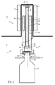
- Fig. 1 shows a side view of a capper 1 according to the invention in a sectional view.
- a bottling plant downstream of a filling machine, a plurality of the closers 1 shown can be arranged at evenly spaced intervals on the circumference of a closing carousel.
- An electric motor 5 with a stator 7 and a rotor 6 can be seen, wherein an element for clean room separation 9 is formed between the two.
- the closure head 4 connected to the rotor 6 acts within a clean room 3 in order to close containers (not shown here).
- an ejection bar 8 which serves to eject container closures 11 if they have not been screwed onto a container.
- a magnetic field is generated by the clean room separation element 9, which acts on the magnets 6b of the rotor 6.
- the stator 7 comprises in the direction of the axis A and in the circumferential direction in each case a plurality of magnetic coils. This makes it possible to generate such a magnetic field that the rotor 6 can be rotated both about the axis A and height-adjustable along the axis A (corresponding to the arrows).
- the element for clean room separation 9 so the clean room 3 is hermetically separated from the environment 15.
- the capping head 4 is integrally connected to the rotor 6.
- On the central axis A of the rotor 6 and the capper 4 is a cylindrical through hole with the cylindrical inner surfaces 4a, 6a. These serve as plain bearings with respect to the Auswerfstange 8, which in turn has a cylindrical outer surface 8c.
- the Cylindrical outer surface 8c and the cylindrical inner surfaces 4a, 6a are designed to each other as a clearance fit.
- the Auswerfstange 8 At the first end 8a (top) of the Auswerfstange 8 is a screw thread. About the thread the Auswerfstange 8 is screwed into the receptacle 12, which in turn is firmly connected to the clean room separation element 9. Thus, the Auswerfstange 8 is stably connected to the element for clean room separation 9 and provides a precise guidance of the rotor 6 and the Verschmonykopfs 4 for carrying out the lifting / rotating movement. Furthermore, the Auswerfstange 8 can be unscrewed, for example, for maintenance on the rotor 6 from the receptacle 12 and thus rotor 6 and 8 Auswerfstange be removed.
- the securing element 10 is designed as a mechanical stop for the closing head 4.
- the securing element 10 has a conical surface 10a and the capper 4 a corresponding conical counter surface 4b.
- the securing element 10 limits the movement of the capper 4 downwards (more precisely in the description of the figures for Fig. 4 described).
- the diameter of the cylindrical inner surface 4c is made larger than that of the securing element 10.
- the securing element 10 has a lower end face 10 b for ejecting the container closures 11 (more precisely in the description of the figures for Fig. 3 described).
- the securing element 10 can also be unscrewed via a thread (not shown here) from the lower end 8b of the Auswerfstange 8 to remove the capping head 4 and the rotor 6 from the capper 1 during service.
- the capper 4 receives a container closure 11 from the pick-and-place station 13.
- the closures 11 are received in a receiving area 4d by means of gripping lips 4e.
- the ejection rod 8 does not protrude into the receiving area 4d.
- Fig. 2 shows a side view of the capper 1 of the invention from the Fig. 1 when closing a container 2 with a container closure 11 in a sectional view. It can be seen that the container 2 is received on the neck 2a and the collar 2b in a receiving element 14. Further, the container 2 can not rotate about the axis A, or lower down. The capper 1 closes the container 2 with a container closure 11 (screw cap) via a lifting / rotating movement.
- a container closure 11 screw cap
- the stator 7 generates such a magnetic field that rotates the rotor 6 of the electric motor 5 in a spiral movement about the axis A both to the right and lower. This spiral movement corresponds to the pitch of the thread of the container closure 11.
- the inventive design of the capper 1, this can perform the desired lifting / rotating movement without a complex control curve and simultaneously there is a hermetic separation of the clean room 3 with respect to the environment 15 with the element for clean room separation 9, so that no contamination when closing in the container. 2 get in.
- Fig. 3 shows a side view of the capper 1 according to the invention when ejecting a container closure 11 in a sectional view. If now when closing a container 2 in the in Fig. 2 is missing, remains the closure 11 in the capping 4. In order to avoid a collision, this is ejected before receiving another container closure 11.
- the capping head 4 is raised above the rotor 6 to such an extent that the ejection rod 8 protrudes into the receiving area 4d so far that the closure 11 is released and falls downwardly out of the gripping lips 4e in the capping head 4.
- the end face 10b of the securing element 10 which is attached to the lower end 8b of the ejection bar 8, contacts the closure 11 and pushes it out downwards. Subsequently, the capping head 4 is again free to receive a further container closure 11.
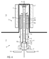
- Fig. 4 shows a side view of the capper 1 of the invention from the Fig. 1 in a lower stop position P. It can be seen how after a power failure, the closing head 4 and the rotor 6 is no longer held by the magnetic forces of the stator 7 and has fallen down so.
- the conical surface 10a of the securing element 10 has an outer diameter D, which is greater than the diameter d of the cylindrical inner surfaces 4a, 6a of the capper 4 and the rotor 6. This prevents the capper 4 or the rotor 6 continue to fall over the lower stop position P down from the capper 1.
- the lower stop position P is chosen so that the capper 4 at its lower end not with the receptacle 14th collided. This avoids damage to the capping head 4 and / or the receptacle 14 in the event of a power failure.
- FIG. 5a, 5b is a partial side view of the capping head 4 of a capper according to the invention 1 shown in a sectional view, wherein the securing element 10 between a securing position S and a release position F back and forth.
- the securing element 10 is in this case attached laterally to the second, lower end 8b of the ejection rod 8 and formed triangular. Within the second end 8b of the Auswerfstange 8 is thereby a spring (not shown here), in the Fig. 5a exerts a force to the right or outward on the securing element 10. In the securing position S, the securing element 10 has an upper, planar surface 10a, which forms the mechanical stop for the flat mating surface 4b in the closing head 4. When the closing head 4 falls down, the vertical movement is limited by this mechanical stop downwards.
- the user can now the fuse element 10 in the Fig. 5a push so far into the Auswerfstange 8 that it then forms with the Auswerfstange 8 such a small cross-section that it passes through the cylindrical inner surface 4 a of the Verschebenkopfs 4 passes. Consequently, now the capping head 4 in the Fig. 5b Released in a release position so that it can be removed by the user down from the capper 1.
Landscapes
- Engineering & Computer Science (AREA)
- Mechanical Engineering (AREA)
- Power Engineering (AREA)
- Sealing Of Jars (AREA)
Claims (12)
- Dispositif de fermeture (1) pour récipients ou contenants (2), notamment des bouteilles, comprenant une tête de fermeture (4) agissant dans une chambre stérile (3) ou en conditions de salle blanche, et comprenant un moteur électrique (5) comportant au moins un rotor (6) et un stator (7), dispositif
dans lequel la tête de fermeture (4) est reliée au rotor (6), et dans lequel entre le rotor (6) et le stator (7) est formé un élément d'isolement de chambre stérile (9), caractérisé
en ce qu'il est prévu une tige d'éjection (8) pour éjecter des bouchons de fermeture de contenant (11) de la tête de fermeture (4) et comportant une première et une deuxième extrémité (8a, 8b), ladite tige d'éjection étant, à sa première extrémité (8a), reliée à l'élément d'isolement de chambre stérile (9), et étant configurée en tant que guidage du rotor (6) et/ou de la tête de fermeture (4). - Dispositif de fermeture (1) selon la revendication 1, dans lequel le rotor (6) et la tête de fermeture (4) sont agencés autour de la tige d'éjection (8) et concentriquement à son axe longitudinal (A).
- Dispositif de fermeture (1) selon l'une au moins des revendications précédentes, dans lequel une surface extérieure cylindrique (8c) de la tige d'éjection (8) et une surface intérieure cylindrique (6a) du rotor (6) et/ou une surface intérieure cylindrique (4a) de la tête de fermeture (4) sont réalisées en tant que palier lisse.
- Dispositif de fermeture (1) selon l'une au moins des revendications précédentes, dans lequel un élément d'arrêt de sécurité (10) est relié de manière fixe ou amovible à la tige d'éjection (8), et est configuré pour former une butée mécanique d'une position de butée inférieure (P) de la tête de fermeture (4).
- Dispositif de fermeture (1) selon la revendication 4, dans lequel l'élément d'arrêt de sécurité (10) comporte, pour former la butée mécanique, une surface (10a) plane, conique et/ou sphérique, qui présente notamment un diamètre extérieur (D) plus grand que celui de la tige d'éjection (8), et dans lequel la tête de fermeture (4) ou le rotor (6) comporte une surface conjuguée (4b) correspondante.
- Dispositif de fermeture (1) selon la revendication 4 ou la revendication 5, dans lequel l'élément d'arrêt de sécurité (10) est relié à la deuxième extrémité (8b) de la tige d'éjection (8), notamment dans lequel une surface frontale (10b) de l'élément d'arrêt de sécurité (10) est configurée pour l'éjection de bouchons de fermeture de contenant (11).
- Dispositif de fermeture (1) selon l'une au moins des revendications 4 - 6, dans lequel l'élément d'arrêt de sécurité (10) forme la butée mécanique dans une position d'arrêt de sécurité (S) et autorise, dans une position de dégagement (F), une extraction de la tête de fermeture (4) du dispositif de fermeture (1), l'élément d'arrêt de sécurité (10) étant conçu de manière à pouvoir être mobile de manière alternée entre la position d'arrêt de sécurité (S) et la position de dégagement (F).
- Installation de conditionnement par remplissage comprenant un dispositif de fermeture (1) selon l'une au moins des revendications 1 - 7.
- Procédé pour fermer des récipients ou contenants (2), notamment des bouteilles, à l'aide de bouchons de fermeture (11), comprenant un dispositif de fermeture selon l'une des revendications 1 - 8, d'après lequel le stator (7) du moteur électrique (5) produit un champ magnétique, qui agit à travers l'élément d'isolement de chambre stérile (9) pour assurer le mouvement du rotor (6), et le rotor (6) entraîne la tête de fermeture (4), les bouchons de fermeture de contenant (11) pouvant être éjectés de la tête de fermeture (4) à l'aide de la tige d'éjection (8), et la tige d'éjection (8) guidant le rotor (6) et/ou la tête de fermeture (4).
- Procédé selon la revendication 9, d'après lequel en cas d'une coupure de courant du moteur électrique (5), un élément d'arrêt de sécurité (10) assure un arrêt de sécurité du rotor (6) et/ou de la tête de fermeture (4) à l'encontre d'un mouvement de déplacement au-delà d'une position de butée inférieure (P).
- Procédé selon la revendication 9 ou la revendication 10, d'après lequel lors d'un service en mode d'installation, d'entretien ou de réparation, on sépare l'élément d'arrêt de sécurité (10) de la tige d'éjection (8), en vue de retirer ou déposer le rotor (6) et la tête de fermeture (4).
- Procédé selon la revendication 9 ou la revendication 10, d'après lequel lors d'un service en mode d'installation, d'entretien ou de réparation, on sépare la tige d'éjection (8) avec l'élément d'arrêt de sécurité (10) de l'élément d'isolement de chambre stérile (9), en vue de retirer ou déposer le rotor (6) et la tête de fermeture (4).
Applications Claiming Priority (1)
| Application Number | Priority Date | Filing Date | Title |
|---|---|---|---|
| DE102012219756.7A DE102012219756A1 (de) | 2012-10-29 | 2012-10-29 | Verschließer für Behälter |
Publications (2)
| Publication Number | Publication Date |
|---|---|
| EP2724979A1 EP2724979A1 (fr) | 2014-04-30 |
| EP2724979B1 true EP2724979B1 (fr) | 2016-06-08 |
Family
ID=49382259
Family Applications (1)
| Application Number | Title | Priority Date | Filing Date |
|---|---|---|---|
| EP13188330.8A Active EP2724979B1 (fr) | 2012-10-29 | 2013-10-11 | Machine de fermeture pour récipients |
Country Status (3)
| Country | Link |
|---|---|
| EP (1) | EP2724979B1 (fr) |
| CN (1) | CN103787249B (fr) |
| DE (1) | DE102012219756A1 (fr) |
Families Citing this family (2)
| Publication number | Priority date | Publication date | Assignee | Title |
|---|---|---|---|---|
| DE102020114904A1 (de) | 2020-06-04 | 2021-12-09 | Krones Aktiengesellschaft | Vorrichtung zum Verschließen von Behältern mit magnetischem Verschlussauswurf |
| DE102024102536A1 (de) * | 2024-01-30 | 2025-07-31 | Krones Aktiengesellschaft | Vorrichtung zum Aufbringen eines Behälterverschlusses auf einen Behälter und Verschließer |
Family Cites Families (9)
| Publication number | Priority date | Publication date | Assignee | Title |
|---|---|---|---|---|
| DE1044752B (de) * | 1951-06-29 | 1958-11-27 | Heinrich Tappolet | Vorrichtung zur Herstellung einer Kappe zum Verschliessen von Flaschen |
| US3031822A (en) * | 1961-02-21 | 1962-05-01 | Cons Packaging Machinery Corp | Chuck for capping machines |
| IT1318836B1 (it) * | 2000-09-08 | 2003-09-10 | Marco Cipriani | Dispositivo ad accoppiamento magnetico per la trasmissione e lamisurazione di coppia. |
| DE10322465A1 (de) * | 2003-05-16 | 2004-12-02 | Ksb Aktiengesellschaft | Trennhülse |
| DE102005031319B4 (de) * | 2005-07-05 | 2017-02-16 | Krones Aktiengesellschaft | Vorrichtung zur Höhenverstellung eines Rückgasrohrs einer Füllmaschine |
| DE102006039090A1 (de) * | 2006-08-19 | 2008-02-21 | Khs Ag | Antrieb für Rotationsmaschinen |
| DE102007057857A1 (de) * | 2007-11-29 | 2009-06-04 | Khs Ag | Vorrichtung zum Verschließen von Behältern |
| DE102009009822A1 (de) | 2009-02-20 | 2010-08-26 | Krones Ag | Vorrichtung zum Verschließen von Behältnissen mit berührungsloser Drehmomentenerzeugung |
| DE102009017109A1 (de) | 2009-04-15 | 2010-10-28 | Khs Gmbh | Verschließer für Schraubkappen bzw. -verschlüsse |
-
2012
- 2012-10-29 DE DE102012219756.7A patent/DE102012219756A1/de not_active Withdrawn
-
2013
- 2013-10-11 EP EP13188330.8A patent/EP2724979B1/fr active Active
- 2013-10-29 CN CN201310521457.2A patent/CN103787249B/zh active Active
Non-Patent Citations (1)
| Title |
|---|
| None * |
Also Published As
| Publication number | Publication date |
|---|---|
| DE102012219756A1 (de) | 2014-04-30 |
| CN103787249B (zh) | 2016-01-27 |
| EP2724979A1 (fr) | 2014-04-30 |
| CN103787249A (zh) | 2014-05-14 |
Similar Documents
| Publication | Publication Date | Title |
|---|---|---|
| EP2724976B1 (fr) | Machine de fermeture pour récipients | |
| EP2674390B1 (fr) | Machine de fermeture de récipients | |
| EP2300352B1 (fr) | Machine de fermeture | |
| EP2221272B1 (fr) | Dispositif de fermeture de récipients doté d'une production à couple sans contact | |
| EP2958848B1 (fr) | Dispositif et machine pour la fermeture des recipients | |
| EP2588147B1 (fr) | Dispositif destiné à stériliser des éléments de fermeture pour des récipients | |
| EP2724977B1 (fr) | Machine de fermeture pour récipients | |
| WO2014198824A1 (fr) | Dispositif de transport de récipients | |
| WO2010118806A2 (fr) | Dispositif de fermeture pour capsules ou fermetures filetées | |
| EP3137410B1 (fr) | Machine et procédé de traitement de récipients | |
| EP2724978B1 (fr) | Machine de fermeture pour récipients | |
| EP2730533B1 (fr) | Dispositif d'application d'une fermeture sur un récipient | |
| EP2724979B1 (fr) | Machine de fermeture pour récipients | |
| EP2576417B1 (fr) | Dispositif aimanté d'éjection de capsules dans un dispositif de fermeture | |
| EP2735429B1 (fr) | Dispositif de traitement de récipient doté d'un dispositif d'étirage | |
| EP3331812B1 (fr) | Procédé de nettoyage et/ou de désinfection d'éléments de fermeture et machine de fermeture | |
| EP2657179B1 (fr) | Dispositif destiné à fermer des bouteilles en plastique | |
| EP2736835B1 (fr) | Dispositif de fermeture de récipients | |
| EP2285725B1 (fr) | Dispositif pour fermer des récipients avec un bouchon à visser | |
| EP2789574A1 (fr) | Dispositif et procédé de traitement de bouchons de récipients et machine de remplissage aseptique | |
| DE102014005765A1 (de) | Verfahren zum Aufschrauben eines Schraubverschlusses auf einen Behälter und Aufschraub- bzw. Abschraubvorrichtung zur Ausführung dieses Vorgangs | |
| EP3828128A1 (fr) | Dispositif de fermeture pour récipient avec un bouchon à vis | |
| DE202019106761U1 (de) | Verschließvorrichtung |
Legal Events
| Date | Code | Title | Description |
|---|---|---|---|
| PUAI | Public reference made under article 153(3) epc to a published international application that has entered the european phase |
Free format text: ORIGINAL CODE: 0009012 |
|
| 17P | Request for examination filed |
Effective date: 20131011 |
|
| AK | Designated contracting states |
Kind code of ref document: A1 Designated state(s): AL AT BE BG CH CY CZ DE DK EE ES FI FR GB GR HR HU IE IS IT LI LT LU LV MC MK MT NL NO PL PT RO RS SE SI SK SM TR |
|
| AX | Request for extension of the european patent |
Extension state: BA ME |
|
| 17P | Request for examination filed |
Effective date: 20141030 |
|
| RBV | Designated contracting states (corrected) |
Designated state(s): AL AT BE BG CH CY CZ DE DK EE ES FI FR GB GR HR HU IE IS IT LI LT LU LV MC MK MT NL NO PL PT RO RS SE SI SK SM TR |
|
| GRAP | Despatch of communication of intention to grant a patent |
Free format text: ORIGINAL CODE: EPIDOSNIGR1 |
|
| RIC1 | Information provided on ipc code assigned before grant |
Ipc: H02K 21/12 20060101ALI20160208BHEP Ipc: H02K 5/128 20060101ALI20160208BHEP Ipc: B67B 3/20 20060101AFI20160208BHEP |
|
| INTG | Intention to grant announced |
Effective date: 20160224 |
|
| GRAS | Grant fee paid |
Free format text: ORIGINAL CODE: EPIDOSNIGR3 |
|
| GRAA | (expected) grant |
Free format text: ORIGINAL CODE: 0009210 |
|
| AK | Designated contracting states |
Kind code of ref document: B1 Designated state(s): AL AT BE BG CH CY CZ DE DK EE ES FI FR GB GR HR HU IE IS IT LI LT LU LV MC MK MT NL NO PL PT RO RS SE SI SK SM TR |
|
| REG | Reference to a national code |
Ref country code: GB Ref legal event code: FG4D Free format text: NOT ENGLISH |
|
| REG | Reference to a national code |
Ref country code: CH Ref legal event code: EP |
|
| REG | Reference to a national code |
Ref country code: IE Ref legal event code: FG4D Free format text: LANGUAGE OF EP DOCUMENT: GERMAN |
|
| REG | Reference to a national code |
Ref country code: AT Ref legal event code: REF Ref document number: 805085 Country of ref document: AT Kind code of ref document: T Effective date: 20160715 |
|
| REG | Reference to a national code |
Ref country code: DE Ref legal event code: R096 Ref document number: 502013003319 Country of ref document: DE |
|
| REG | Reference to a national code |
Ref country code: FR Ref legal event code: PLFP Year of fee payment: 4 |
|
| REG | Reference to a national code |
Ref country code: LT Ref legal event code: MG4D |
|
| REG | Reference to a national code |
Ref country code: NL Ref legal event code: MP Effective date: 20160608 |
|
| PG25 | Lapsed in a contracting state [announced via postgrant information from national office to epo] |
Ref country code: NO Free format text: LAPSE BECAUSE OF FAILURE TO SUBMIT A TRANSLATION OF THE DESCRIPTION OR TO PAY THE FEE WITHIN THE PRESCRIBED TIME-LIMIT Effective date: 20160908 Ref country code: LT Free format text: LAPSE BECAUSE OF FAILURE TO SUBMIT A TRANSLATION OF THE DESCRIPTION OR TO PAY THE FEE WITHIN THE PRESCRIBED TIME-LIMIT Effective date: 20160608 Ref country code: FI Free format text: LAPSE BECAUSE OF FAILURE TO SUBMIT A TRANSLATION OF THE DESCRIPTION OR TO PAY THE FEE WITHIN THE PRESCRIBED TIME-LIMIT Effective date: 20160608 |
|
| PG25 | Lapsed in a contracting state [announced via postgrant information from national office to epo] |
Ref country code: LV Free format text: LAPSE BECAUSE OF FAILURE TO SUBMIT A TRANSLATION OF THE DESCRIPTION OR TO PAY THE FEE WITHIN THE PRESCRIBED TIME-LIMIT Effective date: 20160608 Ref country code: HR Free format text: LAPSE BECAUSE OF FAILURE TO SUBMIT A TRANSLATION OF THE DESCRIPTION OR TO PAY THE FEE WITHIN THE PRESCRIBED TIME-LIMIT Effective date: 20160608 Ref country code: GR Free format text: LAPSE BECAUSE OF FAILURE TO SUBMIT A TRANSLATION OF THE DESCRIPTION OR TO PAY THE FEE WITHIN THE PRESCRIBED TIME-LIMIT Effective date: 20160909 Ref country code: RS Free format text: LAPSE BECAUSE OF FAILURE TO SUBMIT A TRANSLATION OF THE DESCRIPTION OR TO PAY THE FEE WITHIN THE PRESCRIBED TIME-LIMIT Effective date: 20160608 Ref country code: NL Free format text: LAPSE BECAUSE OF FAILURE TO SUBMIT A TRANSLATION OF THE DESCRIPTION OR TO PAY THE FEE WITHIN THE PRESCRIBED TIME-LIMIT Effective date: 20160608 Ref country code: SE Free format text: LAPSE BECAUSE OF FAILURE TO SUBMIT A TRANSLATION OF THE DESCRIPTION OR TO PAY THE FEE WITHIN THE PRESCRIBED TIME-LIMIT Effective date: 20160608 Ref country code: ES Free format text: LAPSE BECAUSE OF FAILURE TO SUBMIT A TRANSLATION OF THE DESCRIPTION OR TO PAY THE FEE WITHIN THE PRESCRIBED TIME-LIMIT Effective date: 20160608 |
|
| PG25 | Lapsed in a contracting state [announced via postgrant information from national office to epo] |
Ref country code: EE Free format text: LAPSE BECAUSE OF FAILURE TO SUBMIT A TRANSLATION OF THE DESCRIPTION OR TO PAY THE FEE WITHIN THE PRESCRIBED TIME-LIMIT Effective date: 20160608 Ref country code: RO Free format text: LAPSE BECAUSE OF FAILURE TO SUBMIT A TRANSLATION OF THE DESCRIPTION OR TO PAY THE FEE WITHIN THE PRESCRIBED TIME-LIMIT Effective date: 20160608 Ref country code: IS Free format text: LAPSE BECAUSE OF FAILURE TO SUBMIT A TRANSLATION OF THE DESCRIPTION OR TO PAY THE FEE WITHIN THE PRESCRIBED TIME-LIMIT Effective date: 20161008 Ref country code: CZ Free format text: LAPSE BECAUSE OF FAILURE TO SUBMIT A TRANSLATION OF THE DESCRIPTION OR TO PAY THE FEE WITHIN THE PRESCRIBED TIME-LIMIT Effective date: 20160608 Ref country code: SK Free format text: LAPSE BECAUSE OF FAILURE TO SUBMIT A TRANSLATION OF THE DESCRIPTION OR TO PAY THE FEE WITHIN THE PRESCRIBED TIME-LIMIT Effective date: 20160608 |
|
| PG25 | Lapsed in a contracting state [announced via postgrant information from national office to epo] |
Ref country code: PT Free format text: LAPSE BECAUSE OF FAILURE TO SUBMIT A TRANSLATION OF THE DESCRIPTION OR TO PAY THE FEE WITHIN THE PRESCRIBED TIME-LIMIT Effective date: 20161010 Ref country code: BE Free format text: LAPSE BECAUSE OF NON-PAYMENT OF DUE FEES Effective date: 20161031 Ref country code: SM Free format text: LAPSE BECAUSE OF FAILURE TO SUBMIT A TRANSLATION OF THE DESCRIPTION OR TO PAY THE FEE WITHIN THE PRESCRIBED TIME-LIMIT Effective date: 20160608 Ref country code: PL Free format text: LAPSE BECAUSE OF FAILURE TO SUBMIT A TRANSLATION OF THE DESCRIPTION OR TO PAY THE FEE WITHIN THE PRESCRIBED TIME-LIMIT Effective date: 20160608 |
|
| REG | Reference to a national code |
Ref country code: DE Ref legal event code: R097 Ref document number: 502013003319 Country of ref document: DE |
|
| PLBE | No opposition filed within time limit |
Free format text: ORIGINAL CODE: 0009261 |
|
| STAA | Information on the status of an ep patent application or granted ep patent |
Free format text: STATUS: NO OPPOSITION FILED WITHIN TIME LIMIT |
|
| 26N | No opposition filed |
Effective date: 20170309 |
|
| PG25 | Lapsed in a contracting state [announced via postgrant information from national office to epo] |
Ref country code: DK Free format text: LAPSE BECAUSE OF FAILURE TO SUBMIT A TRANSLATION OF THE DESCRIPTION OR TO PAY THE FEE WITHIN THE PRESCRIBED TIME-LIMIT Effective date: 20160608 Ref country code: SI Free format text: LAPSE BECAUSE OF FAILURE TO SUBMIT A TRANSLATION OF THE DESCRIPTION OR TO PAY THE FEE WITHIN THE PRESCRIBED TIME-LIMIT Effective date: 20160608 |
|
| REG | Reference to a national code |
Ref country code: CH Ref legal event code: PL |
|
| REG | Reference to a national code |
Ref country code: IE Ref legal event code: MM4A |
|
| PG25 | Lapsed in a contracting state [announced via postgrant information from national office to epo] |
Ref country code: LI Free format text: LAPSE BECAUSE OF NON-PAYMENT OF DUE FEES Effective date: 20161031 Ref country code: CH Free format text: LAPSE BECAUSE OF NON-PAYMENT OF DUE FEES Effective date: 20161031 |
|
| PG25 | Lapsed in a contracting state [announced via postgrant information from national office to epo] |
Ref country code: LU Free format text: LAPSE BECAUSE OF NON-PAYMENT OF DUE FEES Effective date: 20161011 |
|
| REG | Reference to a national code |
Ref country code: FR Ref legal event code: PLFP Year of fee payment: 5 |
|
| PG25 | Lapsed in a contracting state [announced via postgrant information from national office to epo] |
Ref country code: IE Free format text: LAPSE BECAUSE OF NON-PAYMENT OF DUE FEES Effective date: 20161011 |
|
| REG | Reference to a national code |
Ref country code: BE Ref legal event code: MM Effective date: 20161031 |
|
| PG25 | Lapsed in a contracting state [announced via postgrant information from national office to epo] |
Ref country code: HU Free format text: LAPSE BECAUSE OF FAILURE TO SUBMIT A TRANSLATION OF THE DESCRIPTION OR TO PAY THE FEE WITHIN THE PRESCRIBED TIME-LIMIT; INVALID AB INITIO Effective date: 20131011 Ref country code: CY Free format text: LAPSE BECAUSE OF FAILURE TO SUBMIT A TRANSLATION OF THE DESCRIPTION OR TO PAY THE FEE WITHIN THE PRESCRIBED TIME-LIMIT Effective date: 20160608 |
|
| GBPC | Gb: european patent ceased through non-payment of renewal fee |
Effective date: 20171011 |
|
| PG25 | Lapsed in a contracting state [announced via postgrant information from national office to epo] |
Ref country code: MK Free format text: LAPSE BECAUSE OF FAILURE TO SUBMIT A TRANSLATION OF THE DESCRIPTION OR TO PAY THE FEE WITHIN THE PRESCRIBED TIME-LIMIT Effective date: 20160608 Ref country code: MC Free format text: LAPSE BECAUSE OF FAILURE TO SUBMIT A TRANSLATION OF THE DESCRIPTION OR TO PAY THE FEE WITHIN THE PRESCRIBED TIME-LIMIT Effective date: 20160608 Ref country code: MT Free format text: LAPSE BECAUSE OF FAILURE TO SUBMIT A TRANSLATION OF THE DESCRIPTION OR TO PAY THE FEE WITHIN THE PRESCRIBED TIME-LIMIT Effective date: 20160608 |
|
| PG25 | Lapsed in a contracting state [announced via postgrant information from national office to epo] |
Ref country code: GB Free format text: LAPSE BECAUSE OF NON-PAYMENT OF DUE FEES Effective date: 20171011 Ref country code: BG Free format text: LAPSE BECAUSE OF FAILURE TO SUBMIT A TRANSLATION OF THE DESCRIPTION OR TO PAY THE FEE WITHIN THE PRESCRIBED TIME-LIMIT Effective date: 20160608 |
|
| REG | Reference to a national code |
Ref country code: FR Ref legal event code: PLFP Year of fee payment: 6 |
|
| PG25 | Lapsed in a contracting state [announced via postgrant information from national office to epo] |
Ref country code: AL Free format text: LAPSE BECAUSE OF FAILURE TO SUBMIT A TRANSLATION OF THE DESCRIPTION OR TO PAY THE FEE WITHIN THE PRESCRIBED TIME-LIMIT Effective date: 20160608 Ref country code: TR Free format text: LAPSE BECAUSE OF FAILURE TO SUBMIT A TRANSLATION OF THE DESCRIPTION OR TO PAY THE FEE WITHIN THE PRESCRIBED TIME-LIMIT Effective date: 20160608 |
|
| REG | Reference to a national code |
Ref country code: AT Ref legal event code: MM01 Ref document number: 805085 Country of ref document: AT Kind code of ref document: T Effective date: 20181011 |
|
| PG25 | Lapsed in a contracting state [announced via postgrant information from national office to epo] |
Ref country code: AT Free format text: LAPSE BECAUSE OF NON-PAYMENT OF DUE FEES Effective date: 20181011 |
|
| P01 | Opt-out of the competence of the unified patent court (upc) registered |
Effective date: 20230523 |
|
| PGFP | Annual fee paid to national office [announced via postgrant information from national office to epo] |
Ref country code: IT Payment date: 20250922 Year of fee payment: 13 |
|
| PGFP | Annual fee paid to national office [announced via postgrant information from national office to epo] |
Ref country code: FR Payment date: 20250908 Year of fee payment: 13 |
|
| PGFP | Annual fee paid to national office [announced via postgrant information from national office to epo] |
Ref country code: DE Payment date: 20250902 Year of fee payment: 13 |