EP2576996B1 - Abgasturbolader mit gleitlager zur verminderung von fluidwirbeln - Google Patents
Abgasturbolader mit gleitlager zur verminderung von fluidwirbeln Download PDFInfo
- Publication number
- EP2576996B1 EP2576996B1 EP11721317.3A EP11721317A EP2576996B1 EP 2576996 B1 EP2576996 B1 EP 2576996B1 EP 11721317 A EP11721317 A EP 11721317A EP 2576996 B1 EP2576996 B1 EP 2576996B1
- Authority
- EP
- European Patent Office
- Prior art keywords
- rotor shaft
- groove
- transverse
- inner segment
- gas turbocharger
- Prior art date
- Legal status (The legal status is an assumption and is not a legal conclusion. Google has not performed a legal analysis and makes no representation as to the accuracy of the status listed.)
- Not-in-force
Links
- 239000012530 fluid Substances 0.000 title claims description 85
- 230000003247 decreasing effect Effects 0.000 claims description 5
- 230000007423 decrease Effects 0.000 claims 1
- 230000000694 effects Effects 0.000 description 4
- 230000001419 dependent effect Effects 0.000 description 3
- 238000005086 pumping Methods 0.000 description 3
- 238000007667 floating Methods 0.000 description 2
- 230000010355 oscillation Effects 0.000 description 2
- 238000005452 bending Methods 0.000 description 1
- 230000015572 biosynthetic process Effects 0.000 description 1
- 238000010276 construction Methods 0.000 description 1
- 230000001066 destructive effect Effects 0.000 description 1
- 238000002955 isolation Methods 0.000 description 1
- 238000011017 operating method Methods 0.000 description 1
Images


Classifications
-
- F—MECHANICAL ENGINEERING; LIGHTING; HEATING; WEAPONS; BLASTING
- F01—MACHINES OR ENGINES IN GENERAL; ENGINE PLANTS IN GENERAL; STEAM ENGINES
- F01D—NON-POSITIVE DISPLACEMENT MACHINES OR ENGINES, e.g. STEAM TURBINES
- F01D25/00—Component parts, details, or accessories, not provided for in, or of interest apart from, other groups
- F01D25/16—Arrangement of bearings; Supporting or mounting bearings in casings
- F01D25/166—Sliding contact bearing
-
- F—MECHANICAL ENGINEERING; LIGHTING; HEATING; WEAPONS; BLASTING
- F01—MACHINES OR ENGINES IN GENERAL; ENGINE PLANTS IN GENERAL; STEAM ENGINES
- F01D—NON-POSITIVE DISPLACEMENT MACHINES OR ENGINES, e.g. STEAM TURBINES
- F01D25/00—Component parts, details, or accessories, not provided for in, or of interest apart from, other groups
- F01D25/18—Lubricating arrangements
-
- F—MECHANICAL ENGINEERING; LIGHTING; HEATING; WEAPONS; BLASTING
- F16—ENGINEERING ELEMENTS AND UNITS; GENERAL MEASURES FOR PRODUCING AND MAINTAINING EFFECTIVE FUNCTIONING OF MACHINES OR INSTALLATIONS; THERMAL INSULATION IN GENERAL
- F16C—SHAFTS; FLEXIBLE SHAFTS; ELEMENTS OR CRANKSHAFT MECHANISMS; ROTARY BODIES OTHER THAN GEARING ELEMENTS; BEARINGS
- F16C17/00—Sliding-contact bearings for exclusively rotary movement
- F16C17/02—Sliding-contact bearings for exclusively rotary movement for radial load only
- F16C17/026—Sliding-contact bearings for exclusively rotary movement for radial load only with helical grooves in the bearing surface to generate hydrodynamic pressure, e.g. herringbone grooves
-
- F—MECHANICAL ENGINEERING; LIGHTING; HEATING; WEAPONS; BLASTING
- F16—ENGINEERING ELEMENTS AND UNITS; GENERAL MEASURES FOR PRODUCING AND MAINTAINING EFFECTIVE FUNCTIONING OF MACHINES OR INSTALLATIONS; THERMAL INSULATION IN GENERAL
- F16C—SHAFTS; FLEXIBLE SHAFTS; ELEMENTS OR CRANKSHAFT MECHANISMS; ROTARY BODIES OTHER THAN GEARING ELEMENTS; BEARINGS
- F16C17/00—Sliding-contact bearings for exclusively rotary movement
- F16C17/12—Sliding-contact bearings for exclusively rotary movement characterised by features not related to the direction of the load
- F16C17/18—Sliding-contact bearings for exclusively rotary movement characterised by features not related to the direction of the load with floating brasses or brushing, rotatable at a reduced speed
-
- F—MECHANICAL ENGINEERING; LIGHTING; HEATING; WEAPONS; BLASTING
- F16—ENGINEERING ELEMENTS AND UNITS; GENERAL MEASURES FOR PRODUCING AND MAINTAINING EFFECTIVE FUNCTIONING OF MACHINES OR INSTALLATIONS; THERMAL INSULATION IN GENERAL
- F16C—SHAFTS; FLEXIBLE SHAFTS; ELEMENTS OR CRANKSHAFT MECHANISMS; ROTARY BODIES OTHER THAN GEARING ELEMENTS; BEARINGS
- F16C33/00—Parts of bearings; Special methods for making bearings or parts thereof
- F16C33/02—Parts of sliding-contact bearings
- F16C33/04—Brasses; Bushes; Linings
- F16C33/06—Sliding surface mainly made of metal
- F16C33/10—Construction relative to lubrication
- F16C33/1025—Construction relative to lubrication with liquid, e.g. oil, as lubricant
- F16C33/106—Details of distribution or circulation inside the bearings, e.g. details of the bearing surfaces to affect flow or pressure of the liquid
- F16C33/107—Grooves for generating pressure
-
- F—MECHANICAL ENGINEERING; LIGHTING; HEATING; WEAPONS; BLASTING
- F05—INDEXING SCHEMES RELATING TO ENGINES OR PUMPS IN VARIOUS SUBCLASSES OF CLASSES F01-F04
- F05D—INDEXING SCHEME FOR ASPECTS RELATING TO NON-POSITIVE-DISPLACEMENT MACHINES OR ENGINES, GAS-TURBINES OR JET-PROPULSION PLANTS
- F05D2220/00—Application
- F05D2220/40—Application in turbochargers
-
- F—MECHANICAL ENGINEERING; LIGHTING; HEATING; WEAPONS; BLASTING
- F16—ENGINEERING ELEMENTS AND UNITS; GENERAL MEASURES FOR PRODUCING AND MAINTAINING EFFECTIVE FUNCTIONING OF MACHINES OR INSTALLATIONS; THERMAL INSULATION IN GENERAL
- F16C—SHAFTS; FLEXIBLE SHAFTS; ELEMENTS OR CRANKSHAFT MECHANISMS; ROTARY BODIES OTHER THAN GEARING ELEMENTS; BEARINGS
- F16C2360/00—Engines or pumps
- F16C2360/23—Gas turbine engines
- F16C2360/24—Turbochargers
Definitions
- the present invention relates to an exhaust gas turbocharger with a rotor shaft, having the features of the preamble of claim 1.
- an exhaust gas turbocharger which has a plurality of axially extending grooves in a radial bearing which rotatably supports a shaft of the exhaust gas turbocharger.
- the grooves in the profile may have a V or U shape.
- the axially extending grooves advantageously enable a further development of the rotor dynamics of such an exhaust gas turbocharger, since an exhaust gas turbocharger with such axially extending grooves in the radial bearings has an increased resistance to a known as self-excited subsynchronous vibration movement of the rotor shaft. This is achieved by a reduction of fluid vortices in the fluid film arranged between the radial bearing and the rotor shaft, in particular in the low load range.
- fluid whirl also includes the technical term "oil whirl".
- the occurrence of such fluid vortices is known when using slide bearings in charging devices and is caused due to the rotating rotor shaft around the bearing center, wherein in the arranged between the radial bearing and the rotor shaft fluid film inner and outer fluid vortices can be distinguished. Fluid vortices occur in particular even at high-speed rotation and cause, especially at higher speeds, a tumbling motion of the rotor or the rotor shaft in cylindrical and conical vibration modes, which is also known as "self-excited subsynchronous oscillation".
- the internal fluid vortex induces due to the flow of the inner fluid film, a constant tone whose dependent of the respective fluid temperature frequency is of the order of a half-frequency of the rotor speed.
- the induced by the fluid vortex constant tone can have a broadband frequency of 600 to 900 Hz, which occur at corresponding engine speeds of 1500 to 3500 U / min.
- the self-excited oscillation occurring by the fluid vortex which can cause the rotor deflection to an unstable state, can lead to bearing damage under unfavorable operating conditions.
- Such a destructive vibration can occur when the frequency of the constant tone of the fluid vortex is equal to the critical frequency of the first order of bending of the rotor-bearing system.
- the present invention deals with the problem of providing for an exhaust gas turbocharger and for an associated operating method, an improved or other embodiment, which is characterized in particular by a reduced wear.
- the invention is based on the general idea, a rotor shaft of the exhaust gas turbocharger, which is rotatably arranged with at least one bearing shaft portion in a, in particular designed as plain bearings, rotationally movable and sliding on a fluid film, at least in a bearing shaft portion arranged in two at each radial bearing end To subdivide outer segments and an inner segment positioned between the outer segments, wherein at least one transverse groove extending inclined relative to the circumferential direction of the rotor shaft is arranged at least in one of the outer segments.
- the rotor shaft carries, for example, a compressor wheel of a compressor of the exhaust gas turbocharger and / or a turbine wheel of a turbine of the exhaust gas turbocharger.
- the rotor shaft is suitably rotatably mounted in a bearing housing of the exhaust gas turbocharger.
- the bearing housing is usually located axially between a compressor housing and a turbine housing.
- the at least one arranged in at least one outer segment inclined transverse groove a pumping effect, which comes about by the movement of the rotor shaft. Due to the rotation of the rotor shaft, fluid is scooped out of the fluid film of the inner segment into the transverse groove by a specific position of the transverse groove and transported along the same to the at least one outer segment. As a result, fluid is supplied to the fluid film arranged in the at least one outer segment.
- the pressure in the fluid film is increased at least in the one outer segment as a function of the rotational speed of the rotor shaft. Due to this increased pressure in the fluid film during operation, the bearing stiffness is increased and the constant tone with respect to the inner fluid vortex reduced. In addition, due to the increased bearing stiffness and the reduction of the constant tone, the radial bearing rotor shaft system with such a transverse groove is less sensitive to vibrations, unbalance vibrations and deflections. Overall, this significantly reduces the wear during the entire operation of such a charging device or turbine with respect to the radial bearing rotor shaft system.
- a rotor shaft formed in this way can be used together with at least one turbine wheel as a rotor in a charging device or a turbine.
- a bearing shaft portion of the rotor shaft is disposed in a radial bearing and slidably and rotationally movably positioned on a fluid film arranged between the radial bearing and the rotor shaft.
- the radial bearing can be designed as a rotating or non-rotating floating bush bearing. In general, the use of a sliding bearing is preferred, and instead of a floating bush bearing, a fixed bush bearing can be used.
- the radial bearing has at least one essentially radially extending fluid channel, which is preferably arranged centrally in the radial bearing. Via this fluid channel, the fluid film arranged between the rotor shaft and the radial bearing can be supplied with fluid or fluid can be transported away from the fluid film.
- the rotor shaft can be divided into several segments in the area of the bearing shaft section arranged in the radial bearing.
- an outer segment is arranged on the rotor shaft in the bearing shaft section in each case in the radial bearing end region and an inner segment between the two outer segments.
- the inner segment is positioned such that it is arranged substantially in the region of the opening of the fluid channel of the radial bearing.
- At least one transverse groove is positioned.
- at least one transverse groove per outer segment is advantageously arranged in both outer segments.
- Particularly preferably 8, 14, 16 or 20 transverse grooves are arranged in each case in an outer segment.
- the inner segment may be formed without transverse grooves, or at least one transverse groove arranged in an outer segment may extend into the inner segment. In both cases, without transverse grooves or having at least one transverse groove, the inner segment can be provided with at least one annular groove running in the direction of rotation. Preferably, the inner segment has only one annular groove, which very particularly preferably extends in the longitudinal direction of the rotor shaft over the entire inner segment.
- the fluid supply / removal via the inner segment is facilitated.
- the at least one transverse groove in a connection region of the outer segment to the inner segment is fluidically connected to the annular groove, the transport of the fluid to the inner segment or away from the inner segment is advantageously improved.
- the fluid arranged in the annular groove constitutes a certain fluid reservoir, which can be used in particular during the start-stop operation for the rapid construction of the fluid film arranged between the rotor shaft and the radial bearing and positioned in the region of the outer segments.
- the at least one transverse groove is inclined relative to the circumferential direction of the rotor shaft.
- the orientation of the transverse groove is to be selected as a function of the direction of rotation and the axial flow direction of the fluid.
- the direction of rotation represents the direction in which the rotor shaft rotates.
- the longitudinal direction runs along the longitudinal axis of the rotor shaft.
- the fluid flow direction represents the direction in which the fluid flows in the region of the radial bearing. Two directions can be distinguished. Thus, fluid can be supplied to the radial bearing via the fluid channel, so that a fluid flow direction from the inner segment to the outer segment is established. If the fluid is removed from the radial bearing via the fluid channel, a flow direction from the at least one outer segment to the inner segment is provided.
- the at least one transverse groove in the direction of rotation from the outer segment to the inner segment extends in a flow direction from the inner segment to the outer segment.
- the at least one transverse groove extends from the inner segment to the outer segment in the direction of rotation.
- the at least one transverse groove is arranged at a predetermined angle to a longitudinal axis of the rotor shaft which is intended on a rotor shaft surface.
- This angle can have a value of preferably 15-30 °, particularly preferably 30-45 ° and particularly preferably 45-60 °.
- transverse grooves protrude into the inner segment, an annular area can still remain in the inner segment, which is free of transverse grooves.
- the transverse grooves can also intersect in the inner segment. If transverse grooves are arranged in both outer segments, then these transverse grooves can be arranged symmetrically in the outer segments, or offset relative to one another.
- the cross section of such a transverse groove may be rectangular, square or triangular and / or in some areas semicircular or ellipsoidal.
- the edges oriented toward the rotor shaft surface are preferably provided with bends. This fold can be formed as a rounding or chamfering edge and bevel. Due to the folds wear, especially in radial bearings, significantly reduced.
- the fluid Due to the orientation of such a transverse groove, the fluid is forced out of the fluid film into the transverse groove and transported along the same in the flow direction due to the rotational movement of the rotor shaft.
- the pressure in the fluid film in the area of the outer segments can be increased, thereby improving the bearing stiffness.
- the pressure build-up in the fluid film can be improved by a decreasing groove depth in the fluid flow direction along the transverse groove. Due to the pumping effect, fluid is transported along the fluid flow direction within the transverse groove, and due to the decreasing depth, the fluid increasingly accumulates along the fluid flow direction in the transverse groove. As a result, the pressure build-up in the fluid film is improved.
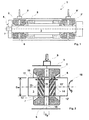
- a storage area 1 of an otherwise not shown turbocharger has at least one radial bearing 2,2 ', in which a rotor shaft 3 of a rotor 4 is rotatably mounted.
- the storage area 1 is surrounded by the bearing housing 5 of the exhaust gas turbocharger.
- the radial bearing 2, 2 ' has at least one fluid channel 6, with which fluid can be supplied to the layer region 7 or with which the fluid can be discharged from the layer region 7.
- a fluid film 8 is arranged, on which the rotor shaft 3 can slide.
- the fluid channel 6 is used inter alia with others in Fig. 1 Not shown means for continuous replacement of the fluid film 8.
- Via a fluid supply device 9,9 ' the fluid channel 6 and the radial bearing 2,2' are supplied with fluid.
- the fluid supply device 9,9 ' may be formed as a sickle groove.
- Fig. 2 is a section of the loading area 1 in the region of the radial bearing 2,2 'shown.
- a bearing shaft portion 10 of the rotor shaft 3 has a segment-like structure.
- an inner segment 11 is thus arranged on the rotor shaft 3.
- an outer segment 13, 13' is respectively arranged on the rotor shaft 3, so that the two outer segments 13, 13 'define the inner segment 11.
- the diameter of the rotor shaft 3 is denoted by D w and the diameter of the fluid channel 6 to D F.
- a plurality of transverse grooves 14 are positioned so that they are inclined with respect to the circumferential direction.
- the transverse grooves 14 in the direction of rotation 15 of the respective outer segment 13,13 'to the inner segment 11 extending.
- transverse grooves 14 extend straight here in a radial projection. Likewise, an embodiment is conceivable in which the transverse grooves 14 extend curved in a radial projection.
- a symmetrical embodiment of the transverse grooves 14 is shown, wherein the transverse grooves 14 with respect.
- the bearing center plane 16 are mirror image symmetrically positioned on the rotor shaft 3 in the bearing shaft portion 10.
- the fluid flow direction 17 extends from the inner segment 11 to the outer segments 13, 13 '.
- the length of the bearing shaft portion 10 is indicated by L W.
- Fig. 3 is a section of an outer segment 13,13 'shown.
- the fluid flow direction 17 is again running from the inner segment to the outer segment as shown and the direction of rotation 15 is analogous to the Fig. 2 , Furthermore, two sectional lines IV, V are shown, each in the FIGS. 4 and 5 are shown.
- Fig. 4a and 4b show two different embodiments of a transverse groove 14.
- Fig. 4a is shown in a rectangular shape while the Fig. 4b has a semicircular shape.
- the edges 18 of the transverse grooves 14 are provided with folds 19.
- the fold 19 may be formed as an edge break or rounding.
- the section V of Fig. 3 is in Fig. 5 shown. It shows a transverse groove 14, which is formed in the fluid flow direction 17 'within the transverse groove 14 with decreasing groove depth 20, 20'.
- 14 is also the distance in the transverse groove between the inner bearing portion 7 and the transverse groove bottom 21 in the fluid flow direction 17 decreasing.
- FIGS. 6a to 6d different embodiments of the bearing shaft portion 10 are shown.
- the fluid flow direction 17 extends from the inner segment 11 to the outer segments 13, 13 'and the direction of rotation 15 of the rotor shaft 3 as shown.
- the bearing center plane 16 is shown here a symmetrical embodiment. However, it is also an asymmetrical design conceivable, wherein the transverse grooves 14 are arranged offset from one another in the circumferential direction.
- This angle ⁇ may preferably have a value between 15 and 30 °, particularly preferably a value between 30 and 45 ° and very particularly preferably a value between 45 and 60 °.
- Fig. 6b shown embodiment is analogous to the embodiment of Fig. 6a constructed, with the only difference that the fluid flow direction 17 is oriented from the outer segment into the inner segment. As a result, the transverse grooves are running as shown.
- the Fig. 6c shows an embodiment of the bearing shaft portion 10 with a groove-free inner segment 11.
- the width of the inner segment is denoted by B i , while the widths of the outer segments with B a , B a 'are marked.
- the widths B a , B a 'of the outer segments are the same size.
- the embodiment of the Fig. 6d has an annular groove 23 extending over the entire inner segment region. Preference is given to the transverse grooves in a connection region 24,24 'of the respective outer segment 13,13' formed on the inner segment 11 so that they are fluidly connected to the annular groove 23.
- the deepest point of the transverse groove bottom 21 is preferably located at the level of the annular groove bottom 25.
- the transverse groove base 21 can be arranged below the annular groove bottom 25 viewed from the rotor shaft surface.
Landscapes
- Engineering & Computer Science (AREA)
- General Engineering & Computer Science (AREA)
- Mechanical Engineering (AREA)
- Chemical & Material Sciences (AREA)
- Oil, Petroleum & Natural Gas (AREA)
- Physics & Mathematics (AREA)
- Fluid Mechanics (AREA)
- Supercharger (AREA)
- Sliding-Contact Bearings (AREA)
- Support Of The Bearing (AREA)
Description
- Die vorliegende Erfindung betrifft einen Abgasturbolader mit einer Rotorwelle, mit den Merkmalen des Oberbegriffs des Anspruchs 1.
- Aus der
EP 1 972 759 A2 ist ein Abgasturbolader bekannt, der in einem Radiallager, das eine Welle des Abgasturboladers rotationsbeweglich lagert, mehrere axial verlaufende Nuten aufweist. Dabei können die Nuten im Profil eine V- oder U-Form aufweisen. Die axial verlaufenden Nuten ermöglichen dabei vorteilhaft eine Fortentwicklung der Rotordynamik eines solchen Abgasturboladers, da ein Abgasturbolader mit derartigen axial verlaufenden Nuten in den Radiallagern eine erhöhte Resistenz gegenüber einer als selbsterregte subsynchronische Schwingung bekannte Bewegung der Rotorwelle aufweist. Dies gelingt durch eine Verminderung von Fluidwirbeln in dem zwischen dem Radiallager und der Rotorwelle angeordneten Fluidfilm, insbesondere im niederen Lastbereich. - Siehe auch GB-A-2335713.
- Von der Bezeichnung Fluidwirbel ist ebenfalls der Fachbegriff "oil whirl" umfasst. Das Auftreten solcher Fluidwirbel ist bei Verwendung von Gleitlagern in Ladeeinrichtungen bekannt und wird aufgrund der rotierenden Rotorwelle um die Lagermitte verursacht, wobei in dem zwischen dem Radiallager und der Rotorwelle angeordneten Fluidfilm innere und äußere Fluidwirbel unterschieden werden können. Fluidwirbel treten insbesondere auch bei hochtourigen Drehzahlen auf und verursachen insbesondere bei höheren Drehzahlen, eine taumelnde Bewegung des Rotors bzw. der Rotorwelle in zylindrischen und konischen Schwingungsmoden, die auch als "selbsterregte subsynchronische Schwingung" bekannt ist. Insbesondere der innere Fluidwirbel induziert aufgrund der Strömung des inneren Fluidfilms einen Konstantton, dessen von der jeweiligen Fluidtemperatur abhängige Frequenz in einer Größenordnung der Halbfrequenz der Rotordrehzahl liegt. Dabei kann der durch den Fluidwirbel induzierte Konstantton eine Breitbandfrequenz von 600 bis 900 Hz aufweisen, die bei entsprechenden Motordrehzahlen von 1500 bis 3500 U/min auftreten. Die durch den Fluidwirbel auftretende selbsterregte Schwingung, die die Rotorauslenkung zu einem instabilen Zustand erregen kann, kann bei ungünstigen Betriebsbedingungen zu einem Lagerschaden führen. Eine derartige destruktive Schwingung kann dann auftreten, wenn die Frequenz des Konstanttons des Fluidwirbels gleich der kritischen Frequenz der ersten Biegeordnung des Rotor-Lager-Systems ist.
- Des Weiteren kann bei derzeit üblichen Rotor-Lager-Systemen in Turbinen oder Ladeeinrichtungen ein häufiger Start-Stopp-Betrieb zu einem erhöhten Verschleiß des Rotor-Lager-Systems führen. Wird z. B. bei einem Kraftfahrzeug mit einer Ladeeinrichtung der Motor während z. B. einer Stadtfahrt und vor Verkehrsampeln kurz aus- und wieder eingeschaltet, so kann aufgrund eines Fluidmangels im Fluidfilm bei häufiger Anwendung des Start-Stopp-Betriebes und insbesondere beim Startbetrieb der Verschleiß am Radiallager bzw. auf der Rotorwelle vermehrt auftreten.
- Die vorliegende Erfindung beschäftigt mit dem Problem, für einen Abgasturbolader sowie für ein dazugehöriges Betriebsverfahren, eine verbesserte oder andere Ausführungsform anzugeben, die sich insbesondere durch einen reduzierten Verschleiß auszeichnet.
- Erfindungsgemäß wird dieses Problem durch den Gegenständ des unabhängigen Ansprüchs gelöst. Vorteilhafte Ausführungsformen sind Gegenstand der abhängigen Ansprüche.
- Die Erfindung beruht auf dem allgemeinen Gedanken, eine Rotorwelle des Abgasturboladers, die mit zumindest einem Lager-Wellenabschnitt in einem, insbesondere als Gleitlager ausgebildeten, Radiallager rotationsbeweglich und auf einem Fluidfilm gleitend angeordnet ist, zumindest in einem Lager-Wellenabschnitt in zwei am jeweiligen Radiallagerendbereich angeordnete Außensegmente und ein zwischen den Außensegmenten positioniertes Innensegment zu unterteilen, wobei zumindest in einem der Außensegmente zumindest eine gegenüber der Umfangsrichtung der Rotorwelle geneigt verlaufende Quernut angeordnet ist.
- Überraschenderweise wurde festgestellt, dass durch Anordnung von gegenüber einer Umfangsrichtung der Rotorwelle geneigt verlaufenden Quernuten in einem Lager-Wellenabschnitt der Rotorwelle, der Verschleiß von Rotorwelle und Radiallager sich erheblich verringern lässt.
- Die Rotorwelle trägt zum Beispiel ein Verdichterrad eines Verdichters des Abgasturboladers und/oder ein Turbinenrad einer Turbine des Abgasturboladers. Die Rotorwelle ist hierzu zweckmäßig in einem Lagergehäuse des Abgasturboladers drehbar gelagert. Das Lagergehäuse befindet sich dabei üblicherweise axial zwischen einem Verdichtergehäuse und einem Turbinengehäuse.
- Vorteilhaft stellt sich durch die zumindest eine in zumindest einem Außensegment angeordnete geneigte Quernut ein Pumpeneffekt ein, der durch die Bewegung der Rotorwelle zustande kommt. Aufgrund der Rotation der Rotorwelle wird durch eine bestimmte Lage der Quernut Fluid aus dem Fluidfilm des Innensegmentes in die Quernut hineingeschaufelt und entlang derselben zu dem zumindest einen Außensegment transportiert. Dadurch wird dem in dem zumindest einen Außensegment angeordneten Fluidfilm Fluid zugeführt. Somit gelingt es bei einem Startbetrieb der Rotorwelle den in dem Außensegment angeordneten Fluidfilm aufgrund des Pumpeneffektes durch die geneigte Quernut schneller aufzubauen, wodurch eine Verschleißminderung bei einem, insbesondere häufigen, Start-Stopp-Betrieb möglich ist. Des Weiteren ist der Druck in dem Fluidfilm zumindest in dem einen Außensegment in Abhängigkeit von der Drehzahl der Rotorwelle erhöht. Durch diesen erhöhten Druck im Fluidfilm bei laufendem Betrieb ist die Lagersteifigkeit erhöht und der Konstantton bzgl. des inneren Fluidwirbels verringert. Zudem ist aufgrund der erhöhten Lagersteifigkeit und der Verringerung des Konstanttons das Radiallager-Rotorwellen-System mit einer derartigen Quernut unempfindlicher gegen Schwingungen, Unwuchtschwingungen und Auslenkungen. Insgesamt ist dadurch der Verschleiß während des gesamten Betriebes einer solchen Ladeeinrichtung oder Turbine hinsichtlich des Radiallager-Rotorwellen-Systems deutlich verringert.
- Eine derartig ausgebildete Rotorwelle kann zusammen mit zumindest einem Turbinenrad als Rotor in einer Ladeeinrichtung oder einer Turbine verwendet werden. Dabei ist ein Lager-Wellenabschnitt der Rotorwelle in einem Radiallager angeordnet und auf einen zwischen dem Radiallager und der Rotorwelle angeordneten Fluidfilm gleitend und rotationsbeweglich positioniert.
- Das Radiallager kann dabei als rotierendes oder nicht-rotierendes Schwimmbuchsenlager ausgebildet sein. Ganz allgemein ist dabei die Verwendung eines Gleitlagers bevorzugt, wobei anstatt einem Schwimmbuchsenlager auch ein Festbuchsenlager zum Einsatz kommen kann. Das Radiallager weist zumindest einen im Wesentlichen radial verlaufenden Fluidkanal auf, der bevorzugt mittig in dem Radiallager angeordnet ist. Über diesen Fluidkanal kann der zwischen der Rotorwelle und dem Radiallager angeordnete Fluidfilm mit Fluid versorgt werden oder Fluid von dem Fluidfilm abtransportiert werden.
- Die Rotorwelle kann im Bereich des in dem Radiallager angeordneten Lager-Wellenabschnittes in mehrere Segmente unterteilt werden. Dabei ist auf der Rotorwelle in dem Lager-Wellenabschnitt jeweils im Radiallagerendbereich ein Außensegment angeordnet und zwischen den beiden Außensegmenten ein Innensegment. Dabei ist das Innensegment derartig positioniert, dass es im Wesentlichen im Bereich der Öffnung des Fluidkanals des Radiallagers angeordnet ist. Somit wird über das Innensegment dem Lager-Wellenabschnitt Fluid zugeführt oder von dem Lager-Wellenabschnitt abgeführt.
- In zumindest einem Außensegment ist zumindest eine Quernut positioniert. Dabei ist vorteilhaft in beiden Außensegmenten zumindest eine Quernut je Außensegment angeordnet. Besonders bevorzugt sind in jeweils einem Außensegment 8, 14, 16 oder 20 Quernuten angeordnet.
- Das Innensegment kann quernutfrei ausgebildet sein oder es kann sich zumindest eine in einem Außensegment angeordnete Quernut in das Innensegment hinein erstrecken. In beiden Fällen, quernutfrei oder zumindest eine Quernut aufweisend, kann das Innensegment mit zumindest einer in Umlaufrichtung verlaufenden Ringnut versehen sein. Bevorzugt weist das Innensegment nur eine Ringnut auf, die sich ganz besonders bevorzugt in Längsrichtung der Rotorwelle über das gesamte Innensegment hinweg erstreckt.
- Durch eine derartige Ringnut ist die Fluidzufuhr/-abfuhr über das Innensegment erleichtert. Ist zudem die zumindest eine Quernut in einem Anschlussbereich des Außensegmentes an das Innensegment fluidisch mit der Ringnut verbunden, so ist der Transport des Fluids zum Innensegment oder vom Innensegment weg vorteilhaft verbessert. Außerdem stellt das in der Ringnut angeordnete Fluid ein gewisses Fluidreservoir dar, das insbesondere beim Start-Stopp-Betrieb zum schnellen Aufbau des zwischen der Rotorwelle und dem Radiallager angeordneten und in dem Bereich der Außensegmente positionierten Fluidfilms verwendet werden kann.
- Die zumindest eine Quernut ist auf jeden Fall gegenüber der Umfangsrichtung der Rotorwelle geneigt verlaufend angeordnet. Die Orientierung der Quernut ist jedoch in Abhängigkeit der Drehrichtung und der axialen Strömungsrichtung des Fluids zu wählen.
- Dabei versteht man unter Umfangsrichtung die Richtung in der ein auf der Oberfläche der Rotorwelle verlaufender Umfang verläuft. Die Drehrichtung stellt die Richtung dar, in der sich die Rotorwelle dreht. Die Längsrichtung verläuft entlang der Längsachse der Rotorwelle. Die Fluidströmungsrichtung stellt diejenige Richtung dar, in der das Fluid im Bereich des Radiallagers fließt. Dabei können zwei Richtungen unterschieden werden. So kann über den Fluidkanal dem Radiallager Fluid zugeführt werden, sodass sich eine Fluidströmungsrichtung von dem Innensegment zum Außensegment einstellt. Wird über den Fluidkanal das Fluid aus dem Radiallager abgeführt, so ist eine Strömungsrichtung von dem zumindest einen Außensegment zum Innensegment gegeben.
- In Abhängigkeit von der Drehrichtung und der Fluidströmungsrichtung ist bei einer Strömungsrichtung vom Innensegment zum Außensegment die zumindest eine Quernut in Drehrichtung vom Außensegment zum Innensegment verlaufend. Bei einer Fluidströmungsrichtung vom Außensegment zum Innensegment ist in Drehrichtung die zumindest eine Quernut vom Innensegment zum Außensegment verlaufend. Um dabei die jeweilige Orientierung der Quernut zu ermitteln, setzt man auf dem Innensegment oder Außensegment auf und fährt auf der Rotorwelle in Drehrichtung und zur Umfangsrichtung geneigt zu dem jeweiligen anderen Segment. Dies ergibt dann die Orientierung der Quernut auf der Rotorwelle.
- Dabei ist die zumindest eine Quernut unter einem vorbestimmten Winkel zu einer auf einer Rotorwellenoberfläche gedachten Längsrichtung der Rotorwelle angeordnet. Dieser Winkel kann einen Wert von bevorzugt 15-30°, besonders bevorzugt von 30-45° und besonders bevorzugt von 45-60° einnehmen.
- Im Falle, dass die Quernuten in das Innensegment hineinragen, kann im Innensegment noch ein ringförmiger Bereich verbleiben, der quernutfrei ist. Die Quernuten können sich jedoch auch im Innensegment schneiden. Sind in beiden Außensegmenten Quernuten angeordnet, so können diese Quernuten symmetrisch in den Außensegmenten angeordnet sein, oder versetzt zueinander.
- Der Querschnitt einer solchen Quernut kann rechteckig, quadratisch oder dreieckig und/oder in Teilbereichen halbrund oder elypsoid sein. Bevorzugt sind die zur Rotorwellenoberfläche orientierten Kanten mit Abkantungen versehen. Diese Abkantung kann als Abrundung oder Kantenbruch sowie Anschrägung ausgebildet sein. Aufgrund der Abkantungen ist der Verschleiß, insbesondere im Radiallager, deutlich verringert.
- Aufgrund der Orientierung einer solchen Quernut wird, durch die Drehbewegung der Rotorwelle, das Fluid aus dem Fluidfilm in die Quernut hineingedrückt und entlang derselben in Strömungsrichtung transportiert. Durch diesen Pumpeneffekt kann der Druck in dem Fluidfilm im Bereich der Außensegmente erhöht werden und dadurch die Lagersteifigkeit verbessert werden.
- Vorteilhaft kann der Druckaufbau in dem Fluidfilm verbessert werden, durch eine abfallende Nuttiefe in Fluidströmungsrichtung entlang der Quernut. Durch den Pumpeneffekt wird Fluid entlang der Fluidströmungsrichtung innerhalb der Quernut transportiert und aufgrund der abfallenden Tiefe staut sich das Fluid entlang der Fluidströmungsrichtung in der Quernut zunehmend. Dadurch ist der Druckaufbau in dem Fluidfilm verbessert.
- Weitere wichtige Merkmale und Vorteile der Erfindung ergeben sich aus den Unteransprüchen, aus den Zeichnungen und aus der zugehörigen Figurenbeschreibung anhand der Zeichnungen.
- Es versteht sich, dass die vorstehend genannten und die nachstehend noch zu erläuternden Merkmale nicht nur in der jeweils angegebenen Kombination, sondern auch in anderen Kombinationen oder in Alleinstellung verwendbar sind, ohne den Rahmen der vorliegenden Erfindung zu verlassen.
- Bevorzugte Ausführungsbeispiele der Erfindung sind in den Zeichnungen dargestellt und werden in der nachfolgenden Beschreibung näher erläutert, wobei sich gleiche Bezugszeichen auf gleiche oder ähnliche oder funktional gleiche Bauteile beziehen.
- Es zeigen, jeweils schematisch:
- Fig. 1
- einen Lagerbereich eines Abgasturboladers,
- Fig. 2
- einen in einem Radiallager angeordneten Lager-Wellenabschnitt,
- Fig. 3
- mehrere in einem Außensegment angeordnete Quernuten,
- Fig. 4
- verschiedene Ausführungsformen eines Querschnittes der Quernut,
- Fig. 5
- eine abfallende Nuttiefe entlang der Fluidströmungsrichtung,
- Fig. 6
- mehrere Ausführungsformen eines Lager-Wellenabschnittes.
- Ein Lagerbereich 1 eines im übrigen nicht gezeigten Abgasturboladers weist zumindest ein Radiallager 2,2' auf, in dem eine Rotorwelle 3 eines Rotors 4 rotationsbeweglich gelagert ist. Üblicherweise wird der Lagerbereich 1 von dem Lagergehäuse 5 des Abgasturboladers umgeben.
- Das Radiallager 2,2' weist zumindest einen Fluidkanal 6 auf, mit dem dem Lagebereich 7 Fluid zugeführt werden kann oder mit dem von dem Lagebereich 7 das Fluid abführbar ist. Zwischen der Rotorwelle 3 und dem Radiallager 2,2' ist ein Fluidfilm 8 angeordnet, auf dem die Rotorwelle 3 gleiten kann. Der Fluidkanal 6 dient unter anderem mit anderen in
Fig. 1 nicht gezeigten Einrichtungen zum stetigen Austausch des Fluidfilms 8. Über eine Fluidversorgungseinrichtung 9,9' kann der Fluidkanal 6 sowie das Radiallager 2,2' mit Fluid versorgt werden. Die Fluidversorgungseinrichtung 9,9' kann als Sichelnut ausgebildet sein. - In
Fig. 2 ist ein Ausschnitt des Ladebereiches 1 im Bereich des Radiallagers 2,2' dargestellt. Dabei weist ein Lager-Wellenabschnitt 10 der Rotorwelle 3 eine segmentartige Struktur auf. Im Bereich des Fluidkanals 6 ist somit auf der Rotorwelle 3 ein Innensegment 11 angeordnet. Im jeweiligen Lagerendbereich 12,12' ist jeweils ein Außensegment 13,13' auf der Rotorwelle 3 angeordnet, sodass die beiden Außensegmente 13,13'das Innensegment 11 begrenzen. Dabei ist der Durchmesser der Rotorwelle 3 mit Dw gekennzeichnet und der Durchmesser des Fluidkanals 6 mit DF. - In den Außensegmenten 13,13' sind mehrere Quernuten 14 so positioniert, dass sie geneigt gegenüber der Umfangsrichtung verlaufen. Dabei sind die Quernuten 14 in Drehrichtung 15 vom jeweiligen Außensegment 13,13' zum Innensegment 11 verlaufend.
- Die Quernuten 14 erstrecken sich hier in einer Radialprojektion geradlinig. Ebenso ist eine Ausführungsform denkbar, bei der sich die Quernuten 14 in einer Radialprojektion gekrümmt erstrecken.
- In
Fig. 2 ist eine symmetrische Ausführungsform der Quernuten 14 dargestellt, wobei die Quernuten 14 bzgl. der Lagermittelebene 16 spiegelbildsymmetrisch auf der Rotorwelle 3 im Lager-Wellenabschnitt 10 positioniert sind. In dieser Ausführungsform verläuft die Fluidströmungsrichtung 17 vom Innensegment 11 zu den Außensegmenten 13,13'. Die Länge des Lager-Wellenabschnittes 10 ist mit LW gekennzeichnet. - In
Fig. 3 ist ein Ausschnitt eines Außensegmentes 13,13' dargestellt. Die Fluidströmungsrichtung 17 ist wieder vom Innensegment zum Außensegment wie eingezeichnet verlaufend und die Drehrichtung 15 verläuft analog derFig. 2 . Des Weiteren sind zwei Schnittlinien IV, V eingezeichnet, die jeweils in denFiguren 4 und 5 dargestellt sind. -
Fig. 4a und 4b zeigen zwei verschiedene Ausführungsformen einer Quernut 14. InFig. 4a ist eine rechteckige Form dargestellt, während dieFig. 4b eine halbrunde Form aufweist. In beiden Fällen sind die Kanten 18 der Quernuten 14 mit Abkantungen 19 versehen. Dabei kann die Abkantung 19 als Kantenbruch oder Abrundung ausgebildet sein. - Der Schnitt V der
Fig. 3 ist inFig. 5 dargestellt. Er zeigt eine Quernut 14, die in Fluidströmungsrichtung 17' innerhalb der Quernut 14 mit abfallender Nuttiefe 20, 20' ausgebildet ist. Dadurch ist ebenfalls im Bereich der Quernut 14 der Abstand zwischen dem Innenlagerbereich 7 und dem Quernutboden 21 in Fluidströmungsrichtung 17 absinkend. Durch diese abfallende Nuttiefenausbildung gelingt es, den Druck im Fluidfilm 8 schneller und höher einzustellen. - In den
Figuren 6a bis 6d sind unterschiedliche Ausführungsformen des Lager-Wellenabschnittes 10 dargestellt. In derFig. 6a verläuft die Fluidströmungsrichtung 17 vom Innensegment 11 zu den Außensegmenten 13,13' und die Drehrichtung 15 der Rotorwelle 3 wie eingezeichnet. Bzgl. der Lagermittelebene 16 ist hier eine symmetrische Ausführungsform dargestellt. Es ist aber ebenfalls eine unsymmetrische Ausbildung denkbar, wobei die Quernuten 14 in Umfangsrichtung versetzt zueinander angeordnet sind. Bzgl. einer auf der Rotorwellenoberfläche gedachten Längsrichtung 22 der Rotorwelle, ist die jeweilige Quernut unter einem Winkel β geneigt angeordnet. Dieser Winkel β kann bevorzugt einen Wert zwischen 15 und 30°, besonders bevorzugt einen Wert zwischen 30 und 45° und ganz besonders bevorzugt einen Wert zwischen 45 und 60° aufweisen. - Die in der
Fig. 6b aufgezeigte Ausführungsform ist analog der Ausführungsform derFig. 6a aufgebaut, mit dem einzigen Unterschied, dass die Fluidströmungsrichtung 17 vom Außensegment in das Innensegment orientiert ist. Demzufolge sind die Quernuten wie dargestellt verlaufend. - Die
Fig. 6c zeigt eine Ausführungsform des Lager-Wellenabschnittes 10 mit einem nutfreien Innensegment 11. Die Breite des Innensegmentes ist mit Bi bezeichnet, während der Breiten der Außensegmente mit Ba,Ba' gekennzeichnet sind. In einer besonders bevorzugten Ausführungsform sind die Breiten Ba,Ba' der Außensegmente gleich groß. - Die Ausführungsform der
Fig. 6d weist eine sich über den gesamten Innensegmentbereich erstreckende Ringnut 23 auf. Bevorzugt sind dabei die Quernuten in einem Anschlussbereich 24,24' des jeweiligen Außensegmentes 13,13' an das Innensegment 11 so ausgebildet, dass sie fluidisch mit der Ringnut 23 verbunden sind. Bevorzugt befindet sich dabei der tiefste Punkt des Quernutbodens 21 auf Höhe des Ringnutbodens 25. In einer weiteren Ausführungsform kann der Quernutboden 21 von der Rotorwellenoberfläche aus betrachtet auch unterhalb des Ringnutbodens 25 angeordnet sein.
Claims (9)
- Abgasturbolader mit einer Rotorwelle (3), die mit zumindest einem Lager-Wellenabschnitt (10) in einem als Gleitlager ausgebildeten Radiallager (2,2') rotationsbeweglich und auf einem Fluidfilm gleitend angeordnet ist, wobei- der zumindest eine Lager-Wellenabschnitt (10) in zwei am jeweiligen axialen Radiallagerendbereich (12,12') angeordnete Außensegmente (13,13') und ein zwischen den Außensegmenten (13,13') positioniertes Innensegment (11) unterteilt ist,- das Innensegment (11) im Wesentlichen im Bereich einer Öffnung eines Fluidkanals (6) des Radiallagers (2, 2') angeordnet ist- zumindest in einem der Außensegmente (13,13') zumindest eine gegenüber der Umfangsrichtung der Rotorwelle (3) geneigt verlaufende Quernut (14) angeordnet ist,dadurch gekennzeichnet,- dass eine Nuttiefe (20, 20') zumindest einer solchen Quernut (14) einen in einer Fluidströmungsrichtung (17) entlang der Quernut (14) kontinuierlich abnehmenden Verlauf aufweist,- dass der Abstand zwischen der Rotorwellen-Rotationsachse und dem quernutfreien Innensegment-Oberflächenbereich kleiner als der Abstand zwischen der Rotorwellen-Rotationsachse und einem quernutfreien Außensegment-Oberflächenbereich ist.
- Abgasturbolader nach Anspruch 1,
dadurch gekennzeichnet, dass
bei der Fluidströmungsrichtung (17) von dem Innensegment (11) zu den Außensegmenten (13,13') die zumindest eine Quernut (14) entlang einer Drehrichtung (15) der Rotorwelle (3) von dem jeweiligen Außensegment (13,13') zum Innensegment (11) verläuft oder
bei einer Fluidströmungsrichtung (17) von den Außensegmenten (13,13') zu dem Innensegment (11) die zumindest eine Quernut (14) entlang der Drehrichtung (15) von dem Innensegment (11) zu dem jeweiligen Außensegment (13,13') verläuft. - Abgasturbolader nach einem oder mehreren der vorhergehenden Ansprüche,
dadurch gekennzeichnet, dass
zumindest eine solche Quernut (14) in einem vorbestimmten Winkel β zu einer auf einer Rotorwellenoberfläche gedachten Längsrichtung (22) der Rotorwelle (3) angeordnet ist. - Abgasturbolader nach einem oder mehreren der vorhergehenden Ansprüche,
dadurch gekennzeichnet, dass
zumindest eine solche Quernut (14) in das Innensegment (11) hineinragt und/oder
zumindest zwei solche Quernuten (14) im Innensegment (11) miteinander verbunden sind. - Abgasturbolader nach einem oder mehreren der vorhergehenden Ansprüche,
dadurch gekennzeichnet, dass
ein Abstand zwischen einer Rotorwellen-Rotationsachse und einem quernutfreien Innensegment-Oberflächenbereich gleich einem Abstand zwischen der Rotorwellen-Rotationsachse und einem quernutfreien Außensegment-Oberflächenbereich ist. - Abgasturbolader nach einem der Ansprüche 1 bis 3,
dadurch gekennzeichnet, dass
der Abstand zwischen der Rotorwellen-Rotationsachse und dem quernutfreien Innensegment-Oberflächenbereich gleich einem Abstand zwischen der Rotorwellen-Rotationsachse und einer tiefsten Stelle der zumindest einen Quernut (14) in einem Anschlußbereich (24) derselben an das Innensegment (11) ist. - Abgasturbolader nach einem oder mehreren der vorhergehenden Ansprüche,
dadurch gekennzeichnet, dass
die Nuttiefe (20, 20') zumindest einer solchen Quernut (14) entlang einer Fluidströmungsrichtung (17') innerhalb der Quernut (14) abnimmt. - Abgasturbolader nach einem oder mehreren der vorhergehenden Ansprüche,
dadurch gekennzeichnet, dass
die Nutkanten (18) zumindest einer solchen Quernut (14) eine Abrundung (19), eine Abkantung (19) oder einen Kantenbruch (19) aufweisen. - Abgasturbolader nach einem oder mehreren der vorhergehenden Ansprüche,
dadurch gekennzeichnet, dass
der Querschnitt zumindest einer solchen Quernut (14) rechteckig und/oder zumindest teilweise elipsoid und/oder zumindest teilweise halbrund ausgebildet ist.
Applications Claiming Priority (2)
| Application Number | Priority Date | Filing Date | Title |
|---|---|---|---|
| DE102010022574A DE102010022574A1 (de) | 2010-06-02 | 2010-06-02 | Rotorwelle mit Gleitlager |
| PCT/EP2011/058526 WO2011151231A1 (de) | 2010-06-02 | 2011-05-25 | Abgasturbolader mit gleitlager zur verminderung von fluidwirbeln |
Publications (2)
| Publication Number | Publication Date |
|---|---|
| EP2576996A1 EP2576996A1 (de) | 2013-04-10 |
| EP2576996B1 true EP2576996B1 (de) | 2015-07-15 |
Family
ID=44359492
Family Applications (1)
| Application Number | Title | Priority Date | Filing Date |
|---|---|---|---|
| EP11721317.3A Not-in-force EP2576996B1 (de) | 2010-06-02 | 2011-05-25 | Abgasturbolader mit gleitlager zur verminderung von fluidwirbeln |
Country Status (4)
| Country | Link |
|---|---|
| US (1) | US20130129506A1 (de) |
| EP (1) | EP2576996B1 (de) |
| DE (1) | DE102010022574A1 (de) |
| WO (1) | WO2011151231A1 (de) |
Families Citing this family (9)
| Publication number | Priority date | Publication date | Assignee | Title |
|---|---|---|---|---|
| DE102010052892A1 (de) * | 2010-12-01 | 2012-06-06 | Voith Patent Gmbh | Lageranordnung für eine Welle eines Turbinenrades |
| DE102012202341A1 (de) * | 2012-02-16 | 2013-08-22 | Continental Automotive Gmbh | Radiallager für einen Abgasturbolader |
| CN104283344A (zh) * | 2014-05-28 | 2015-01-14 | 莱克电气股份有限公司 | 一种转子及其加工装配方法 |
| DE112015003803T5 (de) * | 2014-08-19 | 2017-05-04 | Borgwarner Inc. | Abgasturbolader |
| EP3315802A1 (de) | 2016-10-31 | 2018-05-02 | Fischer Engineering Solutions AG | Rotationssystem mit axialer gaslagerung |
| CN106763192B (zh) * | 2017-03-31 | 2022-05-27 | 河北工业大学 | 可承受径向和轴向力且具有自动换向供油功能的浮环轴承 |
| CN109751333B (zh) * | 2017-11-03 | 2023-04-14 | 台达电子工业股份有限公司 | 轴承结构 |
| EP3916252A1 (de) * | 2020-05-28 | 2021-12-01 | Rolls-Royce Deutschland Ltd & Co KG | System und verfahren zur überwachung eines gleitlagers |
| DE102022124129A1 (de) * | 2022-09-20 | 2024-03-21 | Zf Cv Systems Global Gmbh | Folienlager und Lagerbock zum Aufnehmen eines Folienlagers |
Family Cites Families (25)
| Publication number | Priority date | Publication date | Assignee | Title |
|---|---|---|---|---|
| NL145931B (nl) * | 1965-05-21 | 1975-05-15 | Tno | Inrichting voorzien van een aero- of hydrostatisch leger. |
| GB1316970A (en) * | 1969-08-26 | 1973-05-16 | Coventry Corp Of The City Of | Hydrostatic/hydrodynamic shaft bearing arrangements |
| NL7609817A (nl) * | 1976-09-03 | 1978-03-07 | Philips Nv | Lager. |
| US4366993A (en) * | 1980-01-07 | 1983-01-04 | Nippon Telegraph & Telephone Corp. | Gas bearings |
| JPS58149415A (ja) * | 1982-02-26 | 1983-09-05 | Hitachi Ltd | 制振軸受 |
| JPS5973624A (ja) * | 1982-10-18 | 1984-04-25 | Aisin Seiki Co Ltd | タ−ボチヤ−ジヤ用軸受装置 |
| JP2516967B2 (ja) * | 1987-04-30 | 1996-07-24 | 松下電器産業株式会社 | 軸受装置 |
| JPH044310A (ja) * | 1990-04-18 | 1992-01-08 | Matsushita Electric Ind Co Ltd | 動圧型気体軸受装置 |
| DE4230037A1 (de) * | 1991-09-09 | 1993-03-11 | Aisin Seiki | Zentrifugal-aufladegeblaese |
| JP2902262B2 (ja) * | 1993-03-29 | 1999-06-07 | 光洋精工株式会社 | 動圧軸受 |
| JPH07259849A (ja) * | 1994-03-24 | 1995-10-09 | Konica Corp | 動圧軸受 |
| US5483570A (en) * | 1994-06-24 | 1996-01-09 | General Electric Company | Bearings for x-ray tubes |
| US5941534A (en) * | 1994-10-12 | 1999-08-24 | Honda Giken Kogyo Kabushiki Kaisha | Hydraulic seal system |
| JP3069039B2 (ja) * | 1996-02-02 | 2000-07-24 | 日本電産コパル電子株式会社 | 動圧気体軸受 |
| US6427330B1 (en) * | 1997-10-07 | 2002-08-06 | Sankyo Seiki Mfg. Co., Ltd. | Method for forming a lubricant coating on a hydrodynamic bearing apparatus by electrode positioning |
| GB2335713A (en) * | 1998-03-27 | 1999-09-29 | Aisin Seiki | Air bearings and their use in hybrid charger |
| EP1024294A3 (de) * | 1999-01-29 | 2002-03-13 | Ibiden Co., Ltd. | Motor und Turbomolekularpumpe |
| JP3332357B2 (ja) * | 1999-07-26 | 2002-10-07 | 住友ゴム工業株式会社 | 空気入りタイヤ |
| EP1132633A4 (de) * | 1999-09-17 | 2006-08-16 | Sumitomo Electric Industries | Dynamisches drucklager mit verbesserten starteigenschaften |
| JP4152553B2 (ja) * | 2000-02-10 | 2008-09-17 | Thk株式会社 | タービンロータを備えたスピンドル装置 |
| JP4243928B2 (ja) * | 2002-02-06 | 2009-03-25 | Thk株式会社 | ロータ・ステータ型ホモジナイザー |
| US7448805B2 (en) * | 2004-11-02 | 2008-11-11 | Matsushita Electric Industrial Co., Ltd. | Thrust dynamic pressure bearing, spindle motor using thereof, and information recording/reproducing device using the spindle motor |
| TWI273187B (en) * | 2005-01-28 | 2007-02-11 | Foxconn Tech Co Ltd | Fluid dynamic bearing |
| US7637663B2 (en) * | 2006-06-15 | 2009-12-29 | Hitachi Global Storage Technologies Netherlands B.V. | Fluid bearing with a variable depth groove |
| US7670056B2 (en) | 2007-03-22 | 2010-03-02 | Honeywell International Inc. | Stepped outer diameter semi-floating bearing |
-
2010
- 2010-06-02 DE DE102010022574A patent/DE102010022574A1/de not_active Withdrawn
-
2011
- 2011-05-25 US US13/701,430 patent/US20130129506A1/en not_active Abandoned
- 2011-05-25 WO PCT/EP2011/058526 patent/WO2011151231A1/de not_active Ceased
- 2011-05-25 EP EP11721317.3A patent/EP2576996B1/de not_active Not-in-force
Also Published As
| Publication number | Publication date |
|---|---|
| DE102010022574A1 (de) | 2011-12-08 |
| US20130129506A1 (en) | 2013-05-23 |
| WO2011151231A1 (de) | 2011-12-08 |
| EP2576996A1 (de) | 2013-04-10 |
Similar Documents
| Publication | Publication Date | Title |
|---|---|---|
| EP2576996B1 (de) | Abgasturbolader mit gleitlager zur verminderung von fluidwirbeln | |
| DE112015000855B4 (de) | Auswuchtverfahren für einen Turbolader | |
| DE69108523T2 (de) | Lager für Turbolader. | |
| EP1355043A1 (de) | Laufschaufel für eine Turbomaschine | |
| EP2002126A2 (de) | Kreiselpumpe mit koaxialer magnetkupplung | |
| DE112013001368T5 (de) | Turbolader mit Axiallager zur Bereitstellung von kombinierten Zapfen- und Axiallager-Funktionen | |
| EP3762624B1 (de) | Abgasturbolader mit einem hydrodynamischen gleitlager oder lageranordnung mit einem hydrodynamischen gleitlager | |
| EP2884054A1 (de) | Verstellbare Leitschaufel mit Kegelstumpf in einer Lageranordnung | |
| DE3840487A1 (de) | Dichtung fuer eine zylinderflaeche | |
| EP2599979B1 (de) | Ladeeinrichtung | |
| DE102008060369A1 (de) | Hydrodynamische Radialgleitlagerung | |
| EP2716874B1 (de) | Leitschaufelkranz, Montageverfahren und Strömungsmaschine | |
| WO2014044363A1 (de) | Lagervorrichtung und abgasturbolader | |
| DE102016222625A1 (de) | Lagerbuchse für eine Welle eines Turboladers | |
| EP2994615A1 (de) | Rotor für eine thermische strömungsmaschine | |
| DE102017207173B4 (de) | Turbolader mit Sollbruchstelle für eine Brennkraftmaschine | |
| DE202017100779U1 (de) | Ölabscheider mit geteilter Antriebskammer | |
| DE102012202341A1 (de) | Radiallager für einen Abgasturbolader | |
| DE102008033814A1 (de) | Lagerabschnitt für einen Abgasturbolader und Abgasturbolader | |
| DE112018004771T5 (de) | Turbolader | |
| EP3601739B1 (de) | Turbolader für eine brennkraftmaschine sowie turbinenrad | |
| DE102016113718B3 (de) | Gleitgelagerte doppelwandige Rotornabe für eine Windenergieanlage | |
| DE112021003728B4 (de) | Lager und Turbolader | |
| WO2013182306A1 (de) | Hydraulische dichtungsanordnung | |
| EP3792451B1 (de) | Verdichterstufe mit variabler statorschaufelneigung |
Legal Events
| Date | Code | Title | Description |
|---|---|---|---|
| PUAI | Public reference made under article 153(3) epc to a published international application that has entered the european phase |
Free format text: ORIGINAL CODE: 0009012 |
|
| 17P | Request for examination filed |
Effective date: 20121115 |
|
| AK | Designated contracting states |
Kind code of ref document: A1 Designated state(s): AL AT BE BG CH CY CZ DE DK EE ES FI FR GB GR HR HU IE IS IT LI LT LU LV MC MK MT NL NO PL PT RO RS SE SI SK SM TR |
|
| DAX | Request for extension of the european patent (deleted) | ||
| GRAP | Despatch of communication of intention to grant a patent |
Free format text: ORIGINAL CODE: EPIDOSNIGR1 |
|
| INTG | Intention to grant announced |
Effective date: 20150310 |
|
| GRAS | Grant fee paid |
Free format text: ORIGINAL CODE: EPIDOSNIGR3 |
|
| GRAA | (expected) grant |
Free format text: ORIGINAL CODE: 0009210 |
|
| AK | Designated contracting states |
Kind code of ref document: B1 Designated state(s): AL AT BE BG CH CY CZ DE DK EE ES FI FR GB GR HR HU IE IS IT LI LT LU LV MC MK MT NL NO PL PT RO RS SE SI SK SM TR |
|
| REG | Reference to a national code |
Ref country code: CH Ref legal event code: EP Ref country code: GB Ref legal event code: FG4D Free format text: NOT ENGLISH |
|
| REG | Reference to a national code |
Ref country code: IE Ref legal event code: FG4D Free format text: LANGUAGE OF EP DOCUMENT: GERMAN |
|
| REG | Reference to a national code |
Ref country code: AT Ref legal event code: REF Ref document number: 736920 Country of ref document: AT Kind code of ref document: T Effective date: 20150815 |
|
| REG | Reference to a national code |
Ref country code: DE Ref legal event code: R096 Ref document number: 502011007335 Country of ref document: DE |
|
| REG | Reference to a national code |
Ref country code: NL Ref legal event code: MP Effective date: 20150715 |
|
| REG | Reference to a national code |
Ref country code: LT Ref legal event code: MG4D |
|
| PG25 | Lapsed in a contracting state [announced via postgrant information from national office to epo] |
Ref country code: GR Free format text: LAPSE BECAUSE OF FAILURE TO SUBMIT A TRANSLATION OF THE DESCRIPTION OR TO PAY THE FEE WITHIN THE PRESCRIBED TIME-LIMIT Effective date: 20151016 Ref country code: LT Free format text: LAPSE BECAUSE OF FAILURE TO SUBMIT A TRANSLATION OF THE DESCRIPTION OR TO PAY THE FEE WITHIN THE PRESCRIBED TIME-LIMIT Effective date: 20150715 Ref country code: LV Free format text: LAPSE BECAUSE OF FAILURE TO SUBMIT A TRANSLATION OF THE DESCRIPTION OR TO PAY THE FEE WITHIN THE PRESCRIBED TIME-LIMIT Effective date: 20150715 Ref country code: FI Free format text: LAPSE BECAUSE OF FAILURE TO SUBMIT A TRANSLATION OF THE DESCRIPTION OR TO PAY THE FEE WITHIN THE PRESCRIBED TIME-LIMIT Effective date: 20150715 Ref country code: NO Free format text: LAPSE BECAUSE OF FAILURE TO SUBMIT A TRANSLATION OF THE DESCRIPTION OR TO PAY THE FEE WITHIN THE PRESCRIBED TIME-LIMIT Effective date: 20151015 |
|
| PG25 | Lapsed in a contracting state [announced via postgrant information from national office to epo] |
Ref country code: PL Free format text: LAPSE BECAUSE OF FAILURE TO SUBMIT A TRANSLATION OF THE DESCRIPTION OR TO PAY THE FEE WITHIN THE PRESCRIBED TIME-LIMIT Effective date: 20150715 Ref country code: RS Free format text: LAPSE BECAUSE OF FAILURE TO SUBMIT A TRANSLATION OF THE DESCRIPTION OR TO PAY THE FEE WITHIN THE PRESCRIBED TIME-LIMIT Effective date: 20150715 Ref country code: HR Free format text: LAPSE BECAUSE OF FAILURE TO SUBMIT A TRANSLATION OF THE DESCRIPTION OR TO PAY THE FEE WITHIN THE PRESCRIBED TIME-LIMIT Effective date: 20150715 Ref country code: ES Free format text: LAPSE BECAUSE OF FAILURE TO SUBMIT A TRANSLATION OF THE DESCRIPTION OR TO PAY THE FEE WITHIN THE PRESCRIBED TIME-LIMIT Effective date: 20150715 Ref country code: SE Free format text: LAPSE BECAUSE OF FAILURE TO SUBMIT A TRANSLATION OF THE DESCRIPTION OR TO PAY THE FEE WITHIN THE PRESCRIBED TIME-LIMIT Effective date: 20150715 Ref country code: PT Free format text: LAPSE BECAUSE OF FAILURE TO SUBMIT A TRANSLATION OF THE DESCRIPTION OR TO PAY THE FEE WITHIN THE PRESCRIBED TIME-LIMIT Effective date: 20151116 |
|
| REG | Reference to a national code |
Ref country code: DE Ref legal event code: R097 Ref document number: 502011007335 Country of ref document: DE |
|
| PG25 | Lapsed in a contracting state [announced via postgrant information from national office to epo] |
Ref country code: CZ Free format text: LAPSE BECAUSE OF FAILURE TO SUBMIT A TRANSLATION OF THE DESCRIPTION OR TO PAY THE FEE WITHIN THE PRESCRIBED TIME-LIMIT Effective date: 20150715 Ref country code: SK Free format text: LAPSE BECAUSE OF FAILURE TO SUBMIT A TRANSLATION OF THE DESCRIPTION OR TO PAY THE FEE WITHIN THE PRESCRIBED TIME-LIMIT Effective date: 20150715 Ref country code: IT Free format text: LAPSE BECAUSE OF FAILURE TO SUBMIT A TRANSLATION OF THE DESCRIPTION OR TO PAY THE FEE WITHIN THE PRESCRIBED TIME-LIMIT Effective date: 20150715 Ref country code: EE Free format text: LAPSE BECAUSE OF FAILURE TO SUBMIT A TRANSLATION OF THE DESCRIPTION OR TO PAY THE FEE WITHIN THE PRESCRIBED TIME-LIMIT Effective date: 20150715 Ref country code: DK Free format text: LAPSE BECAUSE OF FAILURE TO SUBMIT A TRANSLATION OF THE DESCRIPTION OR TO PAY THE FEE WITHIN THE PRESCRIBED TIME-LIMIT Effective date: 20150715 |
|
| PLBE | No opposition filed within time limit |
Free format text: ORIGINAL CODE: 0009261 |
|
| STAA | Information on the status of an ep patent application or granted ep patent |
Free format text: STATUS: NO OPPOSITION FILED WITHIN TIME LIMIT |
|
| PG25 | Lapsed in a contracting state [announced via postgrant information from national office to epo] |
Ref country code: RO Free format text: LAPSE BECAUSE OF FAILURE TO SUBMIT A TRANSLATION OF THE DESCRIPTION OR TO PAY THE FEE WITHIN THE PRESCRIBED TIME-LIMIT Effective date: 20150715 |
|
| REG | Reference to a national code |
Ref country code: FR Ref legal event code: PLFP Year of fee payment: 6 |
|
| 26N | No opposition filed |
Effective date: 20160418 |
|
| PG25 | Lapsed in a contracting state [announced via postgrant information from national office to epo] |
Ref country code: IS Free format text: LAPSE BECAUSE OF FAILURE TO SUBMIT A TRANSLATION OF THE DESCRIPTION OR TO PAY THE FEE WITHIN THE PRESCRIBED TIME-LIMIT Effective date: 20150715 |
|
| PG25 | Lapsed in a contracting state [announced via postgrant information from national office to epo] |
Ref country code: BE Free format text: LAPSE BECAUSE OF NON-PAYMENT OF DUE FEES Effective date: 20160531 Ref country code: SI Free format text: LAPSE BECAUSE OF FAILURE TO SUBMIT A TRANSLATION OF THE DESCRIPTION OR TO PAY THE FEE WITHIN THE PRESCRIBED TIME-LIMIT Effective date: 20150715 |
|
| PG25 | Lapsed in a contracting state [announced via postgrant information from national office to epo] |
Ref country code: LU Free format text: LAPSE BECAUSE OF FAILURE TO SUBMIT A TRANSLATION OF THE DESCRIPTION OR TO PAY THE FEE WITHIN THE PRESCRIBED TIME-LIMIT Effective date: 20160525 |
|
| REG | Reference to a national code |
Ref country code: CH Ref legal event code: PL |
|
| PG25 | Lapsed in a contracting state [announced via postgrant information from national office to epo] |
Ref country code: LI Free format text: LAPSE BECAUSE OF NON-PAYMENT OF DUE FEES Effective date: 20160531 Ref country code: CH Free format text: LAPSE BECAUSE OF NON-PAYMENT OF DUE FEES Effective date: 20160531 |
|
| REG | Reference to a national code |
Ref country code: IE Ref legal event code: MM4A |
|
| REG | Reference to a national code |
Ref country code: FR Ref legal event code: PLFP Year of fee payment: 7 |
|
| PG25 | Lapsed in a contracting state [announced via postgrant information from national office to epo] |
Ref country code: IE Free format text: LAPSE BECAUSE OF NON-PAYMENT OF DUE FEES Effective date: 20160525 |
|
| PG25 | Lapsed in a contracting state [announced via postgrant information from national office to epo] |
Ref country code: NL Free format text: LAPSE BECAUSE OF FAILURE TO SUBMIT A TRANSLATION OF THE DESCRIPTION OR TO PAY THE FEE WITHIN THE PRESCRIBED TIME-LIMIT Effective date: 20150715 |
|
| REG | Reference to a national code |
Ref country code: AT Ref legal event code: MM01 Ref document number: 736920 Country of ref document: AT Kind code of ref document: T Effective date: 20160525 |
|
| PG25 | Lapsed in a contracting state [announced via postgrant information from national office to epo] |
Ref country code: AT Free format text: LAPSE BECAUSE OF NON-PAYMENT OF DUE FEES Effective date: 20160525 |
|
| REG | Reference to a national code |
Ref country code: FR Ref legal event code: PLFP Year of fee payment: 8 |
|
| PG25 | Lapsed in a contracting state [announced via postgrant information from national office to epo] |
Ref country code: HU Free format text: LAPSE BECAUSE OF FAILURE TO SUBMIT A TRANSLATION OF THE DESCRIPTION OR TO PAY THE FEE WITHIN THE PRESCRIBED TIME-LIMIT; INVALID AB INITIO Effective date: 20110525 Ref country code: SM Free format text: LAPSE BECAUSE OF FAILURE TO SUBMIT A TRANSLATION OF THE DESCRIPTION OR TO PAY THE FEE WITHIN THE PRESCRIBED TIME-LIMIT Effective date: 20150715 Ref country code: CY Free format text: LAPSE BECAUSE OF FAILURE TO SUBMIT A TRANSLATION OF THE DESCRIPTION OR TO PAY THE FEE WITHIN THE PRESCRIBED TIME-LIMIT Effective date: 20150715 |
|
| REG | Reference to a national code |
Ref country code: DE Ref legal event code: R082 Ref document number: 502011007335 Country of ref document: DE Representative=s name: BRP RENAUD UND PARTNER MBB RECHTSANWAELTE PATE, DE Ref country code: DE Ref legal event code: R081 Ref document number: 502011007335 Country of ref document: DE Owner name: BMTS TECHNOLOGY GMBH & CO. KG, DE Free format text: FORMER OWNER: BOSCH MAHLE TURBO SYSTEMS GMBH & CO. KG, 70376 STUTTGART, DE |
|
| PG25 | Lapsed in a contracting state [announced via postgrant information from national office to epo] |
Ref country code: MT Free format text: LAPSE BECAUSE OF FAILURE TO SUBMIT A TRANSLATION OF THE DESCRIPTION OR TO PAY THE FEE WITHIN THE PRESCRIBED TIME-LIMIT Effective date: 20150715 Ref country code: TR Free format text: LAPSE BECAUSE OF FAILURE TO SUBMIT A TRANSLATION OF THE DESCRIPTION OR TO PAY THE FEE WITHIN THE PRESCRIBED TIME-LIMIT Effective date: 20150715 Ref country code: MC Free format text: LAPSE BECAUSE OF FAILURE TO SUBMIT A TRANSLATION OF THE DESCRIPTION OR TO PAY THE FEE WITHIN THE PRESCRIBED TIME-LIMIT Effective date: 20150715 Ref country code: MK Free format text: LAPSE BECAUSE OF FAILURE TO SUBMIT A TRANSLATION OF THE DESCRIPTION OR TO PAY THE FEE WITHIN THE PRESCRIBED TIME-LIMIT Effective date: 20150715 |
|
| PG25 | Lapsed in a contracting state [announced via postgrant information from national office to epo] |
Ref country code: BG Free format text: LAPSE BECAUSE OF FAILURE TO SUBMIT A TRANSLATION OF THE DESCRIPTION OR TO PAY THE FEE WITHIN THE PRESCRIBED TIME-LIMIT Effective date: 20150715 |
|
| PG25 | Lapsed in a contracting state [announced via postgrant information from national office to epo] |
Ref country code: AL Free format text: LAPSE BECAUSE OF FAILURE TO SUBMIT A TRANSLATION OF THE DESCRIPTION OR TO PAY THE FEE WITHIN THE PRESCRIBED TIME-LIMIT Effective date: 20150715 |
|
| PGFP | Annual fee paid to national office [announced via postgrant information from national office to epo] |
Ref country code: FR Payment date: 20200528 Year of fee payment: 10 |
|
| PGFP | Annual fee paid to national office [announced via postgrant information from national office to epo] |
Ref country code: GB Payment date: 20200528 Year of fee payment: 10 |
|
| PGFP | Annual fee paid to national office [announced via postgrant information from national office to epo] |
Ref country code: DE Payment date: 20200728 Year of fee payment: 10 |
|
| REG | Reference to a national code |
Ref country code: DE Ref legal event code: R119 Ref document number: 502011007335 Country of ref document: DE |
|
| GBPC | Gb: european patent ceased through non-payment of renewal fee |
Effective date: 20210525 |
|
| PG25 | Lapsed in a contracting state [announced via postgrant information from national office to epo] |
Ref country code: GB Free format text: LAPSE BECAUSE OF NON-PAYMENT OF DUE FEES Effective date: 20210525 Ref country code: DE Free format text: LAPSE BECAUSE OF NON-PAYMENT OF DUE FEES Effective date: 20211201 |
|
| PG25 | Lapsed in a contracting state [announced via postgrant information from national office to epo] |
Ref country code: FR Free format text: LAPSE BECAUSE OF NON-PAYMENT OF DUE FEES Effective date: 20210531 |