EP2577205B1 - Kühlsystem umfassend wärmeumlaufkühler und kühlturm und verfahren zum betrieb solch eines kühlsystems - Google Patents
Kühlsystem umfassend wärmeumlaufkühler und kühlturm und verfahren zum betrieb solch eines kühlsystems Download PDFInfo
- Publication number
- EP2577205B1 EP2577205B1 EP10737203.9A EP10737203A EP2577205B1 EP 2577205 B1 EP2577205 B1 EP 2577205B1 EP 10737203 A EP10737203 A EP 10737203A EP 2577205 B1 EP2577205 B1 EP 2577205B1
- Authority
- EP
- European Patent Office
- Prior art keywords
- cooling
- thermosyphon cooler
- controller
- cooling fluid
- temperature
- Prior art date
- Legal status (The legal status is an assumption and is not a legal conclusion. Google has not performed a legal analysis and makes no representation as to the accuracy of the status listed.)
- Active
Links
Images




Classifications
-
- F—MECHANICAL ENGINEERING; LIGHTING; HEATING; WEAPONS; BLASTING
- F28—HEAT EXCHANGE IN GENERAL
- F28B—STEAM OR VAPOUR CONDENSERS
- F28B1/00—Condensers in which the steam or vapour is separate from the cooling medium by walls, e.g. surface condenser
- F28B1/06—Condensers in which the steam or vapour is separate from the cooling medium by walls, e.g. surface condenser using air or other gas as the cooling medium
-
- F—MECHANICAL ENGINEERING; LIGHTING; HEATING; WEAPONS; BLASTING
- F24—HEATING; RANGES; VENTILATING
- F24F—AIR-CONDITIONING; AIR-HUMIDIFICATION; VENTILATION; USE OF AIR CURRENTS FOR SCREENING
- F24F5/00—Air-conditioning systems or apparatus not covered by F24F1/00 or F24F3/00, e.g. using solar heat or combined with household units such as an oven or water heater
- F24F5/0007—Air-conditioning systems or apparatus not covered by F24F1/00 or F24F3/00, e.g. using solar heat or combined with household units such as an oven or water heater cooling apparatus specially adapted for use in air-conditioning
- F24F5/0035—Air-conditioning systems or apparatus not covered by F24F1/00 or F24F3/00, e.g. using solar heat or combined with household units such as an oven or water heater cooling apparatus specially adapted for use in air-conditioning using evaporation
-
- F—MECHANICAL ENGINEERING; LIGHTING; HEATING; WEAPONS; BLASTING
- F25—REFRIGERATION OR COOLING; COMBINED HEATING AND REFRIGERATION SYSTEMS; HEAT PUMP SYSTEMS; MANUFACTURE OR STORAGE OF ICE; LIQUEFACTION SOLIDIFICATION OF GASES
- F25B—REFRIGERATION MACHINES, PLANTS OR SYSTEMS; COMBINED HEATING AND REFRIGERATION SYSTEMS; HEAT PUMP SYSTEMS
- F25B7/00—Compression machines, plants or systems, with cascade operation, i.e. with two or more circuits, the heat from the condenser of one circuit being absorbed by the evaporator of the next circuit
-
- F—MECHANICAL ENGINEERING; LIGHTING; HEATING; WEAPONS; BLASTING
- F28—HEAT EXCHANGE IN GENERAL
- F28B—STEAM OR VAPOUR CONDENSERS
- F28B1/00—Condensers in which the steam or vapour is separate from the cooling medium by walls, e.g. surface condenser
- F28B1/02—Condensers in which the steam or vapour is separate from the cooling medium by walls, e.g. surface condenser using water or other liquid as the cooling medium
-
- F—MECHANICAL ENGINEERING; LIGHTING; HEATING; WEAPONS; BLASTING
- F28—HEAT EXCHANGE IN GENERAL
- F28B—STEAM OR VAPOUR CONDENSERS
- F28B11/00—Controlling arrangements with features specially adapted for condensers
-
- F—MECHANICAL ENGINEERING; LIGHTING; HEATING; WEAPONS; BLASTING
- F28—HEAT EXCHANGE IN GENERAL
- F28B—STEAM OR VAPOUR CONDENSERS
- F28B9/00—Auxiliary systems, arrangements, or devices
- F28B9/04—Auxiliary systems, arrangements, or devices for feeding, collecting, and storing cooling water or other cooling liquid
- F28B9/06—Auxiliary systems, arrangements, or devices for feeding, collecting, and storing cooling water or other cooling liquid with provision for re-cooling the cooling water or other cooling liquid
-
- F—MECHANICAL ENGINEERING; LIGHTING; HEATING; WEAPONS; BLASTING
- F28—HEAT EXCHANGE IN GENERAL
- F28C—HEAT-EXCHANGE APPARATUS, NOT PROVIDED FOR IN ANOTHER SUBCLASS, IN WHICH THE HEAT-EXCHANGE MEDIA COME INTO DIRECT CONTACT WITHOUT CHEMICAL INTERACTION
- F28C1/00—Direct-contact trickle coolers, e.g. cooling towers
-
- F—MECHANICAL ENGINEERING; LIGHTING; HEATING; WEAPONS; BLASTING
- F28—HEAT EXCHANGE IN GENERAL
- F28C—HEAT-EXCHANGE APPARATUS, NOT PROVIDED FOR IN ANOTHER SUBCLASS, IN WHICH THE HEAT-EXCHANGE MEDIA COME INTO DIRECT CONTACT WITHOUT CHEMICAL INTERACTION
- F28C1/00—Direct-contact trickle coolers, e.g. cooling towers
- F28C1/14—Direct-contact trickle coolers, e.g. cooling towers comprising also a non-direct contact heat exchange
-
- F—MECHANICAL ENGINEERING; LIGHTING; HEATING; WEAPONS; BLASTING
- F28—HEAT EXCHANGE IN GENERAL
- F28D—HEAT-EXCHANGE APPARATUS, NOT PROVIDED FOR IN ANOTHER SUBCLASS, IN WHICH THE HEAT-EXCHANGE MEDIA DO NOT COME INTO DIRECT CONTACT
- F28D15/00—Heat-exchange apparatus with the intermediate heat-transfer medium in closed tubes passing into or through the conduit walls ; Heat-exchange apparatus employing intermediate heat-transfer medium or bodies
-
- F—MECHANICAL ENGINEERING; LIGHTING; HEATING; WEAPONS; BLASTING
- F28—HEAT EXCHANGE IN GENERAL
- F28D—HEAT-EXCHANGE APPARATUS, NOT PROVIDED FOR IN ANOTHER SUBCLASS, IN WHICH THE HEAT-EXCHANGE MEDIA DO NOT COME INTO DIRECT CONTACT
- F28D15/00—Heat-exchange apparatus with the intermediate heat-transfer medium in closed tubes passing into or through the conduit walls ; Heat-exchange apparatus employing intermediate heat-transfer medium or bodies
- F28D15/02—Heat-exchange apparatus with the intermediate heat-transfer medium in closed tubes passing into or through the conduit walls ; Heat-exchange apparatus employing intermediate heat-transfer medium or bodies in which the medium condenses and evaporates, e.g. heat pipes
- F28D15/025—Heat-exchange apparatus with the intermediate heat-transfer medium in closed tubes passing into or through the conduit walls ; Heat-exchange apparatus employing intermediate heat-transfer medium or bodies in which the medium condenses and evaporates, e.g. heat pipes having non-capillary condensate return means
-
- F—MECHANICAL ENGINEERING; LIGHTING; HEATING; WEAPONS; BLASTING
- F28—HEAT EXCHANGE IN GENERAL
- F28D—HEAT-EXCHANGE APPARATUS, NOT PROVIDED FOR IN ANOTHER SUBCLASS, IN WHICH THE HEAT-EXCHANGE MEDIA DO NOT COME INTO DIRECT CONTACT
- F28D15/00—Heat-exchange apparatus with the intermediate heat-transfer medium in closed tubes passing into or through the conduit walls ; Heat-exchange apparatus employing intermediate heat-transfer medium or bodies
- F28D15/02—Heat-exchange apparatus with the intermediate heat-transfer medium in closed tubes passing into or through the conduit walls ; Heat-exchange apparatus employing intermediate heat-transfer medium or bodies in which the medium condenses and evaporates, e.g. heat pipes
- F28D15/0266—Heat-exchange apparatus with the intermediate heat-transfer medium in closed tubes passing into or through the conduit walls ; Heat-exchange apparatus employing intermediate heat-transfer medium or bodies in which the medium condenses and evaporates, e.g. heat pipes with separate evaporating and condensing chambers connected by at least one conduit; Loop-type heat pipes; with multiple or common evaporating or condensing chambers
-
- F—MECHANICAL ENGINEERING; LIGHTING; HEATING; WEAPONS; BLASTING
- F28—HEAT EXCHANGE IN GENERAL
- F28D—HEAT-EXCHANGE APPARATUS, NOT PROVIDED FOR IN ANOTHER SUBCLASS, IN WHICH THE HEAT-EXCHANGE MEDIA DO NOT COME INTO DIRECT CONTACT
- F28D21/00—Heat-exchange apparatus not covered by any of the groups F28D1/00 - F28D20/00
- F28D21/0001—Recuperative heat exchangers
-
- F—MECHANICAL ENGINEERING; LIGHTING; HEATING; WEAPONS; BLASTING
- F28—HEAT EXCHANGE IN GENERAL
- F28D—HEAT-EXCHANGE APPARATUS, NOT PROVIDED FOR IN ANOTHER SUBCLASS, IN WHICH THE HEAT-EXCHANGE MEDIA DO NOT COME INTO DIRECT CONTACT
- F28D7/00—Heat-exchange apparatus having stationary tubular conduit assemblies for both heat-exchange media, the media being in contact with different sides of a conduit wall
- F28D7/10—Heat-exchange apparatus having stationary tubular conduit assemblies for both heat-exchange media, the media being in contact with different sides of a conduit wall the conduits being arranged one within the other, e.g. concentrically
- F28D7/103—Heat-exchange apparatus having stationary tubular conduit assemblies for both heat-exchange media, the media being in contact with different sides of a conduit wall the conduits being arranged one within the other, e.g. concentrically consisting of more than two coaxial conduits or modules of more than two coaxial conduits
-
- F—MECHANICAL ENGINEERING; LIGHTING; HEATING; WEAPONS; BLASTING
- F28—HEAT EXCHANGE IN GENERAL
- F28F—DETAILS OF HEAT-EXCHANGE AND HEAT-TRANSFER APPARATUS, OF GENERAL APPLICATION
- F28F19/00—Preventing the formation of deposits or corrosion, e.g. by using filters or scrapers
- F28F19/006—Preventing deposits of ice
-
- F—MECHANICAL ENGINEERING; LIGHTING; HEATING; WEAPONS; BLASTING
- F28—HEAT EXCHANGE IN GENERAL
- F28F—DETAILS OF HEAT-EXCHANGE AND HEAT-TRANSFER APPARATUS, OF GENERAL APPLICATION
- F28F27/00—Control arrangements or safety devices specially adapted for heat-exchange or heat-transfer apparatus
- F28F27/003—Control arrangements or safety devices specially adapted for heat-exchange or heat-transfer apparatus specially adapted for cooling towers
-
- F—MECHANICAL ENGINEERING; LIGHTING; HEATING; WEAPONS; BLASTING
- F28—HEAT EXCHANGE IN GENERAL
- F28F—DETAILS OF HEAT-EXCHANGE AND HEAT-TRANSFER APPARATUS, OF GENERAL APPLICATION
- F28F27/00—Control arrangements or safety devices specially adapted for heat-exchange or heat-transfer apparatus
- F28F27/02—Control arrangements or safety devices specially adapted for heat-exchange or heat-transfer apparatus for controlling the distribution of heat-exchange media between different channels
-
- F—MECHANICAL ENGINEERING; LIGHTING; HEATING; WEAPONS; BLASTING
- F28—HEAT EXCHANGE IN GENERAL
- F28C—HEAT-EXCHANGE APPARATUS, NOT PROVIDED FOR IN ANOTHER SUBCLASS, IN WHICH THE HEAT-EXCHANGE MEDIA COME INTO DIRECT CONTACT WITHOUT CHEMICAL INTERACTION
- F28C1/00—Direct-contact trickle coolers, e.g. cooling towers
- F28C2001/006—Systems comprising cooling towers, e.g. for recooling a cooling medium
-
- Y—GENERAL TAGGING OF NEW TECHNOLOGICAL DEVELOPMENTS; GENERAL TAGGING OF CROSS-SECTIONAL TECHNOLOGIES SPANNING OVER SEVERAL SECTIONS OF THE IPC; TECHNICAL SUBJECTS COVERED BY FORMER USPC CROSS-REFERENCE ART COLLECTIONS [XRACs] AND DIGESTS
- Y02—TECHNOLOGIES OR APPLICATIONS FOR MITIGATION OR ADAPTATION AGAINST CLIMATE CHANGE
- Y02B—CLIMATE CHANGE MITIGATION TECHNOLOGIES RELATED TO BUILDINGS, e.g. HOUSING, HOUSE APPLIANCES OR RELATED END-USER APPLICATIONS
- Y02B30/00—Energy efficient heating, ventilation or air conditioning [HVAC]
- Y02B30/70—Efficient control or regulation technologies, e.g. for control of refrigerant flow, motor or heating
-
- Y—GENERAL TAGGING OF NEW TECHNOLOGICAL DEVELOPMENTS; GENERAL TAGGING OF CROSS-SECTIONAL TECHNOLOGIES SPANNING OVER SEVERAL SECTIONS OF THE IPC; TECHNICAL SUBJECTS COVERED BY FORMER USPC CROSS-REFERENCE ART COLLECTIONS [XRACs] AND DIGESTS
- Y10—TECHNICAL SUBJECTS COVERED BY FORMER USPC
- Y10T—TECHNICAL SUBJECTS COVERED BY FORMER US CLASSIFICATION
- Y10T29/00—Metal working
- Y10T29/49—Method of mechanical manufacture
- Y10T29/4935—Heat exchanger or boiler making
- Y10T29/49359—Cooling apparatus making, e.g., air conditioner, refrigerator
Definitions
- the invention relates generally to thermosyphon coolers, and more particularly, to thermosyphon coolers for use in cooling systems that employ cooling towers.
- Cooling towers are often used to remove heat from heating, ventilating, and air conditioning (HVAC) systems, power plants, and industrial processes.
- HVAC heating, ventilating, and air conditioning
- cooling towers may include nozzles that direct water down through the tower, while a fan, or free circulation, directs air up through the tower. The interaction between the air and water may promote evaporation of a portion of the water, thereby cooling the remaining water.
- open loop cooling towers the cooling tower water may be circulated directly through the cooling system, while in closed loop cooling towers, the cooling tower water may be directed over a heat exchanger coil that cools a separate flow of cooling fluid that in turn circulates through the cooling system.
- WO 2007/143798 A1 conventional methods and systems for conserving water are known including implementing cooling towers and heat exchangers which may be used with such cooling towers.
- the method and system comprise a water conservation arrangement to reduce the amount of water consumed by an industrial facility for the purpose of cooling.
- the present invention relates to a cooling system according to claim 1 and to a method for operating a cooling system according to claim 8.
- cooling tower includes open loop and closed loop cooling towers that cool a fluid, such as water, by evaporative cooling using ambient air. Cooling towers are particularly useful for cooling process fluids due to the relatively low temperatures that may be achieved by evaporative cooling, as compared to dry cooling. Further, cooling towers provide flexibility in determining a system layout because the cooling towers may be located farther away from a process, allowing real estate in the vicinity of the cooled building or process to be used for other purposes. However, due to the evaporative cooling, cooling towers consume large amounts of water. To conserve water, it is desirable to employ other types of cooling systems in conjunction with cooling towers, particularly in areas where water is in short supply and/or is costly.
- thermosyphon coolers may be located in cooling systems upstream of, and in series with, the cooling towers, and may be operated when the thermosyphon coolers are more economically and/or resource efficient to operate than the cooling towers.
- the thermosyphon coolers may be operated when ambient temperatures are low, it may be beneficial to operate the thermosyphon coolers to reduce water consumption of the cooling towers.
- ambient temperatures are high, it may be desirable to operate the cooling towers to provide the lower process cooling fluid temperatures that may be achieved through evaporative cooling.
- the cost of electricity, the cost of water, or both are used to determine whether to operate the thermosyphon coolers, the cooling towers, or both.
- thermosyphon cooler will include a shell and tube evaporator and an air cooled condenser.
- the cooling tower water may flow through the tubes of the evaporator and may transfer heat to refrigerant circulating between the evaporator and the air cooled condenser.
- the thermosyphon cooler may be designed to minimize the pressure drop within the system so that the refrigerant is circulated between the evaporator and the condenser through natural convection.
- natural convection means circulation of a fluid without mechanical force, for example, without mechanical force as provided by a pump or a compressor.
- the buoyancy of the heated refrigerant and the height difference between the air cooled condenser and the evaporator may provide the driving force for circulating the refrigerant through natural convection.
- the condenser fans and their motor(s) may be the only moving parts in the thermosyphon cooler. Accordingly, the thermosyphon coolers may have relatively low rates of energy consumption and maintenance when compared to traditional dry coolers that implement pumped freeze protectant cooling loops.
- thermosyphon cooler also may include access covers and/or removable components that allow the interior of the evaporator tubes to be cleaned. Accordingly, the thermosyphon coolers may be particularly well-suited for circulating cooling tower water in open loop cooling tower systems where the water may be exposed to dissolved solids and other contaminants. Further, the thermosyphon cooler may include a freeze protection system, which may allow the thermosyphon cooler to cool the cooling tower water directly, rather than employing a separate loop, which contains a freeze protectant, such as glycol.
- a freeze protection system which may allow the thermosyphon cooler to cool the cooling tower water directly, rather than employing a separate loop, which contains a freeze protectant, such as glycol.
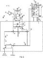
- FIGURE 1 is a schematic view of a cooling system 10 that employs a thermosyphon cooler 12 and a cooling tower 14.
- the cooling system 10 may be primarily located within a building 16 or area that is maintained at temperatures above freezing. However, certain components of cooling system 10, such as thermosyphon cooler 12 and cooling tower 14, may be located outside of building 16, for example, on the roof of building 16. Further, in other embodiments, cooling tower 14 may be located a distance away from building 16 or the process area and, in certain embodiments, may be located at ground level.
- Cooling system 10 includes a process heat exchanger 18 that may be used to transfer heat from a process loop 20 to a cooling system loop 22.
- process loop 20 may circulate a process fluid, such as refrigerant, steam, or other vapor to be condensed.
- process loop 20 may circulate compressed refrigerant vapor to be condensed from a water chiller.
- process loop 20 may circulate steam to be condensed from a steam turbine.
- process loop 20 may circulate a process fluid for an industrial process that may require cooling.
- Cooling system loop 22 may circulate a fluid to be cooled, such as water or a mixture of water and other components. As the cooling fluid flows through process heat exchanger 18, the cooling fluid may absorb heat from the process fluid. According to certain embodiments, an intermediate fluid, such as refrigerant may be used to transfer heat from the process fluid within process loop 20 to the cooling fluid within cooling system loop 22.
- process heat exchanger 18 may be a water cooled condenser that is part of a chiller that circulates a refrigerant to transfer heat from process loop 20 to cooling system loop 22. In these embodiments, the process fluid may flow through an evaporator of the chiller.
- the intermediate fluid may be omitted and the process heat exchanger 18 may be used to transfer heat directly from the process fluid to the cooling fluid.
- process heat exchanger 18 may be omitted and the cooling fluid within cooling system loop 22 may be circulated directly to the process to be cooled.
- cooling fluid may absorb heat from the process fluid. Accordingly heated cooling fluid may exit process heat exchanger 18 and may flow through cooling system loop 22 through a valve 24 to thermosyphon cooler 12.
- a pump may be included to circulate the cooling fluid to thermosyphon cooler 12 from valve 24. However, in other embodiments, the pump may be omitted.
- thermosyphon cooler 12 may include a shell and tube evaporator 76 and an air cooled condenser 78.
- a refrigerant loop 80 is employed to transfer heat from the cooling fluid flowing through shell and tube evaporator 76 to air cooled condenser 78.
- Heat may be rejected from thermosyphon cooler 12 through ambient air directed over air cooled condenser 78 by one or more fans 26 driven by one or more motors 28.
- motors 28 may incorporate variable speed drives (VSD's) that allow the speed of fans 26 to be adjusted to increase and decrease the amount of cooling provided by thermosyphon cooler 12.
- VSD's variable speed drives
- cooling tower 14 the cooling fluid may be cooled via evaporative cooling with ambient air.
- the cooling fluid may enter cooling tower 14 through nozzles 34 that direct the cooling fluid down through cooling tower 14 over a fill material 36, such as splash bars, sheet fill packs, or any other suitable surface.
- a fan 38 driven by a motor 40 may direct air up through cooling tower 14 so that the air mixes with the cooling fluid flowing through cooling tower 14 to promote evaporative cooling.
- fan 38 may be a centrifugal or axial fan driven by a VSD.
- fan 38 may be omitted and air movement within the cooling tower would be induced by natural convection.
- Cooling tower 14 may be a crossflow or a counterflow cooling tower. Further, although shown as an induced draft cooling tower, in other embodiments, cooling tower 14 may be a forced draft cooling tower.
- sump 42 is located within building 16, which, in certain embodiments, may inhibit freezing of the cooling fluid within sump 42.
- sump 42 may be an integral part of cooling tower 14 and may be located outside of building 16, as described further below with respect to FIGURE 4 .
- cooling fluid flows through cooling tower 14 and contacts ambient air, solids and other contaminants may become entrapped or entrained within the cooling fluid. Additional minerals, salts, and other contaminants may enter the cooling fluid with make-up water. As pure water is removed from the cooling fluid through evaporation, the concentration of such contaminants will increase within the cooling fluid. Accordingly, a portion of the cooling fluid, which may contain particulates, dissolved solids, and/or contaminants, may be removed as blowdown by opening a valve 46. A valve 44 also may be opened to direct makeup cooling fluid into sump 42 to account for losses in the cooling fluid due to blowdown and evaporation. The cooled cooling fluid from sump 42 may then be returned to process heat exchanger 18 via a pump 48 where the cooling fluid may again absorb heat from the process fluid circulating within process fluid loop 20.
- Cooling system 10 also includes a controller 50 that governs operation of cooling system 10.
- Controller 50 may receive input signals 52 from components, such as valves and sensors within system 10, in the form of analog and/or digital inputs as shown in FIGURE 8 . Based on the input signals, controller 50 may send output signals 54, such as analog and/or digital outputs shown in FIGURE 8 , to vary operation of cooling system 10. As described further below with respect to FIGURES 6 and 7 , controller 50 may use the input and output signals 52 and 54 to enable operation of thermosyphon cooler 12 whenever it is efficient to operate thermosyphon cooler 12 in addition to, or instead of cooling tower 14.
- controller 50 also may govern operation of a freeze protection system 56 included within cooling system 10.
- Freeze protection system 56 may include a differential pressure switch 58 that measures the pressure difference between the cooling fluid entering and exiting thermosyphon cooler 12 and a temperature sensor 57 that measures the temperature of the refrigerant within the shell side of evaporator 76.
- Controller 50 may use input signals 52 from differential pressure switch 58 to determine whether cooling fluid is flowing through thermosyphon cooler 12. If controller 50 detects that there is no cooling fluid flow based on input from differential pressure switch 58, controller 50 may initiate a low temperature protection mode of freeze protection system 56, which may inhibit freezing of the cooling fluid used within thermosyphon cooler 12.
- controller 50 may close a valve 97 to promote collection of the refrigerant within condenser 78.
- the lack of refrigerant flow to evaporator 76 may inhibit freezing of the cooling fluid within evaporator 76.
- Controller 50 also may turn on supplemental heat for evaporator 76 to provide an influx of heat to evaporator 76 to inhibit freezing of the cooling fluid included within evaporator 76.
- Controller 50 also may use input from temperature sensor 57 to govern operation of freeze protection system 56. For example, when controller 50 receives an input from temperature sensor 57 that indicates that the temperature within evaporator 76 is below a certain set point, controller 50 may initiate a freeze protection mode of freeze protection system 56, which may drain the cooling fluid from thermosyphon cooler 12 and may divert the flow of the cooling fluid around thermosyphon cooler 12. To drain the cooling fluid from thermosyphon cooler 12, controller 50 may open valves 60 and 62 to direct the cooling fluid to a drain line 64. As shown, drain line 64 may direct the cooling fluid to sump 42. However, in other embodiments, for example, where sump 42 is located outside of building 16, drain line 64 may be connected to a sewer or a collection reservoir.
- Controller 50 also may close valve 30 to direct cooling fluid exiting thermosyphon cooler 12 to drain line 64 through valve 62. Further, controller 50 may open a valve 66 to inject air into thermosyphon cooler 12 to facilitate drainage of the cooling fluid from thermosyphon cooler 12. According to certain embodiments, valve 66 may be designed to inject air into the evaporator tubes of thermosyphon cooler 12 to displace the cooling fluid from the evaporator tubes. To inhibit the flow of additional cooling fluid into thermosyphon cooler 12, controller 50 also may change the position of valve 24 to direct the cooling fluid from process heat exchanger 18 to bypass thermosyphon cooler 12 and flow directly to valve 32. According to certain embodiments, valves 60, 62, and 66 may be solenoid valves designed to fail in the open position, which, in the event of a power failure, may automatically enable freeze protection system 56.
- Cooling system 10 also may include temperature sensors 68, 70, 72, and 74 that may be used to detect temperatures used by controller 50 to govern operation of cooling system 10.
- temperature sensor 68 may detect the ambient air temperature
- temperature sensor 70 may detect the temperature of the cooling fluid exiting thermosyphon cooler 12
- temperature sensor 72 may detect the temperature of the cooling fluid exiting process heat exchanger 18
- temperature sensor 74 may detect the temperature of the cooling fluid entering process heat exchanger 18.
- Temperature sensors 68, 70, 72, and 74 may provide the temperatures to controller 50 in the form of input signals 52, which may be used to control operation of cooling system 10.
- controller 50 may use temperatures sensed by some, or all of the sensors 57, 68, 70, 72, and 74 to determine when to enable freeze protection system 56. For example, controller 50 may initiate the low temperature protection mode of freeze protection system 56 when there is no flow, as detected by differential pressure switch 58, and when the ambient temperature, as detected by sensor 68, is below an ambient temperature set point. In another example, controller 50 may disable a freeze protection mode of freeze protection system 56 when the temperature of the cooling fluid exiting thermosyphon cooler 12, as detected by sensor 70, is above an intermediate temperature set point.
- Controller 50 also may use temperatures sensed by some, or all of, the sensors 57, 68, 70, 72, and 74 to determine operating parameters of thermosyphon cooler 12.
- cooling system 10 may be designed to cool the cooling fluid entering process heat exchanger 18 to a specific temperature, which may be referred to as the cooling system temperature set point. If the temperature of the cooling fluid entering process heat exchanger 18, as detected by sensor 74, is above the cooling system temperature set point, controller 50 may provide output signals to motor 28 to increase the speed of the condenser fans 26. Similarly, if the temperature of the cooling fluid entering process heat exchanger 18, as detected by sensor 74, is below the cooling system temperature set point, controller 50 may provide output signals to motor 28 to decrease the speed of the condenser fans 26.
- Controller 50 also may use temperatures sensed by some, or all of the sensors 57, 68, 70, 72, and 74 to determine when to operate cooling tower 14. For example, if the temperature of the cooling fluid exiting thermosyphon 12, as detected by sensor 70, is equal to or below the cooling system temperature set point, controller 50 may provide an output signal to valve 32 to change the position of valve 32 so that the cooling fluid bypasses cooling tower 14 and proceeds directly to sump 42.
- thermosyphon cooler 12 may be capable of providing enough cooling capacity to achieve the cooling system temperature set point, and accordingly, cooling system 10 may be operated without employing cooling tower 14, which may reduce water consumption within cooling system 10.
- controller 50 also may use temperatures sensed by some, or all of the sensors 57, 68, 70, 72, and 74 to determine when to operate thermosyphon cooler 12. For example, controller 50 may use temperatures sensed by sensors 72 and 68 to determine the temperature difference between the cooling fluid exiting process heat exchanger 18 and the ambient air. Controller 50 may then use this temperature difference in conjunction with water and electricity rates to determine when it is economically and/or resource efficient to operate thermosyphon cooler 12.
- thermosyphon cooler 12 includes a shell and tube evaporator 76 and an air cooled condenser 78.
- Shell and tube evaporator 76 may receive heated cooling fluid from process heat exchanger 18 ( FIGURE 1 ) and may transfer heat from the cooling fluid to refrigerant flowing through the evaporator 76.
- the refrigerant may be an HFC or an HFO type refrigerant; however, in other embodiments, any suitable refrigerant may be employed.
- the heated refrigerant may be directed through piping of refrigerant loop 80 to condenser 78, where the refrigerant may be cooled by ambient air directed through condenser 78 by fans 26.
- the cooled refrigerant may then be returned to evaporator 76 through refrigerant loop 80.
- evaporator 76 and condenser 78 may be included within a common frame 82 that allows thermosyphon cooler 12 to be sold as a single integrated package.
- evaporator 76 and condenser 78 may be disposed within separate frames or may be installed within separate parts of cooling system 10.
- evaporator 76 as a shell and tube evaporator
- other embodiments may include another type of evaporator, such as a plate evaporator design, in lieu of a shell and tube design.
- Shell and tube evaporator 76 may include a shell 84 that contains the refrigerant as the refrigerant flows through evaporator 76.
- Shell 84 also may house tubes 86 that circulate the cooling fluid through evaporator 76.
- the cooling fluid may enter tubes 86 through an inlet 87 and may exit tubes 86 through an outlet 87. As the cooling fluid flows through tubes 86, the cooling fluid may transfer heat to the refrigerant flowing within shell 84.
- the heated refrigerant As the refrigerant absorbs heat, the heated refrigerant, which is more buoyant than the cooler refrigerant, may be drawn by natural convection through pipes 80 into condenser 78, which is at a lower temperature than evaporator 76.
- the heated refrigerant may then flow through a heat transfer coil 88 included within condenser 78 and fans 26 may draw environmental air over coil 88 to cool the refrigerant flowing within coil 88.
- the cooled refrigerant may then return by gravity to shell 84 where the refrigerant may again absorb heat from the cooling fluid within tubes 86.
- condenser 78 may be disposed at a height 90 above evaporator 76 to promote the return of cooled refrigerant to evaporator 76.
- Condenser 78, evaporator 76, and piping of refrigerant loop 80 may be sized to minimize the pressure drop within thermosyphon cooler 12, thereby allowing a lower height 90 to be employed to return refrigerant from condenser 78 to evaporator 76 through natural convection.
- height 90 may be less than approximately 10 to 12 feet to allow thermosyphon cooler 12 to be shipped as a single integrated package on a conventional road truck.
- height 90 may be any suitable height.
- evaporator 76 also may be disposed at an angle to promote drainage of cooling fluid from evaporator 76. According to certain embodiments, evaporator 76 may be tilted at an angle of approximately 5 degrees with respect to horizontal.
- Evaporator 76 may be designed as a cleanable evaporator where the interior of tubes 86 may be accessed for cleaning to remove contaminant buildup from particulates and/or dissolved solids that enter tubes 86 with the cooling fluid.
- the cooling fluid may absorb solids from the environmental air that contacts the cooling fluid in cooling tower 14.
- evaporator 76 may include an access cover 92 that may be removed to expose openings into tubes 86.
- evaporator 76 may include a removable head section 94 that may allow access to tubes 86 for cleaning.
- evaporator 76 also may include a sensor 95, such as an optical sensor, designed to detect the level of the cooling fluid within evaporator 76.
- sensor 95 may be used in conjunction with freeze protection system 56 to ensure that the cooling fluid has been drained from evaporator 76 when the freeze protection mode of freeze protection system 56 has been enabled.
- thermosyphon cooler 12 includes a valve 97 disposed within piping of refrigerant loop 80 to stop the flow of refrigerant through refrigerant loop 80.
- valve 97 may be closed by controller 50 upon detecting a condition, such as a low ambient temperature, low evaporator temperature, for example, measured at temperature sensor 95, and/or no flow within thermosyphon cooler 12, that may produce freezing.
- a condition such as a low ambient temperature, low evaporator temperature, for example, measured at temperature sensor 95, and/or no flow within thermosyphon cooler 12, that may produce freezing.
- valve 97 may promote collection of the refrigerant within coil 88 of condenser 78, which may inhibit circulation of the refrigerant within circuit 80 and prohibit circulation of refrigerant to evaporator 76.
- evaporator 76 also may incorporate supplemental heating and/or insulation, to provide an influx of heat to evaporator 76 upon detecting a potential freeze condition.
- FIGURE 4 depicts another embodiment of the cooling system 10 that includes open loop cooling tower 14 and thermosyphon cooler 12.
- the embodiment of cooling system 10 shown in FIGURE 4 is generally similar to the embodiment of cooling system 10 described above with respect to FIGURE 1 .
- the cooling tower 14 shown in FIGURE 4 includes an integrated sump 42 rather than a sump that is disposed within building 16, as shown in FIGURE 1 .
- thermosyphon cooler 12 includes freeze protection system 56, which may operate as described above with respect to FIGURE 1 .
- drain line 64 may be directed to a sewer or collection reservoir, rather than to sump 42.
- the cooling fluid exiting thermosyphon cooler 12 may flow through valve 32 to cooling tower 14.
- the cooling fluid may be directed over fill material 36 by nozzles 34 and may collect within sump 42, which may be located in the lower portion of cooling tower 14.
- Valve 44 may be opened to direct makeup cooling fluid into sump 42 to account for losses in the cooling fluid due to blowdown and evaporation.
- Valve 46 also may be opened to remove blowdown from cooling tower 14.
- the cooled cooling fluid from sump 42 may then be returned to process heat exchanger 18 via pump 48.
- process heat exchanger 18 the cooling fluid may again absorb heat from the process fluid circulating within process fluid loop 20.
- thermosyphon cooler 12 may be employed in a cooling system 10 that includes an open loop cooling tower where environmental air may directly contact the cooling fluid flowing through cooling system 10.
- thermosyphon cooler 12 may be employed within a closed circuit cooling tower as shown in FIGURE 5 . Closed loop cooling towers may be particularly useful in systems where it may be desirable to reduce contaminants in the cooling fluid.
- cooling system 10 in FIGURE 5 may be generally similar to the cooling system described above with respect to FIGURE 1 . However, rather than allowing the cooling fluid within cooling system loop 22 to be directly exposed to the ambient air within cooling tower 14 as in FIGURE 1 , cooling system 10 in FIGURE 5 is isolated from contacting ambient air by employing closed circuit cooling tower 91 in lieu of cooling tower 14. Within closed circuit cooling tower 91, the cooling fluid flowing through cooling system loop 22 may be cooled through closed circuit cooling tower cooling coil 98 which may transfer heat to a spray water loop 102 which is integral to closed circuit cooling tower 91.
- the spray water circulating within spray water loop 93 may be cooled via evaporative cooling with ambient air, thus enabling the cooling fluid flowing through cooling system loop 22 from being exposed to the airborne and makeup water borne contaminants normally associated with open cooling system loops.
- the spray water loop may include nozzles 34 which direct the spray water over the closed circuit cooling tower cooling coil 98, a sump 42 to collect the spray water, spray water piping 99, and a spray water pump 101.
- a fan 38 driven by a motor 40 may direct air up through closed circuit cooling tower 91 to promote evaporative cooling of the spray water.
- a blowdown valve 46 may be used to remove contaminants from spray water loop 93 and makeup water valve 44 may be used to direct makeup spray water into sump 42 to account for losses in spray water due to blowdown and evaporation.
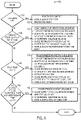
- FIGURE 6 depicts a method 100 that may be employed to govern operation of a cooling system 10 that includes an open loop cooling tower, as shown in FIGURES 1 and 4 , or a closed loop cooling tower, as shown in FIGURE 5 .
- Method 100 may begin by determining (block 102) whether cooling system 10 is beginning operation. For example, cooling system 10 may begin operation upon startup of process heat exchanger 18. If cooling system 10 is beginning operation, controller 50 may initiate (block 103) a freeze protection mode of freeze protection system 56. To initiate the freeze protection mode, controller 50 may position valve 24 to direct the cooling fluid to bypass thermosyphon cooler 12. Controller 50 also may leave valves 60, 62, and 66 in the open position. Further, controller 50 may close valve 97 to stop the flow of refrigerant within refrigerant loop 80 of thermosyphon cooler 12.
- controller 50 may determine (block 104) whether to initiate a low temperature protection mode of freeze protection system 56. For example, controller 50 may receive the ambient temperature as an input from temperature sensor 68 and may determine whether the ambient temperature is below an ambient temperature set point, which, in certain embodiments, may be 36°F. However, in other embodiments, the ambient temperature set point may vary. If the ambient temperature is below the ambient temperature set point, controller 50 may then determine if there is flow through thermosyphon cooler 12. For example, controller 50 may detect flow through thermosyphon cooler 12 using differential pressure switch 58.
- controller 50 may initiate (block 105) the low temperature protection mode of freeze protection system 56.
- the low temperature protection mode may allow the cooling fluid to be retained within thermosyphon cooler 12 during relatively short periods of low ambient temperatures and/or during relatively short periods of shutdown of cooling system 10. For example, low temperature protection mode may be initiated when cooling system 10 is shutdown overnight when there is no cooling demand from process heat exchanger 18.
- controller 50 may adjust operation of cooling system 10 to protect the cooling fluid within thermosyphon cooler 12 from freezing. For example, controller 50 may turn off the thermosyphon cooler fans 26. Controller 50 also may ensure that valves 24 and 30 are open to allow the cooling fluid to flow through thermosyphon cooler 12. Further, controller 50 may close valve 97 to stop the flow of refrigerant through refrigerant loop 80. Closing valve 97 may allow the refrigerant to collect within condenser 78, which may inhibit freezing of the cooling fluid within evaporator 76. Controller 50 also may turn on the supplemental heat for evaporator 76, which may provide heat to evaporator 76 to inhibit freezing of the cooling fluid contained within evaporator 76.
- controller 50 may then determine (block 106) whether the evaporator temperature is below an evaporator temperature set point. For example, controller 50 may receive the evaporator temperature as an input from temperature sensor 57, which may indicate the temperature of the refrigerant within the shell side of evaporator 76. According to certain embodiment, the evaporator temperature set point may be 33°F (0.56°C). However, in other embodiments, the evaporator temperature set point may vary.
- controller 50 may initiate (block 108) the freeze protection mode of freeze protection system 56.
- controller 50 may adjust operation of cooling system 10 so that the cooling fluid bypasses thermosyphon cooler 12.
- controller 50 may turn off the thermosyphon cooler fans 26 and may divert water away from thermosyphon cooler 12 using valve 24.
- Controller 50 also may position valve 32 to direct the cooling fluid exiting thermosyphon cooler 12 directly to sump 42. After the cooling fluid has drained from thermosyphon cooler 12, controller 50 may position valve 32 to allow the cooling fluid to flow through cooling tower 14, where the cooling fluid may be cooled by evaporative cooling.
- controller 50 also may drain cooling fluid from thermosyphon cooler 12.
- controller 50 may close valve 30 and open valves 60 and 62 to direct the cooling fluid within thermosyphon cooler 12 to drain line 64.
- Controller 50 also may open valve 66 to inject air into thermosyphon cooler 12 to further promote drainage of the cooling fluid from thermosyphon cooler 12.
- draining the cooling fluid from thermosyphon cooler 12 in freeze protection mode may protect tubes 86 from damage due to expansion and/or freezing of the cooling fluid.
- controller 50 may then determine (block 110) whether the freeze protection mode should be disabled. First, controller 50 may determine whether freeze protection mode is currently enabled, for example, based on the positions of valves 24, 60, 62, 66, and 30. If freeze protection mode is currently enabled, controller 50 may then determine whether the intermediate temperature (i.e. the temperature of the cooling fluid exiting thermosyphon cooler 12), as measured by temperature sensor 70, is above an intermediate temperature set point, which, in certain embodiments, may be approximately 50°F (10°C). However, in other embodiments, the intermediate temperature set point may vary.
- the intermediate temperature i.e. the temperature of the cooling fluid exiting thermosyphon cooler 12
- controller 50 may allow cooling system 10 to continue operating in the freeze protection mode. However, if the intermediate temperature is above the intermediate temperature set point, controller 50 may initiate (block 112) a freeze restart sequence to allow the cooling fluid to flow through thermosyphon cooler 12. In particular, controller 50 may close drain valves 60 and 62 and also may close vent valve 66. Further, controller 50 may adjust the positions of valves 24 and 30 to allow the cooling fluid to flow through thermosyphon cooler 12. Accordingly, cooling system 10 may now be operating in a process cooling mode where the cooling fluid flows through thermosyphon cooler 12 to be cooled by the ambient air.
- method 100 may then continue by determining (block 114) whether cooling system 10 is operating in a process cooling mode.
- cooling system 10 In the process cooling mode, cooling system 10 may be set so that the cooling fluid is directed through both thermosyphon cooler 12 and cooling tower 14.
- controller 50 may detect operation in the process cooling mode based on inputs from motors 28 and 40 and valves 24 and 32. If controller 50 detects that cooling system 10 is not operating in the process cooling mode, controller 50 may leave cooling system 10 operating in its current mode. For example, if cooling system 10 is not operating in the process cooling mode, cooling system 10 may be operating in the freeze protection mode or in the low temperature mode.
- controller 50 then performs (block 116) calculations that are used to determine (block 118) whether cooling with thermosyphon cooler 12 should be enabled.
- the controller 50 calculates the thermosyphon economic power consumption limit (TEPCL).
- TEPCL thermosyphon economic power consumption limit
- the TEPCL is the maximum kilowatts of electricity that should be used by condenser fans 26 per degree of cooling fluid temperature drop achieved by thermosyphon cooler 12 to ensure that the avoided water costs are greater than the incremental electricity costs used to operate thermosyphon cooler 12.
- the TEPCL is calculated using the cost of water and/or the cost of electricity as inputs. Other inputs may include ambient wet bulb and dry bulb temperatures, cooling tower water usage, the cost of waste water, the cost of water treatment, and/or cooling tower fan power consumption, among others.
- the costs of water and electricity may be input by an operator or may be obtained by controller 50 over a network connection. Using the water and electricity rates, controller 50 may calculate the TEPCL as the maximum kilowatts that should be used by the condenser fan motors 28 per degree of cooling as measured by the temperature difference between the temperature of the cooling fluid exiting process heat exchange 18, as measured by sensor 72, and the temperature of the cooling fluid exiting thermosyphon cooler 12 (i.e. the intermediate temperature), as measured by sensor 70.
- the TEPCL may be used to calculate a thermosyphon start threshold (TST).
- TST thermosyphon start threshold
- the thermosyphon start threshold may be the minimum temperature difference that should exist between the temperature of the cooling fluid exiting process heat exchanger 18, as measured by temperature sensor 72, and the ambient air temperature, as measured by temperature sensor 68, to allow the thermosyphon cooler 12 to be operated at an economic power consumption level below the TEPCL when condenser fans 26 are operated at a low fan speed.
- Controller 50 may then use the calculated TST to determine (block 118) whether the actual temperature difference between the cooling fluid exiting process heat exchanger 18 and the ambient air temperature is greater than the TST. For example, controller 50 may calculate the actual temperature difference based on the temperatures received from sensors 70 and 68. If the actual temperature difference is below the TST, controller 50 may disable (block 120) operation of thermosyphon cooler 12. For example, controller 50 may position valve 24 so that the cooling fluid bypasses thermosyphon cooler 12. Further, in certain embodiments, controller 50 may turn off condenser fans 26.
- controller 50 also may determine whether an ambient temperature is above a high temperature set point. For example, controller 50 may receive an input from temperature sensor 68 that indicates the ambient temperature. If the ambient temperature is above the high temperature set point, controller 50 may disable (block 120) operation of thermosyphon cooler 12.
- the high temperature set point may be the ambient temperature above which heat would be added to the cooling fluid flowing through thermosyphon cooler 12. Accordingly, in certain embodiments, the high temperature set point may depend on the temperature of the cooling fluid exiting process heat exchanger 18, which may be detected by temperature sensor 72. In situations where the ambient temperature is approximately equal to or higher than the temperature of the cooling fluid exiting process heat exchanger 18, it may be desirable to bypass thermosyphon cooler 12 to avoid adding heat from the ambient air to the cooling fluid.
- controller 50 may enable (block 122) operation of thermosyphon cooler 12. For example, controller 50 may position valve 24 to allow the cooling fluid to flow through thermosyphon cooler 12. Accordingly, the cooling fluid may flow through thermosyphon 12 where the fluid may be cooled by the ambient air.
- controller 50 may then adjust operation of fans 26 to vary the amount of cooling provided by thermosyphon cooler 12. According to certain embodiments, the operation of fans 26 may be adjusted to minimize consumption of electricity while still providing the desired amount of cooling. For example, controller 50 may determine (block 124) whether the intermediate temperature, as measured by temperature sensor 70, is below the cooling system temperature set point. When the intermediate temperature is at or below the cooling system temperature set point, which is the desired temperature of the cooling fluid entering process heat exchanger 18, thermosyphon cooler 12 may be capable of providing enough cooling to achieve the cooling system temperature set point, without additional cooling from cooling tower 14. Further when the intermediate temperature is below the cooling system temperature set point, thermosyphon 12 may be currently overcooling the cooling fluid, and accordingly, the speed of condenser fans 26 may be reduced.
- controller 50 may then determine (block 126) whether the condenser fans are operating at the minimum speed. If the condenser fans are operating at the minimum speed, controller 50 may turn off (block 128) the condenser fans. In these embodiments, the temperature of the ambient air may be low enough to cool the cooling fluid to the cooling system temperature set point without using electricity to operate the fans. In this mode of operation, thermosyphon cooler 12 may be operated without consuming electricity. On the other hand, if controller 50 determines (block 126) that the fans are not operating at the minimum fan speed, controller 50 may decrease (block 130) the fan speed. Reducing the fan speed may reduce the amount of electricity consumed by thermosyphon cooler 12.
- thermosyphon cooler 12 may not be currently providing enough cooling to achieve the cooling system temperature set point. Accordingly, controller 50 may determine whether it should increase the cooling capacity of thermosyphon cooler 12 by adjusting the speed of the condenser fans. First, controller 50 may determine (block 132) whether the condenser fans are operational. If the fans are operational, controller 50 may then determine (block 134) whether the fans are operating in an economically efficient manner. According to certain embodiments, controller 134 may calculate the current thermosyphon economic power consumption (TEPC) used by thermosyphon cooler 12.
- TEPC thermosyphon economic power consumption
- controller 50 may calculate the current kilowatts being used by motor 28 and may divide these kilowatts by the temperature difference between the temperature of the cooling fluid exiting process heat exchanger 18, as measured by temperature sensor 72 and temperature of the cooling fluid exiting thermosyphon cooler 12, as measured by temperature sensor 70.
- the controller 50 may then compare the actual TEPC to the TEPCL. If the actual TEPC is above the TEPCL, controller 50 may then decrease (block 135) the fan speed. Decreasing the fan speed may reduce the amount of cooling provided by thermosyphon cooler 12 and accordingly, more cooling may be provided by cooling tower 14. In these instances, controller 50 may increase the speed of cooling tower fan 38 to provide additional cooling capacity. On the other hand, if the TEPC is below the TEPCL, controller 50 may increase (block 136) the speed of the condenser fans to increase the amount of cooling provided by thermosyphon cooler 12. Further, if controller 50 determines (block 132) that the fans are not on, controller 50 may turn on (block 138) the fans to the minimum fan speed. Controller 50 may then again determine (block 124) whether the intermediate temperature is below the cooling system temperature set point and may then adjust operation of the condenser fans as described above with respect to blocks 126 to 138.
- Controller 50 may then use the calculated TST to determine (block 118) whether the actual temperature difference between the cooling fluid exiting process heat exchanger 18 and the ambient air temperature is greater than the TST. For example, controller 50 may calculate the actual temperature difference based on the temperatures received from sensors 72 and 68. If the actual temperature difference is below the TST, controller 50 may disable (block 120) operation of thermosyphon cooler 12. For example, controller 50 may position valve 24 so that the cooling fluid bypasses thermosyphon cooler 12. Further, in certain embodiments, controller 50 may turn off condenser fans 26.
- FIGURE 8 depicts various input and outputs that may be used by controller 50 to govern operation of cooling system 10.
- the input and outputs may be analog and/ or digital outputs and may be used by controller 50 to enable the freeze protection system 56 and to govern operation of thermosyphon cooler 12 and cooling tower 14.
- the inputs and outputs shown in FIGURE 7 may be employed by controller 50 to determine when to direct the cooling fluid through thermosyphon cooler 12, through cooling tower 14, or through both thermosyphon cooler 12 and cooling tower 14.
- FIGURES 6 and 7 describe method 100 in the context of a thermosyphon cooler, in other examples not forming part of the present invention, portions of method 100 may be employed to control cooling systems with other types of dry heat rejection systems, such as an air cooled condenser used in parallel with an evaporative condenser in a system circulating refrigerant directly to the heat rejection devices.
- dry heat rejection systems such as an air cooled condenser used in parallel with an evaporative condenser in a system circulating refrigerant directly to the heat rejection devices.
- FIGURES 6 and 7 describe method 100 in the context of a thermosyphon cooler, in other examples not forming part of the present invention, portions of method 100 may be employed to control cooling systems with other types of dry heat rejection systems, such as dry coolers used in conjunction with a freeze protectant coolant.
- FIGURE 9 depicts another example of cooling system 10, which includes a dry cooler 142 and a heat exchanger 143.
- dry cooler 142 may be similar to the air cooled condenser 78 employed within thermosyphon cooler 12.
- any suitable air cooled condenser or other type of dry heat rejection device may be used.
- the term "dry heat rejection device” may refer to a heat transfer device that does not employ wet or evaporative cooling.
- heat exchanger 143 may be similar to the evaporator 76 employed in the thermosyphon cooler 12.
- any suitable type of heat exchanger such as a plate heat exchanger, may be employed.
- cooling system 10 includes a dry heat rejection system that includes heat exchanger 143, dry cooler 142, a freeze protectant coolant loop, such as a glycol or brine loop 138, and a pump 140.
- the cooling fluid from process heat exchanger 18 may flow through heat exchanger 143, where the cooling fluid may transfer heat to the freeze protectant coolant, such as glycol or brine, flowing through heat exchanger 143.
- the cooling fluid may then exit heat exchanger 143 and flow to cooling tower 14 where the cooling fluid may be further cooled as described above with respect to FIGURE 1 .
- heat exchanger 143 is a shell and tube heat exchanger
- the cooling fluid may flow through the tubes of heat exchanger 143 while freeze protectant coolant, such as a glycol or brine, flows through the shell side of heat exchanger 143.
- the heated freeze protectant coolant from heat exchanger 143 may flow through coolant loop 138 to dry cooler 142 via pump 140.
- pump 140 may be driven by one or more motors.
- the freeze protectant coolant may be cooled by air that is directed through dry cooler 142 by fans 26. The cooled coolant may then exit dry cooler 142 and return to heat exchanger 143 where the coolant may again absorb heat from the cooling fluid flowing through heat exchanger 143.
- the cooling fluid may be contained within building 16 and may not be exposed to the ambient air. Accordingly, a freeze protection system may not be employed because the cooling system may be protected from low ambient temperatures by building 16. Accordingly, blocks 102 to 112 of method 100 ( FIGURE 6 ) may be omitted when operating the embodiment of the cooling system shown in FIGURE 9 . However, as shown in FIGURE 10 , a method 146 that is similar to blocks 114 to 138 of FIGURE 7 may be employed to operate the dry heat rejection system shown in FIGURE 9 .
- method 146 may begin by detecting (block 148) that cooling system 10 is operating in a process cooling mode.
- controller 50 may detect operation in the process cooling mode based on the positions of valves 24 and 32. If controller 50 detects that the system is operating in a process cooling mode, controller 50 may then calculate (block 150) the dry heat rejection economic power consumption limit (DEPCL).
- DEPCL dry heat rejection economic power consumption limit
- the DEPCL may be similar to the TEPCL described above with respect to FIGURES 5 to 7 .
- the DEPCL may be the maximum kilowatts of electricity used by the dry heat rejection system per degree of cooling fluid temperature drop achieved by the dry heat rejection system to ensure that the avoided water costs are greater than the incremental electricity costs used to operate the dry heat rejection system.
- the electricity costs may be based on the electrical consumption of motor 28 used to drive fans 26, as well as the electricity used by the motor that drives pump 140.
- Controller 50 may then calculate (block 152) the dry heat rejection system start threshold (DST).
- the DST may be similar to the TST described above with respect to FIGURES 5 to 7 .
- the DST may be the minimum temperature difference that should exist between the temperature of the cooling fluid exiting the process heat exchanger, as measured by sensor 72, and the ambient temperature, as measured by temperature sensor 68, that is known to enable an actual power consumption of the dry heat rejection system, which is below the DEPCL.
- Controller 50 may then use the calculated DST to determine (block 154) whether the actual temperature difference between the cooling fluid exiting process heat exchanger 18 and the ambient air is greater than the DST. If the actual temperature difference is below the DST, controller 50 may disable (block 156) operation of the dry heat rejection system. For example, controller 50 may position valve 24 to direct the cooling fluid to bypass heat exchanger 143 and flow directly through valve 32 to cooling tower 14. Further, in certain embodiments, controller 50 may turn off fans 26 and pump 140.
- controller 50 may enable (block 158) the dry heat rejection system. For example, controller 50 may adjust valve 24 to direct the cooling fluid through heat exchanger 143 to transfer heat from the cooling fluid to the freeze protectant coolant that flows through dry cooler 142. Further, controller 50 may turn on fans 26 and pump 140. Moreover, while the dry heat rejection system is operating, controller 50 may govern operation of fans 26 as described above in FIGURE 6 with respect to blocks 124 to 138.
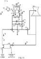
- FIGURE 11 depicts another embodiment of cooling system 10 that includes thermosyphon cooler 12 and an open loop cooling tower 160, which is a natural draft hyperbolic cooling tower.
- a steam condenser 162 may be used to transfer heat from steam from a turbine to cooling system loop 22.
- the cooling system 10 may be used to provide cooling for a power plant.
- the cooling system shown in FIGURE 11 may operate generally similar to the cooling system described above with respect to FIGURE 1 , and method 100 may be employed to operate the cooling system, as described above with respect to FIGURES 6 and 7 .
Landscapes
- Engineering & Computer Science (AREA)
- Mechanical Engineering (AREA)
- General Engineering & Computer Science (AREA)
- Physics & Mathematics (AREA)
- Thermal Sciences (AREA)
- Sustainable Development (AREA)
- Life Sciences & Earth Sciences (AREA)
- Combustion & Propulsion (AREA)
- Chemical & Material Sciences (AREA)
- Cooling Or The Like Of Electrical Apparatus (AREA)
- Devices That Are Associated With Refrigeration Equipment (AREA)
- Other Air-Conditioning Systems (AREA)
- Details Of Measuring And Other Instruments (AREA)
- Greenhouses (AREA)
- Heat-Exchange Devices With Radiators And Conduit Assemblies (AREA)
- Separation By Low-Temperature Treatments (AREA)
- Air Conditioning Control Device (AREA)
Claims (11)
- Kühlsystem (10), umfassend:- einen Wärmeumlaufkühler (12), der dazu konfiguriert ist, Wärme von einem Kühlfluid durch Trockenkühlung an Umgebungsluft zu übertragen, und umfassend:- einen ersten Wärmetauscher (76), der so konfiguriert ist, dass er Wärme von dem Kühlfluid auf ein Kältemittel überträgt, das durch den ersten Wärmetauscher (76) zirkuliert;- einen zweiten Wärmetauscher (78), der dazu konfiguriert ist, Wärme von dem Kältemittel an die Umgebungsluft zu übertragen; und- Rohrleitungen (80), die so bemessen sind, dass sie das Kältemittel zwischen dem ersten Wärmetauscher (76) und dem zweiten Wärmetauscher (78) basierend auf natürlicher Konvektion zirkulieren lassen, wobei das Kühlfluid und das Kältemittel fluidmäßig voneinander getrennt sind;- einen Kühlturm (14), der in Bezug auf das Kühlfluid stromabwärts des Wärmeumlaufkühlers (12) angeordnet ist und so konfiguriert ist, dass er Wärme von dem Kühlfluid durch Verdunstungskühlung an Umgebungsluft überträgt; und- eine Steuerung (50), die einen Eingang zum Erhalten von Wasserkosten oder Stromkosten oder beiden durch einen Betreiber oder über eine Netzwerkverbindung umfasst, wobei die Steuerung (50) so konfiguriert ist, dass sie auf der Grundlage der erhaltenen Wasserkosten oder der erhaltenen Stromkosten oder beider einen Grenzwert für den wirtschaftlichen Stromverbrauch des Wärmeumlaufs, TEPCL, bestimmt, unter dem es kosteneffektiv ist, den Wärmeumlaufkühler (12) zu betreiben, wobei die Steuerung (50) ferner dazu konfiguriert ist, basierend auf dem TEPCL-Wert zu bestimmen, ob der Betrieb des Wärmeumlaufkühlers (12) aktiviert oder deaktiviert werden sollte, und den Betrieb des Wärmeumlaufkühlers (12) basierend darauf zu steuern; und- ein Ventilsystem (24, 60, 62, 66, 97), das betriebsfähig mit der Steuerung (50) gekoppelt ist, und wobei die Steuerung (50) so konfiguriert ist, dass sie das Ventilsystem (24, 60, 62, 66, 97) so einstellt, dass es den Kältemittelfluss innerhalb der Rohrleitung (80) als Reaktion auf das Erfassen einer Kältemitteltemperatur stoppt, die unter einem Verdampfertemperatursollwert liegt.
- Kühlsystem (10) nach Anspruch 1,
wobei der Wärmeumlaufkühler (12) ohne mechanische Umwälzeinrichtung arbeitet. - Kühlsystem (10) nach Anspruch 1,
wobei die Steuerung (50) dazu konfiguriert ist, das Ventilsystem (60, 62) einzustellen, um das Kühlfluid aus dem Wärmeumlaufkühler (12) als Reaktion auf das Erfassen einer unter einem Temperatursollwert liegenden Temperatur des Kühlmittels innerhalb des ersten Wärmetauschers (76) abzulassen. - Kühlsystem (10) nach Anspruch 1,- wobei der erste Wärmetauscher ein Rohrbündelverdampfer (76) ist, der einen entfernbaren Abschnitt zum Reinigen von Rohren des Rohrbündelverdampfers (76) umfasst; und- wobei der zweite Wärmetauscher ein luftgekühlter Kondensator (78) ist.
- Kühlsystem (10) nach Anspruch 4,
wobei der Wärmeumlaufkühler (12) einen einzelnen Rahmen (82) umfasst, der den Rohrbündelverdampfer (76), die Rohrleitung (80) und den luftgekühlten Kondensator (78) enthält. - Kühlsystem (10) nach Anspruch 4,
wobei der abnehmbare Abschnitt eine Zugangsabdeckung (92) umfasst, die von einem Kopfende des Rohrbündelverdampfers (76) oder einem abnehmbaren Kopfende des Rohrbündelverdampfers (76) abnehmbar ist. - Kühlsystem (10) nach Anspruch 4,
umfassend ein Ventil (97), das mit der Rohrleitung (80) gekoppelt ist, um selektiv die Rückführung des Kühlmittels zu dem Rohrbündelverdampfer (76) von dem luftgekühlten Kondensator (78) zu blockieren. - Computerimplementiertes Verfahren zum Betreiben eines Kühlsystems (10) nach Anspruch 1, wobei das Verfahren Folgendes umfasst- Erhalten von Wasserkosten oder Stromkosten oder beidem durch eine Bedienereingabe oder über eine Netzwerkverbindung;- Bestimmen eines Grenzwerts für den wirtschaftlichen Stromverbrauch des Wärmeumlaufs, TEPCL, unterhalb dessen es kosteneffektiv ist, einen Wärmeumlaufkühler (12) zu betreiben, wobei der TEPCL-Wert basierend auf den erhaltenen Wasserkosten oder den erhaltenen Stromkosten oder beiden bestimmt wird;- Bestimmen, unter Verwendung des TEPCL-Werts, einer gewünschten Temperaturdifferenz zwischen einer ersten Temperatur des Kühlfluids, das einen durch das Kühlsystem (10) gekühlten Prozesswärmetauscher (18) verlässt, und einer Umgebungstemperatur;- Ermöglichen des Betriebs des Wärmeumlaufkühlers (12) als Reaktion auf das Erfassen, dass eine erfasste Temperaturdifferenz zwischen der ersten Temperatur und der Umgebungstemperatur größer als die gewünschte Temperaturdifferenz (TST) ist.
- Verfahren nach Anspruch 8,
umfassend das Berechnen eines tatsächlichen Energieverbrauchs des Wärmeumlaufkühlers (12) und das Anpassen einer Drehzahl eines oder mehrerer Lüfter (26) des Wärmeumlaufkühlers (12) basierend auf dem tatsächlichen Energieverbrauch des Wärmeumlaufkühlers (12). - Verfahren nach Anspruch 8,
umfassend das Aktivieren eines Gefrierschutzmodus als Reaktion auf das Erfassen einer Kältemitteltemperatur unter einem Gefrierschutztemperatur-Sollwert, wobei das Aktivieren eines Gefrierschutzmodus Folgendes umfasst:- Einstellen einer Position eines oder mehrerer Ventile (24, 60, 62, 66, 97), um ein Kühlfluid aus dem Wärmeumlaufkühler (12) abzulassen; oder- Öffnen eines Ventils (24, 60, 62, 66, 97), um Umgebungsluft in den Wärmeumlaufkühler (12) einzublasen, um ein Kühlfluid aus dem Wärmeumlaufkühler (12) abzulassen. - Verfahren nach Anspruch 8, umfassend:- Erfassen einer Zwischentemperatur eines Kühlfluids, das den Wärmeumlaufkühler (12) verlässt; und- Ermöglichen des Betriebs eines Kühlturms (14) als Reaktion auf das Erfassen, dass die Zwischentemperatur größer als ein Temperatursollwert für das in den Prozesswärmetauscher eintretende Kühlfluid ist.
Applications Claiming Priority (2)
| Application Number | Priority Date | Filing Date | Title |
|---|---|---|---|
| US34908010P | 2010-05-27 | 2010-05-27 | |
| PCT/US2010/042737 WO2011149487A2 (en) | 2010-05-27 | 2010-07-21 | Thermosyphon coolers for cooling systems with cooling towers |
Publications (2)
| Publication Number | Publication Date |
|---|---|
| EP2577205A2 EP2577205A2 (de) | 2013-04-10 |
| EP2577205B1 true EP2577205B1 (de) | 2023-01-04 |
Family
ID=43501029
Family Applications (1)
| Application Number | Title | Priority Date | Filing Date |
|---|---|---|---|
| EP10737203.9A Active EP2577205B1 (de) | 2010-05-27 | 2010-07-21 | Kühlsystem umfassend wärmeumlaufkühler und kühlturm und verfahren zum betrieb solch eines kühlsystems |
Country Status (11)
| Country | Link |
|---|---|
| US (4) | US10451351B2 (de) |
| EP (1) | EP2577205B1 (de) |
| JP (1) | JP5800894B2 (de) |
| KR (4) | KR20130031300A (de) |
| CN (2) | CN110118493A (de) |
| AU (1) | AU2010354078B2 (de) |
| BR (1) | BR112012030204B1 (de) |
| DK (1) | DK2577205T3 (de) |
| FI (1) | FI2577205T3 (de) |
| WO (1) | WO2011149487A2 (de) |
| ZA (1) | ZA201208280B (de) |
Families Citing this family (59)
| Publication number | Priority date | Publication date | Assignee | Title |
|---|---|---|---|---|
| PL2601105T3 (pl) * | 2010-08-06 | 2018-03-30 | Hospira Australia Pty Ltd | Sposób i system przygotowania fiolki |
| US20120234263A1 (en) * | 2011-03-18 | 2012-09-20 | Uop Llc | Processes and systems for generating steam from multiple hot process streams |
| JP2015514957A (ja) * | 2012-04-25 | 2015-05-21 | ビーエーエスエフ ソシエタス・ヨーロピアBasf Se | 二次回路内の冷媒の供給方法 |
| US9638435B2 (en) * | 2013-04-18 | 2017-05-02 | Level 3 Communications, Llc | Systems and methods for optimizing the efficiency of HVAC systems |
| US9784460B2 (en) * | 2013-08-01 | 2017-10-10 | Nautilus Data Technologies, Inc. | Data center facility and process that utilizes a closed-looped heat management system |
| DE112014004840A5 (de) * | 2013-10-22 | 2016-07-07 | Güntner Gmbh & Co. Kg | Ansteuereinheit für einen Wärmeaustauscher, Wärmeaustauscher und ein Verfahren zur Regelung eines Wärmeaustauschers |
| US9410254B2 (en) * | 2013-10-23 | 2016-08-09 | Najwa H. Samrgandi | HHO system, high production of hydrogen gas |
| US10132577B2 (en) * | 2014-01-20 | 2018-11-20 | Baltimore Aircoil Company, Inc. | Adiabatic refrigerant condenser controls system |
| CN104048550B (zh) * | 2014-05-29 | 2015-12-09 | 上海电力学院 | 一种自然通风冷却塔雨区引风聚流虹吸式排放装置 |
| CN105806091B (zh) * | 2014-12-31 | 2018-03-06 | 国家电网公司 | 燃气热电厂开式冷却水系统及其启停控制方法 |
| CN105806111B (zh) * | 2014-12-31 | 2018-01-05 | 亚申科技研发中心(上海)有限公司 | 一种基于超热导原理的换热系统 |
| US9974208B2 (en) * | 2015-03-24 | 2018-05-15 | Toyota Motor Engineering & Manufacturing North America, Inc. | Pool boiling system |
| US9861955B2 (en) | 2015-06-11 | 2018-01-09 | Chevron Phillips Chemical Company, Lp | Treater regeneration |
| US9289748B1 (en) | 2015-06-11 | 2016-03-22 | Chevron Phillips Chemical Company Lp | Treater regeneration |
| CN105043129B (zh) * | 2015-06-24 | 2017-12-12 | 山东新力拓节能服务工程科技有限公司 | 一种自动判断冷却塔是否需要维护的方法 |
| DE202015103859U1 (de) | 2015-07-22 | 2016-10-26 | Cornelia Neidl-Stippler | Wärmemanagementeinrichtung |
| US10260819B2 (en) * | 2016-07-26 | 2019-04-16 | Tokitae Llc | Thermosiphons for use with temperature-regulated storage devices |
| US11280511B2 (en) | 2016-09-02 | 2022-03-22 | Johnson Controls Technology Company | Systems and methods for evaporative heat rejection equipment fan speed control |
| CN106440599A (zh) * | 2016-11-21 | 2017-02-22 | 广东申菱环境系统股份有限公司 | 一种可实现宽温区自然冷却的液冷温控系统 |
| IT201700013362A1 (it) * | 2017-02-07 | 2018-08-07 | Schneider Electric It Corp | Cooling System with reduced Pressure Drop |
| CN107065543B (zh) * | 2017-03-29 | 2020-07-03 | 山东华星石油化工集团有限公司 | 一种循环冷却水系统最优供水温度控制方法 |
| WO2019106561A1 (en) * | 2017-11-28 | 2019-06-06 | Vishal Singhal | Cooling of liquids using phase change |
| CN108253814B (zh) * | 2017-12-29 | 2020-07-10 | 中国电建集团河北省电力勘测设计研究院有限公司 | 一种电厂循环水的组合冷却系统及冷却方法 |
| CN108253813B (zh) * | 2017-12-29 | 2019-08-13 | 中国电建集团河北省电力勘测设计研究院有限公司 | 一种空冷机组的尖峰冷却系统的优化方法 |
| US11802738B2 (en) | 2018-02-04 | 2023-10-31 | Ratnesh Tiwari | Water cooling system |
| CN109099736A (zh) * | 2018-07-23 | 2018-12-28 | 华信咨询设计研究院有限公司 | 一种冷却塔用重力热管换热器 |
| US11022374B2 (en) * | 2018-09-11 | 2021-06-01 | Munters Corporation | Staged spray indirect evaporative cooling system |
| GB201815626D0 (en) * | 2018-09-25 | 2018-11-07 | Hughes Safety Showers Ltd | Water cooler |
| US11543300B2 (en) * | 2018-10-30 | 2023-01-03 | Ademco Inc. | Dynamic temperature compensation of a thermostat for an evaporative cooler system |
| US12162024B2 (en) * | 2018-11-02 | 2024-12-10 | Nouvel Technologies, Inc. | Condensing vapor |
| CA3042096A1 (en) * | 2018-12-07 | 2020-06-07 | Systemes Mced Inc. | Cooling system for water-cooled apparatus |
| WO2020123963A1 (en) * | 2018-12-13 | 2020-06-18 | Baltimore Aircoil Company, Inc. | Fan array fault response control system |
| US11199361B2 (en) | 2019-02-19 | 2021-12-14 | Gas Technology Institute | Method and apparatus for net zero-water power plant cooling and heat recovery |
| CN109974468B (zh) * | 2019-03-19 | 2024-07-12 | 南通醋酸纤维有限公司 | 循环冷却回水富余能量利用工艺及设施 |
| ES3029136T3 (en) | 2019-03-19 | 2025-06-23 | Baltimore Aircoil Co Inc | Heat exchanger having plume abatement assembly bypass |
| CN110260548A (zh) * | 2019-06-13 | 2019-09-20 | 科希曼电器有限公司 | 复叠热泵冷凝工况监控系统 |
| CN110260675B (zh) * | 2019-06-25 | 2020-08-28 | 吉林大学 | 一种空冷水冷并联系统及其能耗控制方法 |
| CN110608492B (zh) * | 2019-09-16 | 2023-12-15 | 珠海格力电器股份有限公司 | 一种预冷型蒸发式冷凝空调系统及其控制方法 |
| CN110986653A (zh) * | 2019-10-30 | 2020-04-10 | 格力电器(合肥)有限公司 | 一种防冻高效水室及换热器 |
| CN112797830B (zh) * | 2019-11-13 | 2023-04-18 | 中国石化工程建设有限公司 | 一种高粘度重质油品的冷却方法及冷却装置 |
| US11732967B2 (en) | 2019-12-11 | 2023-08-22 | Baltimore Aircoil Company, Inc. | Heat exchanger system with machine-learning based optimization |
| CN111408333B (zh) * | 2020-02-28 | 2022-08-23 | 聊城鲁西甲胺化工有限公司 | 一种自循环气液反应装置 |
| US11639824B2 (en) * | 2020-04-30 | 2023-05-02 | Air Products And Chemicals, Inc. | Process for enhanced closed-circuit cooling system |
| KR102887227B1 (ko) * | 2020-05-11 | 2025-11-14 | 엘지전자 주식회사 | 냉각탑 및 이를 포함하는 칠러 시스템 |
| CN115843350B (zh) * | 2020-05-12 | 2026-03-27 | 巴尔的摩汽圈公司 | 冷却塔 |
| CN111609497B (zh) * | 2020-05-26 | 2022-05-03 | 深圳市艾特网能技术有限公司 | 自然冷机房空调的控制方法、控制装置及自然冷机房空调 |
| US11578886B2 (en) | 2020-07-21 | 2023-02-14 | Ademco Inc. | Temperature compensation for low-voltage thermostats |
| US11737240B1 (en) * | 2020-09-10 | 2023-08-22 | Hamfop Technologies LLC | Heat-activated multiphase fluid-operated pump for electronics waste heat removal |
| CN114484946A (zh) * | 2020-10-28 | 2022-05-13 | 江森自控科技公司 | 具有串流蒸发器的冷却器系统 |
| US11976882B2 (en) | 2020-11-23 | 2024-05-07 | Baltimore Aircoil Company, Inc. | Heat rejection apparatus, plume abatement system, and method |
| US11576281B1 (en) | 2020-12-02 | 2023-02-07 | Amazon Technologies, Inc. | Dynamic regulation of two-phase thermal management systems for servers |
| DE102021111632B4 (de) * | 2021-05-05 | 2025-05-22 | Vacon Oy | Verfahren zum Kühlen einer Vorrichtung, wie z.B. eines elektromotorischen Antriebs oder eines allgemeinen Stromwandlers, und Vorrichtung, wie z.B. ein elektromotorischer Antrieb oder ein allgemeiner Stromwandler zur Durchführung des Kühlverfahrens |
| CN113432458B (zh) * | 2021-07-12 | 2022-04-01 | 湖北中油科昊机械制造有限公司 | 一种用于压裂车冷却装置 |
| IL310832A (en) | 2021-08-13 | 2024-04-01 | Evapco Inc | bearing shield |
| US20230384011A1 (en) * | 2022-05-26 | 2023-11-30 | William Jones | Material cooling system having a variable heat rejection interface |
| US12595967B2 (en) | 2022-06-10 | 2026-04-07 | Baltimore Aircoil Company, Inc. | Heat exchange apparatus, system, and method |
| GB2635978A (en) | 2022-06-24 | 2025-06-04 | Baltimore Aircoil Co Inc | Heat transfer apparatus and method |
| CN115875871B (zh) * | 2022-12-09 | 2026-01-16 | 三百里(北京)节能科技有限公司 | 一种基于虹吸原理的空调制冷供热系统及其运行方法 |
| CN118024480B (zh) * | 2024-03-29 | 2024-11-15 | 广东德冠薄膜新材料股份有限公司 | 一种用于薄膜流延机的冷却系统及转换方法 |
Citations (1)
| Publication number | Priority date | Publication date | Assignee | Title |
|---|---|---|---|---|
| US20050072171A1 (en) * | 2002-02-08 | 2005-04-07 | Jensen Tim Allan Nygaard | System and method for cooling air |
Family Cites Families (81)
| Publication number | Priority date | Publication date | Assignee | Title |
|---|---|---|---|---|
| US3917764A (en) | 1973-01-26 | 1975-11-04 | Peter M Phelps | Sloped film fill assembly cooling tower |
| JPS5340435Y2 (de) * | 1974-10-29 | 1978-09-29 | ||
| US4060997A (en) * | 1976-03-31 | 1977-12-06 | Application Engineering Corporation | Water chiller control |
| US4269796A (en) | 1976-08-16 | 1981-05-26 | Massachusetts Institute Of Technology | Wet/dry cooling tower and method |
| US4076771A (en) | 1976-11-19 | 1978-02-28 | The Marley Cooling Tower Company | Bottom vented wet-dry water cooling tower |
| US4270358A (en) * | 1979-05-25 | 1981-06-02 | Chicago Bridge & Iron Company | Apparatus and methods of cooling a hot fluid stream |
| GB2097524B (en) | 1981-04-23 | 1984-08-15 | Lummus Co | Dry cooling tower |
| US4483152A (en) * | 1983-07-18 | 1984-11-20 | Butler Manufacturing Company | Multiple chiller control method |
| JPS62200189A (ja) * | 1986-02-27 | 1987-09-03 | Toshiba Corp | 復水器冷却水配管の水抜き装置 |
| JPS63192606A (ja) * | 1987-02-05 | 1988-08-10 | Nissan Motor Co Ltd | 車両用冷房冷蔵装置 |
| JP2664740B2 (ja) * | 1988-09-30 | 1997-10-22 | 株式会社東芝 | 空気調和機 |
| AU617957B2 (en) * | 1989-10-26 | 1991-12-05 | Mitsubishi Denki Kabushiki Kaisha | Boiling and condensing heat transfer type cooler device for power semiconductor switching elements |
| JPH04359793A (ja) * | 1991-06-04 | 1992-12-14 | Takenaka Komuten Co Ltd | 配管形熱交換器およびそれを用いた空気調和システム |
| JPH0561687U (ja) * | 1992-01-31 | 1993-08-13 | 株式会社クボタ | 熱交換器の洗浄具 |
| JPH06213583A (ja) * | 1993-01-20 | 1994-08-02 | Matsushita Electric Works Ltd | 空間冷却装置 |
| US5435382A (en) | 1993-06-16 | 1995-07-25 | Baltimore Aircoil Company, Inc. | Combination direct and indirect closed circuit evaporative heat exchanger |
| GB9318385D0 (en) | 1993-09-04 | 1993-10-20 | Star Refrigeration | Improvements in and relating to refrigeration method and apparatus |
| JPH08199635A (ja) * | 1995-01-30 | 1996-08-06 | Paloma Ind Ltd | 給湯システムにおける配管の凍結防止装置 |
| US5694776A (en) * | 1996-01-30 | 1997-12-09 | The Boc Group, Inc. | Refrigeration method and apparatus |
| JPH09270384A (ja) * | 1996-03-29 | 1997-10-14 | Nikon Corp | 温度制御装置及び露光装置 |
| US5669225A (en) * | 1996-06-27 | 1997-09-23 | York International Corporation | Variable speed control of a centrifugal chiller using fuzzy logic |
| US6058712A (en) * | 1996-07-12 | 2000-05-09 | Thermotek, Inc. | Hybrid air conditioning system and a method therefor |
| CN2309551Y (zh) * | 1997-11-20 | 1999-03-03 | 中国船舶工业总公司第七研究院第七一一研究所 | 用于高粘度流体冷却的热管冷却器 |
| US6076597A (en) * | 1997-12-31 | 2000-06-20 | Flowserve Management Company | Helical coil heat exchanger with removable end plates |
| US6185483B1 (en) * | 1998-01-27 | 2001-02-06 | Johnson Controls, Inc. | Real-time pricing controller of an energy storage medium |
| US6202431B1 (en) * | 1999-01-15 | 2001-03-20 | York International Corporation | Adaptive hot gas bypass control for centrifugal chillers |
| US6213200B1 (en) * | 1999-03-08 | 2001-04-10 | Baltimore Aircoil Company, Inc. | Low profile heat exchange system and method with reduced water consumption |
| JP2001147093A (ja) * | 1999-11-19 | 2001-05-29 | Toshiba Corp | 熱交換器 |
| US7310971B2 (en) * | 2004-10-25 | 2007-12-25 | Conocophillips Company | LNG system employing optimized heat exchangers to provide liquid reflux stream |
| US20030033831A1 (en) * | 2001-08-15 | 2003-02-20 | Davies Brian M. | System and method of cooling |
| JP2003083818A (ja) * | 2001-09-14 | 2003-03-19 | Kurita Water Ind Ltd | 冷却エネルギー量算出装置および冷却エネルギー量算出方法 |
| JP3851813B2 (ja) * | 2001-12-27 | 2006-11-29 | 株式会社クボタ | 焼却装置 |
| US6477847B1 (en) * | 2002-03-28 | 2002-11-12 | Praxair Technology, Inc. | Thermo-siphon method for providing refrigeration to a refrigeration load |
| JP4033699B2 (ja) * | 2002-04-08 | 2008-01-16 | シャープ株式会社 | ループ型サーモサイホンおよびスターリング冷蔵庫 |
| JP4018443B2 (ja) | 2002-05-13 | 2007-12-05 | 株式会社前川製作所 | 寒冷地対応サーモサイホンチラー冷凍機 |
| JP4088671B2 (ja) * | 2002-10-30 | 2008-05-21 | 株式会社日立製作所 | 冷凍空調装置 |
| US7823629B2 (en) * | 2003-03-20 | 2010-11-02 | Thermal Corp. | Capillary assisted loop thermosiphon apparatus |
| JP4134781B2 (ja) * | 2003-03-26 | 2008-08-20 | 株式会社日立プラントテクノロジー | 空調設備 |
| US7854129B2 (en) * | 2003-10-15 | 2010-12-21 | Ice Energy, Inc. | Refrigeration apparatus |
| JP4277312B2 (ja) * | 2003-11-25 | 2009-06-10 | ツインバード工業株式会社 | サーモサイフォン |
| CN100529594C (zh) * | 2003-12-05 | 2009-08-19 | 力博特公司 | 用于高密度热负荷的冷却系统 |
| US7310958B2 (en) * | 2004-03-08 | 2007-12-25 | Baltimore Aircoil Company, Inc. | Control of heat exchanger operation |
| US7231778B2 (en) * | 2004-03-29 | 2007-06-19 | Be Intellectual Property, Inc. | Cooling system for a commercial aircraft galley |
| EP1766682A2 (de) * | 2004-06-24 | 2007-03-28 | Technologies de l'Echange Thermique | Verbesserte kühlvorrichtungen für verschiedene anwendungen |
| US7107782B2 (en) | 2004-07-12 | 2006-09-19 | Baltimore Aircoil Company, Inc. | Evaporative heat exchanger and method |
| US7246500B2 (en) * | 2004-10-28 | 2007-07-24 | Emerson Retail Services Inc. | Variable speed condenser fan control system |
| US7441412B2 (en) * | 2005-01-26 | 2008-10-28 | Tim Allan Nygaard Jensen | Heat transfer system and method |
| JP2006308268A (ja) * | 2005-04-30 | 2006-11-09 | Sts Kk | ヒートポンプ熱源機、電気ヒーター、またはソーラーエネルギー間接加熱による水道直圧給湯システム |
| JP4885481B2 (ja) * | 2005-05-30 | 2012-02-29 | 株式会社前川製作所 | 冷却装置の運転方法 |
| US7640967B2 (en) * | 2005-10-12 | 2010-01-05 | International Truck Intellectual Property Company, Llc | Thermosyphon heat reduction system for a motor vehicle engine compartment |
| JP2007139241A (ja) * | 2005-11-16 | 2007-06-07 | Hitachi Ltd | 空気調和装置 |
| US7434744B2 (en) * | 2005-12-12 | 2008-10-14 | Emerson Electric Co. | Low voltage power line communication for climate control system |
| US7484718B2 (en) | 2006-02-13 | 2009-02-03 | Baltimore Aircoil Company, Inc | Cooling tower with direct and indirect cooling sections |
| US20070209782A1 (en) * | 2006-03-08 | 2007-09-13 | Raytheon Company | System and method for cooling a server-based data center with sub-ambient cooling |
| US8418487B2 (en) * | 2006-04-17 | 2013-04-16 | Martin P. King | Water chiller economizer system |
| JP5103778B2 (ja) * | 2006-04-17 | 2012-12-19 | ダイキン工業株式会社 | 空調システム |
| JP4801810B2 (ja) * | 2006-05-30 | 2011-10-26 | 株式会社デンソー | 廃熱利用装置を備える冷凍装置 |
| AU2007260596A1 (en) * | 2006-06-16 | 2007-12-21 | Richard Hunwick | Systems and methods for conserving water, cooling tower and heat exchanger |
| US7631511B2 (en) * | 2006-08-08 | 2009-12-15 | Eid Al-Azmi | Portable air conditioning and water cooling apparatus |
| WO2008033107A2 (en) * | 2006-09-13 | 2008-03-20 | Siong Cheak Steven Mok | System for generating brown gas and uses thereof |
| JP2008128604A (ja) * | 2006-11-24 | 2008-06-05 | Sanyo Electric Co Ltd | 蓄電式空気調和システム、蓄電式空気調和システムの運転方法および制御プログラム |
| JP4607135B2 (ja) * | 2007-02-21 | 2011-01-05 | 株式会社フューチャービジョン | 基板焼成炉の給排気システム |
| US8073096B2 (en) * | 2007-05-14 | 2011-12-06 | Stc.Unm | Methods and apparatuses for removal and transport of thermal energy |
| KR100752048B1 (ko) * | 2007-06-25 | 2007-08-27 | 주식회사 성지공조기술 | 열교환기의 동파방지 시스템 |
| CN201093658Y (zh) * | 2007-09-21 | 2008-07-30 | 清华大学 | 一种强迫对流式分离型热管机房排热装置 |
| US7921655B2 (en) * | 2007-09-21 | 2011-04-12 | Raytheon Company | Topping cycle for a sub-ambient cooling system |
| US20090078401A1 (en) * | 2007-09-25 | 2009-03-26 | Cichanowicz J Edward | Integration of an internet-serving datacenter with a thermal power station and reducing operating costs and emissions of carbon dioxide |
| WO2009043179A1 (en) * | 2007-10-05 | 2009-04-09 | Mcnnnac Energy Services Inc. | Night sky cooling system |
| TWI437167B (zh) * | 2007-10-31 | 2014-05-11 | Johnson Controls Tech Co | 控制系統 |
| KR101689525B1 (ko) * | 2007-12-28 | 2016-12-26 | 존슨 컨트롤스 테크놀러지 컴퍼니 | 증기 압축 시스템 |
| EP2482008B1 (de) * | 2008-01-11 | 2014-10-08 | Johnson Controls Technology Company | Verdampfer |
| US7980078B2 (en) * | 2008-03-31 | 2011-07-19 | Mccutchen Co. | Vapor vortex heat sink |
| US7887030B2 (en) | 2008-05-19 | 2011-02-15 | Spx Cooling Technologies, Inc. | Wet/dry cooling tower and method |
| US20090293507A1 (en) * | 2008-05-28 | 2009-12-03 | Ice Energy, Inc. | Thermal energy storage and cooling system with isolated evaporator coil |
| US20100018237A1 (en) * | 2008-07-28 | 2010-01-28 | Hunton Energy Holdings, LLC | Low Water Consumption Cooling Tower for Gasification Plants |
| US7929294B2 (en) * | 2008-09-11 | 2011-04-19 | Commscope Inc. Of North Carolina | Hybrid cooling system for outdoor electronics enclosure |
| JP4658174B2 (ja) * | 2008-09-24 | 2011-03-23 | 株式会社日立製作所 | 電子装置 |
| JP2010116622A (ja) * | 2008-11-14 | 2010-05-27 | Nisshin Steel Co Ltd | ヒートパイプ用フェライト系ステンレス鋼および鋼板並びにヒートパイプおよび高温排熱回収装置 |
| US20100139294A1 (en) * | 2008-12-05 | 2010-06-10 | Coolsystems, Inc. | Cooling System Having A Bypass Valve To Regulate Fluid Flow |
| EP2516942B1 (de) * | 2009-08-17 | 2020-10-28 | Johnson Controls Technology Company | Wärmepumpen-kühler mit verbesserten wärmerückgewinnungseigenschaften |
| JP2011050860A (ja) * | 2009-09-02 | 2011-03-17 | Hitachi Zosen Corp | 含水有機物の無水化方法 |
-
2010
- 2010-07-21 EP EP10737203.9A patent/EP2577205B1/de active Active
- 2010-07-21 CN CN201910144874.7A patent/CN110118493A/zh active Pending
- 2010-07-21 KR KR1020127033662A patent/KR20130031300A/ko not_active Ceased
- 2010-07-21 KR KR1020177014054A patent/KR20170062544A/ko not_active Ceased
- 2010-07-21 DK DK10737203.9T patent/DK2577205T3/da active
- 2010-07-21 BR BR112012030204-3A patent/BR112012030204B1/pt active IP Right Grant
- 2010-07-21 CN CN201080067061XA patent/CN103282734A/zh active Pending
- 2010-07-21 KR KR1020167003997A patent/KR20160027208A/ko not_active Ceased
- 2010-07-21 KR KR1020187026158A patent/KR102035103B1/ko active Active
- 2010-07-21 AU AU2010354078A patent/AU2010354078B2/en active Active
- 2010-07-21 FI FIEP10737203.9T patent/FI2577205T3/fi active
- 2010-07-21 WO PCT/US2010/042737 patent/WO2011149487A2/en not_active Ceased
- 2010-07-21 JP JP2013512586A patent/JP5800894B2/ja active Active
-
2011
- 2011-05-27 US US13/117,216 patent/US10451351B2/en active Active
-
2012
- 2012-11-05 ZA ZA2012/08280A patent/ZA201208280B/en unknown
-
2016
- 2016-08-08 US US15/231,532 patent/US10302363B2/en active Active
- 2016-08-08 US US15/231,527 patent/US10295262B2/en active Active
- 2016-08-08 US US15/231,545 patent/US9939201B2/en active Active
Patent Citations (1)
| Publication number | Priority date | Publication date | Assignee | Title |
|---|---|---|---|---|
| US20050072171A1 (en) * | 2002-02-08 | 2005-04-07 | Jensen Tim Allan Nygaard | System and method for cooling air |
Also Published As
| Publication number | Publication date |
|---|---|
| KR20130031300A (ko) | 2013-03-28 |
| JP5800894B2 (ja) | 2015-10-28 |
| DK2577205T3 (en) | 2023-04-11 |
| KR20160027208A (ko) | 2016-03-09 |
| WO2011149487A3 (en) | 2013-04-18 |
| US10451351B2 (en) | 2019-10-22 |
| US20160348978A1 (en) | 2016-12-01 |
| US10295262B2 (en) | 2019-05-21 |
| CN110118493A (zh) | 2019-08-13 |
| WO2011149487A2 (en) | 2011-12-01 |
| AU2010354078B2 (en) | 2014-05-15 |
| EP2577205A2 (de) | 2013-04-10 |
| US9939201B2 (en) | 2018-04-10 |
| KR102035103B1 (ko) | 2019-10-22 |
| KR20180102706A (ko) | 2018-09-17 |
| BR112012030204A2 (pt) | 2017-01-24 |
| FI2577205T3 (fi) | 2023-04-18 |
| ZA201208280B (en) | 2014-01-29 |
| BR112012030204B1 (pt) | 2020-11-10 |
| CN103282734A (zh) | 2013-09-04 |
| US20160348979A1 (en) | 2016-12-01 |
| KR20170062544A (ko) | 2017-06-07 |
| US10302363B2 (en) | 2019-05-28 |
| US20110289951A1 (en) | 2011-12-01 |
| JP2013528277A (ja) | 2013-07-08 |
| US20160348977A1 (en) | 2016-12-01 |
| AU2010354078A1 (en) | 2012-11-29 |
Similar Documents
| Publication | Publication Date | Title |
|---|---|---|
| EP2577205B1 (de) | Kühlsystem umfassend wärmeumlaufkühler und kühlturm und verfahren zum betrieb solch eines kühlsystems | |
| KR101663258B1 (ko) | 냉각탑의 백연저감장치 및 그 제어방법 | |
| CN102589313B (zh) | 一种多功能冷却塔应用方法及系统 | |
| CN104457002B (zh) | 一体式双冷冷水机组 | |
| JP3593480B2 (ja) | 海水冷却システム | |
| RU2486422C2 (ru) | Система оборотного водоснабжения с применением градирен | |
| KR101712601B1 (ko) | 폐열회수 열교환기를 장착한 하이브리드 냉각탑 | |
| CN202522096U (zh) | 一种多功能冷却塔应用系统 | |
| CN206191977U (zh) | 一种蒸发冷凝无油冷热水机组 | |
| KR20180079889A (ko) | 비산방지형 폐수냉각장치 | |
| CN103575126A (zh) | 一种蒸发水回收的冷却塔热交换器 | |
| CN109217632A (zh) | 一种直流输电换流阀用空气冷却器串冷却塔冷却系统 | |
| Morrison | Saving Energy With Cooling Towers. | |
| CN213514496U (zh) | 自除垢双冷热泵机组 | |
| CN108608831A (zh) | 一种具有水陆两栖环境不间断制冷功能的制冷设备 | |
| CN106440504A (zh) | 一种蒸发冷凝无油冷热水机组及其控制方法 | |
| CN120820025B (zh) | 一种换热器的控制方法 | |
| CN119743938A (zh) | 冷却设备、冷却系统以及冷却控制方法 | |
| Lindahl | Cold weather operation of cooling towers | |
| CN105040066B (zh) | 一种铝氧化节能制冷水膜冷却系统 | |
| CN105112977B (zh) | 一种铝氧化节能制冷转水膜冷却方法 | |
| CN119197139A (zh) | 闭式冷却塔 | |
| Lane et al. | Evaporative Cooling Choices to Maximize Waterside Economizer Use in Datacom Installations | |
| CN108168129A (zh) | 一种带热回收变频工业冷水机组 |
Legal Events
| Date | Code | Title | Description |
|---|---|---|---|
| PUAI | Public reference made under article 153(3) epc to a published international application that has entered the european phase |
Free format text: ORIGINAL CODE: 0009012 |
|
| AK | Designated contracting states |
Kind code of ref document: A2 Designated state(s): AL AT BE BG CH CY CZ DE DK EE ES FI FR GB GR HR HU IE IS IT LI LT LU LV MC MK MT NL NO PL PT RO SE SI SK SM TR |
|
| AX | Request for extension of the european patent |
Extension state: BA ME RS |
|
| R17D | Deferred search report published (corrected) |
Effective date: 20130418 |
|
| 17P | Request for examination filed |
Effective date: 20130430 |
|
| RBV | Designated contracting states (corrected) |
Designated state(s): AL AT BE BG CH CY CZ DE DK EE ES FI FR GB GR HR HU IE IS IT LI LT LU LV MC MK MT NL NO PL PT RO SE SI SK SM TR |
|
| DAX | Request for extension of the european patent (deleted) | ||
| 17Q | First examination report despatched |
Effective date: 20151026 |
|
| RAP1 | Party data changed (applicant data changed or rights of an application transferred) |
Owner name: JOHNSON CONTROLS TECHNOLOGY COMPANY |
|
| STAA | Information on the status of an ep patent application or granted ep patent |
Free format text: STATUS: EXAMINATION IS IN PROGRESS |
|
| GRAP | Despatch of communication of intention to grant a patent |
Free format text: ORIGINAL CODE: EPIDOSNIGR1 |
|
| STAA | Information on the status of an ep patent application or granted ep patent |
Free format text: STATUS: GRANT OF PATENT IS INTENDED |
|
| RIC1 | Information provided on ipc code assigned before grant |
Ipc: F28D 21/00 20060101ALI20220623BHEP Ipc: F28B 11/00 20060101ALI20220623BHEP Ipc: F28B 9/06 20060101ALI20220623BHEP Ipc: F28B 1/06 20060101ALI20220623BHEP Ipc: F28F 27/02 20060101ALI20220623BHEP Ipc: F28F 19/00 20060101ALI20220623BHEP Ipc: F28F 27/00 20060101ALI20220623BHEP Ipc: F28D 15/02 20060101ALI20220623BHEP Ipc: F28D 15/00 20060101ALI20220623BHEP Ipc: F28C 1/00 20060101AFI20220623BHEP |
|
| INTG | Intention to grant announced |
Effective date: 20220711 |
|
| GRAS | Grant fee paid |
Free format text: ORIGINAL CODE: EPIDOSNIGR3 |
|
| GRAA | (expected) grant |
Free format text: ORIGINAL CODE: 0009210 |
|
| STAA | Information on the status of an ep patent application or granted ep patent |
Free format text: STATUS: THE PATENT HAS BEEN GRANTED |
|
| RAP1 | Party data changed (applicant data changed or rights of an application transferred) |
Owner name: JOHNSON CONTROLS TYCO IP HOLDINGS LLP |
|
| AK | Designated contracting states |
Kind code of ref document: B1 Designated state(s): AL AT BE BG CH CY CZ DE DK EE ES FI FR GB GR HR HU IE IS IT LI LT LU LV MC MK MT NL NO PL PT RO SE SI SK SM TR |
|
| REG | Reference to a national code |
Ref country code: GB Ref legal event code: FG4D |
|
| REG | Reference to a national code |
Ref country code: CH Ref legal event code: EP |
|
| REG | Reference to a national code |
Ref country code: AT Ref legal event code: REF Ref document number: 1542206 Country of ref document: AT Kind code of ref document: T Effective date: 20230115 |
|
| REG | Reference to a national code |
Ref country code: DE Ref legal event code: R096 Ref document number: 602010068651 Country of ref document: DE |
|
| REG | Reference to a national code |
Ref country code: IE Ref legal event code: FG4D |
|
| REG | Reference to a national code |
Ref country code: DK Ref legal event code: T3 Effective date: 20230403 |
|
| REG | Reference to a national code |
Ref country code: SE Ref legal event code: TRGR Ref country code: LT Ref legal event code: MG9D |
|
| REG | Reference to a national code |
Ref country code: NL Ref legal event code: MP Effective date: 20230104 |
|
| REG | Reference to a national code |
Ref country code: AT Ref legal event code: MK05 Ref document number: 1542206 Country of ref document: AT Kind code of ref document: T Effective date: 20230104 |
|
| PG25 | Lapsed in a contracting state [announced via postgrant information from national office to epo] |
Ref country code: NL Free format text: LAPSE BECAUSE OF FAILURE TO SUBMIT A TRANSLATION OF THE DESCRIPTION OR TO PAY THE FEE WITHIN THE PRESCRIBED TIME-LIMIT Effective date: 20230104 |
|
| PG25 | Lapsed in a contracting state [announced via postgrant information from national office to epo] |
Ref country code: PT Free format text: LAPSE BECAUSE OF FAILURE TO SUBMIT A TRANSLATION OF THE DESCRIPTION OR TO PAY THE FEE WITHIN THE PRESCRIBED TIME-LIMIT Effective date: 20230504 Ref country code: NO Free format text: LAPSE BECAUSE OF FAILURE TO SUBMIT A TRANSLATION OF THE DESCRIPTION OR TO PAY THE FEE WITHIN THE PRESCRIBED TIME-LIMIT Effective date: 20230404 Ref country code: LV Free format text: LAPSE BECAUSE OF FAILURE TO SUBMIT A TRANSLATION OF THE DESCRIPTION OR TO PAY THE FEE WITHIN THE PRESCRIBED TIME-LIMIT Effective date: 20230104 Ref country code: LT Free format text: LAPSE BECAUSE OF FAILURE TO SUBMIT A TRANSLATION OF THE DESCRIPTION OR TO PAY THE FEE WITHIN THE PRESCRIBED TIME-LIMIT Effective date: 20230104 Ref country code: HR Free format text: LAPSE BECAUSE OF FAILURE TO SUBMIT A TRANSLATION OF THE DESCRIPTION OR TO PAY THE FEE WITHIN THE PRESCRIBED TIME-LIMIT Effective date: 20230104 Ref country code: ES Free format text: LAPSE BECAUSE OF FAILURE TO SUBMIT A TRANSLATION OF THE DESCRIPTION OR TO PAY THE FEE WITHIN THE PRESCRIBED TIME-LIMIT Effective date: 20230104 Ref country code: AT Free format text: LAPSE BECAUSE OF FAILURE TO SUBMIT A TRANSLATION OF THE DESCRIPTION OR TO PAY THE FEE WITHIN THE PRESCRIBED TIME-LIMIT Effective date: 20230104 |
|
| PG25 | Lapsed in a contracting state [announced via postgrant information from national office to epo] |
Ref country code: PL Free format text: LAPSE BECAUSE OF FAILURE TO SUBMIT A TRANSLATION OF THE DESCRIPTION OR TO PAY THE FEE WITHIN THE PRESCRIBED TIME-LIMIT Effective date: 20230104 Ref country code: IS Free format text: LAPSE BECAUSE OF FAILURE TO SUBMIT A TRANSLATION OF THE DESCRIPTION OR TO PAY THE FEE WITHIN THE PRESCRIBED TIME-LIMIT Effective date: 20230504 Ref country code: GR Free format text: LAPSE BECAUSE OF FAILURE TO SUBMIT A TRANSLATION OF THE DESCRIPTION OR TO PAY THE FEE WITHIN THE PRESCRIBED TIME-LIMIT Effective date: 20230405 |
|
| REG | Reference to a national code |
Ref country code: DE Ref legal event code: R097 Ref document number: 602010068651 Country of ref document: DE |
|
| PG25 | Lapsed in a contracting state [announced via postgrant information from national office to epo] |
Ref country code: SM Free format text: LAPSE BECAUSE OF FAILURE TO SUBMIT A TRANSLATION OF THE DESCRIPTION OR TO PAY THE FEE WITHIN THE PRESCRIBED TIME-LIMIT Effective date: 20230104 Ref country code: RO Free format text: LAPSE BECAUSE OF FAILURE TO SUBMIT A TRANSLATION OF THE DESCRIPTION OR TO PAY THE FEE WITHIN THE PRESCRIBED TIME-LIMIT Effective date: 20230104 Ref country code: EE Free format text: LAPSE BECAUSE OF FAILURE TO SUBMIT A TRANSLATION OF THE DESCRIPTION OR TO PAY THE FEE WITHIN THE PRESCRIBED TIME-LIMIT Effective date: 20230104 Ref country code: CZ Free format text: LAPSE BECAUSE OF FAILURE TO SUBMIT A TRANSLATION OF THE DESCRIPTION OR TO PAY THE FEE WITHIN THE PRESCRIBED TIME-LIMIT Effective date: 20230104 |
|
| PLBE | No opposition filed within time limit |
Free format text: ORIGINAL CODE: 0009261 |
|
| STAA | Information on the status of an ep patent application or granted ep patent |
Free format text: STATUS: NO OPPOSITION FILED WITHIN TIME LIMIT |
|
| PG25 | Lapsed in a contracting state [announced via postgrant information from national office to epo] |
Ref country code: SK Free format text: LAPSE BECAUSE OF FAILURE TO SUBMIT A TRANSLATION OF THE DESCRIPTION OR TO PAY THE FEE WITHIN THE PRESCRIBED TIME-LIMIT Effective date: 20230104 |
|
| 26N | No opposition filed |
Effective date: 20231005 |
|
| PG25 | Lapsed in a contracting state [announced via postgrant information from national office to epo] |
Ref country code: SI Free format text: LAPSE BECAUSE OF FAILURE TO SUBMIT A TRANSLATION OF THE DESCRIPTION OR TO PAY THE FEE WITHIN THE PRESCRIBED TIME-LIMIT Effective date: 20230104 |
|
| PG25 | Lapsed in a contracting state [announced via postgrant information from national office to epo] |
Ref country code: MC Free format text: LAPSE BECAUSE OF FAILURE TO SUBMIT A TRANSLATION OF THE DESCRIPTION OR TO PAY THE FEE WITHIN THE PRESCRIBED TIME-LIMIT Effective date: 20230104 |
|
| PG25 | Lapsed in a contracting state [announced via postgrant information from national office to epo] |
Ref country code: MC Free format text: LAPSE BECAUSE OF FAILURE TO SUBMIT A TRANSLATION OF THE DESCRIPTION OR TO PAY THE FEE WITHIN THE PRESCRIBED TIME-LIMIT Effective date: 20230104 |
|
| REG | Reference to a national code |
Ref country code: CH Ref legal event code: PL |
|
| REG | Reference to a national code |
Ref country code: BE Ref legal event code: MM Effective date: 20230731 |
|
| PG25 | Lapsed in a contracting state [announced via postgrant information from national office to epo] |
Ref country code: LU Free format text: LAPSE BECAUSE OF NON-PAYMENT OF DUE FEES Effective date: 20230721 |
|
| PG25 | Lapsed in a contracting state [announced via postgrant information from national office to epo] |
Ref country code: LU Free format text: LAPSE BECAUSE OF NON-PAYMENT OF DUE FEES Effective date: 20230721 |
|
| REG | Reference to a national code |
Ref country code: IE Ref legal event code: MM4A |
|
| PG25 | Lapsed in a contracting state [announced via postgrant information from national office to epo] |
Ref country code: CH Free format text: LAPSE BECAUSE OF NON-PAYMENT OF DUE FEES Effective date: 20230731 |
|
| PG25 | Lapsed in a contracting state [announced via postgrant information from national office to epo] |
Ref country code: BE Free format text: LAPSE BECAUSE OF NON-PAYMENT OF DUE FEES Effective date: 20230731 |
|
| PG25 | Lapsed in a contracting state [announced via postgrant information from national office to epo] |
Ref country code: IE Free format text: LAPSE BECAUSE OF NON-PAYMENT OF DUE FEES Effective date: 20230721 |
|
| PG25 | Lapsed in a contracting state [announced via postgrant information from national office to epo] |
Ref country code: IE Free format text: LAPSE BECAUSE OF NON-PAYMENT OF DUE FEES Effective date: 20230721 |
|
| PG25 | Lapsed in a contracting state [announced via postgrant information from national office to epo] |
Ref country code: BG Free format text: LAPSE BECAUSE OF FAILURE TO SUBMIT A TRANSLATION OF THE DESCRIPTION OR TO PAY THE FEE WITHIN THE PRESCRIBED TIME-LIMIT Effective date: 20230104 |
|
| PG25 | Lapsed in a contracting state [announced via postgrant information from national office to epo] |
Ref country code: BG Free format text: LAPSE BECAUSE OF FAILURE TO SUBMIT A TRANSLATION OF THE DESCRIPTION OR TO PAY THE FEE WITHIN THE PRESCRIBED TIME-LIMIT Effective date: 20230104 |
|
| PG25 | Lapsed in a contracting state [announced via postgrant information from national office to epo] |
Ref country code: CY Free format text: LAPSE BECAUSE OF FAILURE TO SUBMIT A TRANSLATION OF THE DESCRIPTION OR TO PAY THE FEE WITHIN THE PRESCRIBED TIME-LIMIT; INVALID AB INITIO Effective date: 20100721 |
|
| PG25 | Lapsed in a contracting state [announced via postgrant information from national office to epo] |
Ref country code: HU Free format text: LAPSE BECAUSE OF FAILURE TO SUBMIT A TRANSLATION OF THE DESCRIPTION OR TO PAY THE FEE WITHIN THE PRESCRIBED TIME-LIMIT; INVALID AB INITIO Effective date: 20100721 |
|
| PGFP | Annual fee paid to national office [announced via postgrant information from national office to epo] |
Ref country code: FI Payment date: 20250724 Year of fee payment: 16 |
|
| PGFP | Annual fee paid to national office [announced via postgrant information from national office to epo] |
Ref country code: DK Payment date: 20250725 Year of fee payment: 16 Ref country code: DE Payment date: 20250728 Year of fee payment: 16 |
|
| PGFP | Annual fee paid to national office [announced via postgrant information from national office to epo] |
Ref country code: IT Payment date: 20250721 Year of fee payment: 16 |
|
| PGFP | Annual fee paid to national office [announced via postgrant information from national office to epo] |
Ref country code: GB Payment date: 20250722 Year of fee payment: 16 |
|
| PGFP | Annual fee paid to national office [announced via postgrant information from national office to epo] |
Ref country code: FR Payment date: 20250725 Year of fee payment: 16 |
|
| PGFP | Annual fee paid to national office [announced via postgrant information from national office to epo] |
Ref country code: SE Payment date: 20250725 Year of fee payment: 16 |
|
| PG25 | Lapsed in a contracting state [announced via postgrant information from national office to epo] |
Ref country code: TR Free format text: LAPSE BECAUSE OF FAILURE TO SUBMIT A TRANSLATION OF THE DESCRIPTION OR TO PAY THE FEE WITHIN THE PRESCRIBED TIME-LIMIT Effective date: 20230104 |