EP2579103B1 - Steuervorrichtung für Uhrwerk - Google Patents
Steuervorrichtung für Uhrwerk Download PDFInfo
- Publication number
- EP2579103B1 EP2579103B1 EP12185183.6A EP12185183A EP2579103B1 EP 2579103 B1 EP2579103 B1 EP 2579103B1 EP 12185183 A EP12185183 A EP 12185183A EP 2579103 B1 EP2579103 B1 EP 2579103B1
- Authority
- EP
- European Patent Office
- Prior art keywords
- control
- crown
- control device
- stem
- piston
- Prior art date
- Legal status (The legal status is an assumption and is not a legal conclusion. Google has not performed a legal analysis and makes no representation as to the accuracy of the status listed.)
- Active
Links
Images
Classifications
-
- G—PHYSICS
- G04—HOROLOGY
- G04B—MECHANICALLY-DRIVEN CLOCKS OR WATCHES; MECHANICAL PARTS OF CLOCKS OR WATCHES IN GENERAL; TIME PIECES USING THE POSITION OF THE SUN, MOON OR STARS
- G04B3/00—Normal winding of clockworks by hand or mechanically; Winding up several mainsprings or driving weights simultaneously
- G04B3/04—Rigidly-mounted keys, knobs or crowns
- G04B3/041—Construction of crowns for rotating movement; connection with the winding stem; winding stems
-
- G—PHYSICS
- G04—HOROLOGY
- G04B—MECHANICALLY-DRIVEN CLOCKS OR WATCHES; MECHANICAL PARTS OF CLOCKS OR WATCHES IN GENERAL; TIME PIECES USING THE POSITION OF THE SUN, MOON OR STARS
- G04B37/00—Cases
- G04B37/08—Hermetic sealing of openings, joints, passages or slits
- G04B37/10—Hermetic sealing of openings, joints, passages or slits of winding stems
Definitions
- the present invention relates to the field of watchmaking and more particularly to the field of dressing and assembly of a control rod on a watch case.
- the invention relates to the kinematic connection between a control ring, a control rod and a watch movement.
- a connection is for example used to raise the winding spring of a mechanical watch cylinder or to perform display corrections.
- the control rod generally passes through a crown tube mounted integral with a watchband.
- the assembly of the tube on the box is done for example by welding and the tube may not be positioned extremely accurately, compared to the tolerances necessary for perfect cooperation between the control rod and the movement. It is therefore essential to adjust the length of the subassembly comprising the control ring and the control rod so as to compensate for positional deviations.
- the length of the control rod is done, usually, manually. Such an operation is tedious and time consuming during assembly operations of a watch.
- a device for reassembly and time setting broken rod a watch waterproof.
- This device comprises a positioning spring which allows to project the crown when it is unscrewed, to facilitate handling.
- the positioning spring is interposed between the two parts of the rod.
- the axial clearance existing between the two parts of the rod makes it possible, indirectly, to obtain an adjustment of the length of the rod.
- Such a winding device however has the disadvantage of having a mechanical play in rotation at the coupling of the two parts of the rod.
- the position of the control rod is not defined very precisely.
- the object of the present invention is to provide a control device for a watch movement overcoming the disadvantages mentioned above.
- the object of the present invention aims in particular to provide a control device for avoiding a manual adjustment of the length of a control rod connecting the control ring to the movement.
- Another object of the present invention is to provide a control device kinematically connected to a watch movement, facilitating and simplifying the assembly and disassembly of said watch movement.
- control rod comprises a first portion of rod movable in translation and in rotation, integral with a piston and a second rod portion intended to be integral with the movement and movable in rotation, said first and second rod parts being interconnected by means of coupling / uncoupling means.
- the coupling / uncoupling means comprises on the first rod portion a polygonal end and conical and on the second rod portion a coupling housing of polygonal cross section receiving the conical and polygonal end.
- the end portion comprises the piston rigidly fixed on one end of the first rod portion.
- the piston is slidably mounted in a pinch sleeve driven into the control ring and integral in rotation with the control ring.
- the pinch sleeve extends into the housing and contains the spring against which the piston rests.
- the piston has on at least a portion of its length a polygonal portion, the pinch sleeve having on at least a length portion in which the piston slides, a portion of complementary shape drive to the shape of the polygonal portion, allowing the sliding of said piston and ensuring its rotational drive through the control ring.
- the mounting means comprises an elastic ring, a radial slot and peripheral formed in the control ring and opening on the housing on at least a portion of its radial extension and a complementary radial slot, substantially of the same width, provided on the crown tube, the radial slot and the complementary radial slot being located in the same transverse plane so as to allow the mounting of the elastic ring.
- control ring has on its periphery a handling member constituting a seal covering the elastic ring.
- the ring tube internally has a circular groove in which is disposed a seal providing sealing between said ring tube and the outer periphery of the pinch sleeve.
- control rod and the control ring respectively constitute a winding stem and a winding crown.
- the control device according to the invention has the advantage of generating a substantial time saving during assembly / disassembly operations of a watch movement.
- the control device according to the invention therefore constitutes a rapid assembly system. Indeed, it is no longer necessary to disassemble the control ring to disassemble the movement. Just slide the control rod or at least a portion of it in the pinch sleeve.
- Another advantage of the control device according to the invention lies in the fact that it is not necessary to adjust the length of the control rod by means of specific operations. Such an adjustment is obtained automatically with the control device according to the invention.
- control device lies in the use of a control rod made of two parts coupled, facilitating the removal of the movement.
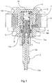
- the control device illustrated in particular in figure 1 , comprises a control ring 1, for example a winding crown, intended to be actuated by a user to act on a function of a watch movement, not shown.
- This function can relate to the winding of the mainspring and / or a correction of a display and / or a neutral position.
- the control device also comprises a control rod 2, kinematically connecting the control ring 1 to the movement.
- the control rod 2 has for example a polygonal cross-section or cross, cooperating with functional members actuated by a complementary mechanism, to activate different functions of the kind set on time, reassembly or neutral.
- a crown tube 3 is rigidly mounted on a middle part 4, by welding or any other means.
- the crown tube 3 is traversed by the control rod 2.
- the control device further comprises a mounting means for holding and rotating the control ring 1 on the crown tube 3.
- This mounting means comprises an elastic ring 5, also called “circlips”.
- the control ring 1 has a substantially cylindrical axial housing 6 in which, during assembly, the portion of the crown tube 3 projecting on the middle part 4 engages.
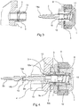
- the mounting means also comprises a radial slot 7, illustrated for example in FIG. figure 2 , formed in the control ring 1 and opening on the housing 6 on at least a portion of its radial extension.
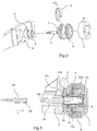
- the mounting means also comprises a complementary radial slot 8, illustrated in particular in FIG. figure 3 , substantially of the same width as the radial slot 7 and provided on the crown tube 3.
- the radial slot 7 and the complementary radial slot 8 are located in the same transverse plane so as to allow assembly and engagement of the ring This latter, once mounted, is engaged at least partially in the radial slot 7 and in the complementary slot 8, thus blocking the axial withdrawal of the control ring 1 from the crown tube 3.
- control ring 1 is fixed, since it is connected to the crown tube 3 by the ring 5. It can therefore serve as a reference for the positioning of the control rod 2.
- the control ring 1 advantageously comprises on its periphery a handling member 9 also constituting a seal covering in particular the elastic ring 5.
- the control device also comprises adjustment means for automatically adjusting the length of the subassembly constituted by the control ring 1 and the control rod 2.
- the adjustment means comprise in particular the housing 6 formed in the control ring 1, in which is engaged an axial portion of the crown tube 3.
- the adjustment means also comprise an end portion of the control rod 2.
- the end portion comprises a piston 10 fixed rigidly, for example by screwing, on the end of a first rod portion 2a of the control rod 2.
- the piston 10 has for this purpose a tapping 10a at one of its ends.
- the adjustment means also comprise a spring 11 disposed in the housing 6 between the end of the piston 10 and a support located in said housing 6, so as to axially constrain the first rod portion 2a towards the movement.
- the piston 10 is slidably mounted in a pinch sleeve 12 integral in rotation with the control ring 1.
- the spring 11 is then disposed in the pinch sleeve 12.
- the pinch sleeve 12 is driven into the ring 1.
- the assembly thus formed is then engaged in said housing 6.
- the crown tube 3 internally has an additional circular groove 8a and radial, in which is disposed a seal 13, in particular for sealing between said crown tube 3 and the outer periphery of the sleeve 12.
- the figure 4 is a sectional view of the control device of the figure 1 in a functional state, for example to raise a winding spring.
- the first rod portion 2a is connected to a second rod portion 2b, by means of a coupling / uncoupling means 14.
- the second rod portion 2b is kinematically connected to the watch movement, while the first rod portion 2a has at one of its ends the piston 10.
- the coupling / uncoupling means 14 comprises on the first rod portion 2a, a polygonal and conical end 14a and on the second rod portion 2b an end forming a complementary polygonal cross-sectional coupling housing 14b receiving said conical end and polygonal 14a.
- the spring 11 axially constrains the control rod 2 through the engagement of the polygonal end and conical 14a in the coupling housing 14b.
- This elastically constrained coupling having complementary shapes makes it possible to obtain sufficient clamping to compensate for the mechanical backlash in translation of the control rod 2 and in rotation at the level of the coupling / uncoupling means 14 and for any functional position of the second part of the rod 2b relative to the movement.
- the figure 5 is a sectional view of the control device of the figure 1 in a non-functional state in which the control rod 2 is returned to a retracted position.
- the first rod portion 2a integral with the piston 10
- the first rod portion 2a is on the one hand displaced in a direction corresponding to a compression of the spring 11 and secondly uncoupled from the second rod portion 2b.
- the latter remains for example in functional connection with the movement.
- the piston 10 has on a portion of its length, in the extension of the first rod portion 2a, a polygonal portion 10a, for example of square or triangular cross section.
- the pinch sleeve 12 has a drive portion 12a in which the polygonal portion 10a slides.
- the driving portion 12a has a shape complementary to the polygonal portion 10a, thus allowing its sliding and ensuring its rotational drive via the control ring 1.
- the pinch sleeve 12 also has, in the extension of the driving portion 12a, a circular portion 12b in which the piston 10 slides.
- the circular portion 12b presents dimensions permitting rotation of the piston 10.
- the figure 5 shows the control device of the figure 1 in a non-functional state, in which the control rod 2, in this case the first rod portion 2a and the piston 10, are arranged in a retracted position.
- the piston 10 has in the extension of the polygonal portion 10a, a cylindrical portion 10b.
- the cylindrical portion 10b is used to retain the piston 10 in the sleeve 12, when the polygonal portion 10a, engaged in the drive portion 12a, reaches the end of the race.
- the cylindrical portion 10b can not engage the drive portion 12a, but may abut against said drive portion 12a due to the extension of the spring 11.
- the piston 10 and therefore the rod 2 thus have a sliding stroke limited by the opening section of the driving portion 12a, in the direction of the watch movement.
- the stroke of the piston 10 in the opposite direction is limited by the bulk of the spring 11 in maximum compression.
- the pinch sleeve 12 advantageously has at its end opposite to that constituting the drive portion 12a, a cylindrical shape 12c, driven into the control ring 1 to ensure the transmission of the rotational movement.
- the cylindrical shape 12c can also be driven out and stuck in the control ring 1.
- control rod 2 is made in one piece.
- the broached sleeve 12 has a shape identical to that of the driving portion 12a over a length sufficient to allow the polygonal portion 10a to remain integral in rotation with said broach sleeve 12 and throughout its entire travel. translation. The operator will then maintain the first rod portion 2a in the retracted position, by any means, including manual, to clear the movement.
Landscapes
- Physics & Mathematics (AREA)
- General Physics & Mathematics (AREA)
- Electric Clocks (AREA)
- Springs (AREA)
Claims (11)
- Betätigungsvorrichtung für ein Uhrwerk, welche folgendes umfasst:- eine Kronenhülse (3), die auf ein Gehäusemittelteil (4) montiert ist,- eine Betätigungskrone (1), die über ein Montagemittel (5, 7, 8) drehbar auf der Kronenhülse (3) montiert ist,- eine Betätigungsstange (2), die drehbar durch die Kronenhülse (3) hindurch montiert ist, wobei die Stange die Betätigungskrone (1) kinematisch mit dem Uhrwerk verbindet, und- Einstellmittel zum automatischen Einstellen der Länge der Unterbaugruppe bestehend aus der Betätigungskrone (1) und der Betätigungsstange (2), wobei die Einstellmittel folgendes umfassen:- eine (6) in der Betätigungskrone (1) vorgesehene Aufnahme, in die ein axialer Abschnitt der Kronenhülse (3) eingreift,- einen Endabschnitt der Betätigungsstange (2), wie zum Beispiel ein zylindrischer Teil (10b), der in der Kronenhülse (3) translatorisch bewegt werden kann,- und eine Feder (11), die in der Aufnahme (6) zwischen dem Endabschnitt und einer in der Aufnahme (6) befindlichen Auflage angeordnet ist, so dass die Betätigungsstange (2) in Richtung des Uhrwerks axial beansprucht wird, dadurch gekennzeichnet, dass das Montagemittel (5, 7, 8) so gestaltet ist, dass die Regulierungskrone (1) in Bezug auf die Kronenhülse (3) in einer einzigen axialen Position fest gehalten werden kann.
- Betätigungsvorrichtung nach Anspruch 1, dadurch gekennzeichnet, dass die Betätigungsstange (2) einen ersten Stangenteil (2a) umfasst, der translatorisch beweglich ist, drehbar ist und mit einem Kolben (10) verbunden ist, sowie einen zweiten Stangenteil (2b), der dazu bestimmt ist, fest und drehbar mit dem Uhrwerk verbunden zu sein, wobei der erste (2a) und der zweite Stangenteil (2b) über ein Kopplungs-/Entkopplungsmittel (14) miteinander verbunden sind.
- Betätigungsvorrichtung nach Anspruch 2, dadurch gekennzeichnet, dass das Kopplungs-/Entkopplungsmittel (14) am ersten Stangenteil (2a) ein vieleckiges, konisches Ende (14a) und am zweiten Stangenteil (2b) eine Kopplungsaufnahme (14) mit vieleckigem Querschnitt umfasst, die das konische, vieleckige Ende (14a) aufnimmt.
- Betätigungsvorrichtung nach einem der Ansprüche 2 oder 3, dadurch gekennzeichnet, dass der Endabschnitt den Kolben (10) umfasst, der starr auf einem Ende des ersten Stangenteils (2a) befestigt ist.
- Betätigungsvorrichtung nach Anspruch 4, dadurch gekennzeichnet, dass der Kolben (10) gleitend in eine Spindelhülse (12) montiert ist, die in die Betätigungskrone (1) getrieben wird und mit der Betätigungskrone (1) drehbar verbunden ist, wobei sich die Spindelhülse (12) in der Aufnahme (6) erstreckt und die Feder (11), an welcher der Kolben (10) anliegt, enthält.
- Betätigungsvorrichtung nach Anspruch 5, dadurch gekennzeichnet, dass der Kolben (10) auf zumindest einem Abschnitt seiner Länge einen vieleckigen Teil (10a) aufweist, wobei die Spindelhülse (12) auf zumindest einem Längenabschnitt ein Antriebsteil (12a) in einer die vieleckige Form ergänzenden Form aufweist, so dass das axiale Gleiten des Kolbens (10) möglich ist und dessen Drehantrieb durch die Betätigungskrone (1) gewährleistet wird.
- Betätigungsvorrichtung nach einem der Ansprüche 1 bis 6, dadurch gekennzeichnet, dass das Montagemittel einen elastischen Ring (4) umfasst, einen radialen (7) und umlaufenden Spalt, der in der Betätigungskrone (1) vorgesehen ist und zur Aufnahme (6) auf zumindest einem Teil seiner Verlängerung führt, und einen auf der Kronenhülse (3) vorgesehenen radialen ergänzenden Spalt (8) mit der im Wesentlichen gleichen Breite, wobei sich der radiale Spalt (7) und der ergänzende radiale Spalt (8) auf ein und derselben Querebene befinden, so dass die Montage des elastischen Rings (5) möglich ist.
- Betätigungsvorrichtung nach Anspruch 7, dadurch gekennzeichnet, dass die Betätigungskrone (1) an ihrem Rand ein Betätigungselement (9) umfasst, welches eine den elastischen Ring (5) bedeckende Dichtung bildet.
- Betätigungsvorrichtung nach Anspruch 5 oder 6, dadurch gekennzeichnet, dass die Kronenhülse (3) innen eine zusätzliche runde Rille (8a) aufweist, in der eine Dichtung (13) angeordnet ist, welche die Kronenhülse (3) und den Außenrand der Spindelhülse (12) gegeneinander abdichtet.
- Betätigungsvorrichtung nach einem der Ansprüche 1 bis 9, dadurch gekennzeichnet, dass die Betätigungskrone (1) und die Betätigungsstange (2) jeweils eine Aufzugskrone und eine Aufzugswelle bilden.
- Zeitmessgerät, welches eine Betätigungsvorrichtung gemäß einem der Ansprüche 1 bis 10 umfasst.
Applications Claiming Priority (1)
| Application Number | Priority Date | Filing Date | Title |
|---|---|---|---|
| CH01617/11A CH705590B1 (fr) | 2011-10-03 | 2011-10-03 | Dispositif de commande pour mouvement horloger. |
Publications (3)
| Publication Number | Publication Date |
|---|---|
| EP2579103A2 EP2579103A2 (de) | 2013-04-10 |
| EP2579103A3 EP2579103A3 (de) | 2017-11-08 |
| EP2579103B1 true EP2579103B1 (de) | 2019-09-04 |
Family
ID=46980783
Family Applications (1)
| Application Number | Title | Priority Date | Filing Date |
|---|---|---|---|
| EP12185183.6A Active EP2579103B1 (de) | 2011-10-03 | 2012-09-20 | Steuervorrichtung für Uhrwerk |
Country Status (2)
| Country | Link |
|---|---|
| EP (1) | EP2579103B1 (de) |
| CH (1) | CH705590B1 (de) |
Families Citing this family (2)
| Publication number | Priority date | Publication date | Assignee | Title |
|---|---|---|---|---|
| EP2796939B1 (de) * | 2013-04-23 | 2022-03-30 | ETA SA Manufacture Horlogère Suisse | Stab mit gebrochenen Elementen, und entsprechendes Zusammenbauverfahren |
| CN115685716A (zh) * | 2021-07-28 | 2023-02-03 | 华为技术有限公司 | 智能手表 |
Family Cites Families (6)
| Publication number | Priority date | Publication date | Assignee | Title |
|---|---|---|---|---|
| US322680A (en) * | 1885-07-21 | Watch-case | ||
| CH344369A (fr) | 1958-12-03 | 1960-01-31 | Jeanneret Frederic | Tige de remontoir de longueur ajustable |
| CH448902A (fr) | 1965-05-21 | 1968-04-11 | Gunzinger Freres S A | Dispositif de remontage et de mise à l'heure à tige brisée d'une montre étanche |
| CH1445170A4 (de) * | 1970-09-30 | 1975-03-14 | ||
| FR2934904A1 (fr) * | 2008-08-05 | 2010-02-12 | Francois Caronia | Unite de reglage pour cadran d'horloge, montre munie de l'unite de reglage et son procede de reglage. |
| CH700383B1 (de) * | 2009-02-13 | 2013-03-15 | Raphael Fleischhauer | Uhrengehäuse. |
-
2011
- 2011-10-03 CH CH01617/11A patent/CH705590B1/fr unknown
-
2012
- 2012-09-20 EP EP12185183.6A patent/EP2579103B1/de active Active
Non-Patent Citations (1)
| Title |
|---|
| None * |
Also Published As
| Publication number | Publication date |
|---|---|
| EP2579103A2 (de) | 2013-04-10 |
| EP2579103A3 (de) | 2017-11-08 |
| CH705590A2 (fr) | 2013-04-15 |
| CH705590B1 (fr) | 2016-04-15 |
Similar Documents
| Publication | Publication Date | Title |
|---|---|---|
| EP1676177B1 (de) | Armbanduhr-drückstück-aufzieh-knopf-steuereinrichtung | |
| EP2746870B1 (de) | Abnehmbares Kronrad | |
| CH712804B1 (fr) | Pièce d'horlogerie avec poussoir escamotable. | |
| EP2915445B1 (de) | Vorrichtung und Verfahren zum drehbaren Zusammenbau von mindestens zwei Teilen, und Einheit aus den zwei zusammengebauten Teilen | |
| CH703455A1 (fr) | Couronne et procede d'activation d'une telle couronne sur une boîte de montre. | |
| EP2182417A2 (de) | Kronrad zum Aufschrauben und Orientierungsverfahren eines solchen Kronrads auf einem Armbanduhrengehäuse | |
| EP2579103B1 (de) | Steuervorrichtung für Uhrwerk | |
| CH710110B1 (fr) | Pièce d'horlogerie. | |
| EP1684133A2 (de) | Uhrwerk | |
| CH714005A2 (fr) | Tête couronne comprenant une soupape de sécurité pour pièce d'horlogerie. | |
| EP1853977B1 (de) | Blockierbarer drücker | |
| EP3742235B1 (de) | Druckknopfsystem und dieses umfassende uhr | |
| CH706232A2 (fr) | Dispositif de commande et de réglage comportant une couronne et un poussoir coaxial. | |
| EP4092490B1 (de) | Steuervorrichtung für ein uhrwerk mit taktiler rückmeldung und uhrwerk, insbesondere armbanduhr, mit einer solchen vorrichtung | |
| FR2995412A1 (fr) | Ensemble de couronne de montre a verrouillage central | |
| CH708958B1 (fr) | Poussoir de pièce d'horlogerie. | |
| CH706703B1 (fr) | Ensemble de couronne de remontoir de montre à effet télescopique. | |
| CH706893A2 (fr) | Ensemble de couronne télescopique à effet d'effacement dans le boîtier d'une montre. | |
| CH708126A2 (fr) | Joint, poussoir et couronne de pièce d'horlogerie. | |
| EP2653937B1 (de) | Abdichtvorrichtung für Minuten-Repetierwerk | |
| CH716210A2 (fr) | Système de bouton-poussoir, et pièce d'horlogerie le comprenant. | |
| EP3492995A1 (de) | Kranzsystem für uhr | |
| CH718165A2 (fr) | Ensemble de commande pour mouvement d'horlogerie d'une pièce d'horlogerie. | |
| FR3113744A1 (fr) | Dispositif de commande à couronne interchangeable pour pièce d’horlogerie | |
| CH720974A2 (fr) | Couronne de montre rétractable |
Legal Events
| Date | Code | Title | Description |
|---|---|---|---|
| PUAI | Public reference made under article 153(3) epc to a published international application that has entered the european phase |
Free format text: ORIGINAL CODE: 0009012 |
|
| AK | Designated contracting states |
Kind code of ref document: A2 Designated state(s): AL AT BE BG CH CY CZ DE DK EE ES FI FR GB GR HR HU IE IS IT LI LT LU LV MC MK MT NL NO PL PT RO RS SE SI SK SM TR |
|
| AX | Request for extension of the european patent |
Extension state: BA ME |
|
| REG | Reference to a national code |
Ref country code: HK Ref legal event code: DE Ref document number: 1181858 Country of ref document: HK |
|
| PUAL | Search report despatched |
Free format text: ORIGINAL CODE: 0009013 |
|
| AK | Designated contracting states |
Kind code of ref document: A3 Designated state(s): AL AT BE BG CH CY CZ DE DK EE ES FI FR GB GR HR HU IE IS IT LI LT LU LV MC MK MT NL NO PL PT RO RS SE SI SK SM TR |
|
| AX | Request for extension of the european patent |
Extension state: BA ME |
|
| RIC1 | Information provided on ipc code assigned before grant |
Ipc: G04B 3/04 20060101AFI20170929BHEP Ipc: G04B 37/10 20060101ALI20170929BHEP |
|
| STAA | Information on the status of an ep patent application or granted ep patent |
Free format text: STATUS: REQUEST FOR EXAMINATION WAS MADE |
|
| 17P | Request for examination filed |
Effective date: 20180426 |
|
| RBV | Designated contracting states (corrected) |
Designated state(s): AL AT BE BG CH CY CZ DE DK EE ES FI FR GB GR HR HU IE IS IT LI LT LU LV MC MK MT NL NO PL PT RO RS SE SI SK SM TR |
|
| GRAP | Despatch of communication of intention to grant a patent |
Free format text: ORIGINAL CODE: EPIDOSNIGR1 |
|
| STAA | Information on the status of an ep patent application or granted ep patent |
Free format text: STATUS: GRANT OF PATENT IS INTENDED |
|
| INTG | Intention to grant announced |
Effective date: 20190415 |
|
| GRAS | Grant fee paid |
Free format text: ORIGINAL CODE: EPIDOSNIGR3 |
|
| GRAA | (expected) grant |
Free format text: ORIGINAL CODE: 0009210 |
|
| STAA | Information on the status of an ep patent application or granted ep patent |
Free format text: STATUS: THE PATENT HAS BEEN GRANTED |
|
| AK | Designated contracting states |
Kind code of ref document: B1 Designated state(s): AL AT BE BG CH CY CZ DE DK EE ES FI FR GB GR HR HU IE IS IT LI LT LU LV MC MK MT NL NO PL PT RO RS SE SI SK SM TR |
|
| REG | Reference to a national code |
Ref country code: GB Ref legal event code: FG4D Free format text: NOT ENGLISH |
|
| REG | Reference to a national code |
Ref country code: CH Ref legal event code: EP |
|
| REG | Reference to a national code |
Ref country code: AT Ref legal event code: REF Ref document number: 1176221 Country of ref document: AT Kind code of ref document: T Effective date: 20190915 |
|
| REG | Reference to a national code |
Ref country code: DE Ref legal event code: R096 Ref document number: 602012063567 Country of ref document: DE |
|
| REG | Reference to a national code |
Ref country code: IE Ref legal event code: FG4D Free format text: LANGUAGE OF EP DOCUMENT: FRENCH |
|
| REG | Reference to a national code |
Ref country code: CH Ref legal event code: NV Representative=s name: BOVARD SA NEUCHATEL CONSEILS EN PROPRIETE INTE, CH |
|
| REG | Reference to a national code |
Ref country code: NL Ref legal event code: MP Effective date: 20190904 |
|
| REG | Reference to a national code |
Ref country code: LT Ref legal event code: MG4D |
|
| PG25 | Lapsed in a contracting state [announced via postgrant information from national office to epo] |
Ref country code: NO Free format text: LAPSE BECAUSE OF FAILURE TO SUBMIT A TRANSLATION OF THE DESCRIPTION OR TO PAY THE FEE WITHIN THE PRESCRIBED TIME-LIMIT Effective date: 20191204 Ref country code: BG Free format text: LAPSE BECAUSE OF FAILURE TO SUBMIT A TRANSLATION OF THE DESCRIPTION OR TO PAY THE FEE WITHIN THE PRESCRIBED TIME-LIMIT Effective date: 20191204 Ref country code: FI Free format text: LAPSE BECAUSE OF FAILURE TO SUBMIT A TRANSLATION OF THE DESCRIPTION OR TO PAY THE FEE WITHIN THE PRESCRIBED TIME-LIMIT Effective date: 20190904 Ref country code: LT Free format text: LAPSE BECAUSE OF FAILURE TO SUBMIT A TRANSLATION OF THE DESCRIPTION OR TO PAY THE FEE WITHIN THE PRESCRIBED TIME-LIMIT Effective date: 20190904 Ref country code: HR Free format text: LAPSE BECAUSE OF FAILURE TO SUBMIT A TRANSLATION OF THE DESCRIPTION OR TO PAY THE FEE WITHIN THE PRESCRIBED TIME-LIMIT Effective date: 20190904 Ref country code: SE Free format text: LAPSE BECAUSE OF FAILURE TO SUBMIT A TRANSLATION OF THE DESCRIPTION OR TO PAY THE FEE WITHIN THE PRESCRIBED TIME-LIMIT Effective date: 20190904 |
|
| PG25 | Lapsed in a contracting state [announced via postgrant information from national office to epo] |
Ref country code: ES Free format text: LAPSE BECAUSE OF FAILURE TO SUBMIT A TRANSLATION OF THE DESCRIPTION OR TO PAY THE FEE WITHIN THE PRESCRIBED TIME-LIMIT Effective date: 20190904 Ref country code: LV Free format text: LAPSE BECAUSE OF FAILURE TO SUBMIT A TRANSLATION OF THE DESCRIPTION OR TO PAY THE FEE WITHIN THE PRESCRIBED TIME-LIMIT Effective date: 20190904 Ref country code: AL Free format text: LAPSE BECAUSE OF FAILURE TO SUBMIT A TRANSLATION OF THE DESCRIPTION OR TO PAY THE FEE WITHIN THE PRESCRIBED TIME-LIMIT Effective date: 20190904 Ref country code: RS Free format text: LAPSE BECAUSE OF FAILURE TO SUBMIT A TRANSLATION OF THE DESCRIPTION OR TO PAY THE FEE WITHIN THE PRESCRIBED TIME-LIMIT Effective date: 20190904 Ref country code: GR Free format text: LAPSE BECAUSE OF FAILURE TO SUBMIT A TRANSLATION OF THE DESCRIPTION OR TO PAY THE FEE WITHIN THE PRESCRIBED TIME-LIMIT Effective date: 20191205 |
|
| REG | Reference to a national code |
Ref country code: AT Ref legal event code: MK05 Ref document number: 1176221 Country of ref document: AT Kind code of ref document: T Effective date: 20190904 |
|
| PG25 | Lapsed in a contracting state [announced via postgrant information from national office to epo] |
Ref country code: PT Free format text: LAPSE BECAUSE OF FAILURE TO SUBMIT A TRANSLATION OF THE DESCRIPTION OR TO PAY THE FEE WITHIN THE PRESCRIBED TIME-LIMIT Effective date: 20200106 Ref country code: EE Free format text: LAPSE BECAUSE OF FAILURE TO SUBMIT A TRANSLATION OF THE DESCRIPTION OR TO PAY THE FEE WITHIN THE PRESCRIBED TIME-LIMIT Effective date: 20190904 Ref country code: PL Free format text: LAPSE BECAUSE OF FAILURE TO SUBMIT A TRANSLATION OF THE DESCRIPTION OR TO PAY THE FEE WITHIN THE PRESCRIBED TIME-LIMIT Effective date: 20190904 Ref country code: AT Free format text: LAPSE BECAUSE OF FAILURE TO SUBMIT A TRANSLATION OF THE DESCRIPTION OR TO PAY THE FEE WITHIN THE PRESCRIBED TIME-LIMIT Effective date: 20190904 Ref country code: RO Free format text: LAPSE BECAUSE OF FAILURE TO SUBMIT A TRANSLATION OF THE DESCRIPTION OR TO PAY THE FEE WITHIN THE PRESCRIBED TIME-LIMIT Effective date: 20190904 Ref country code: NL Free format text: LAPSE BECAUSE OF FAILURE TO SUBMIT A TRANSLATION OF THE DESCRIPTION OR TO PAY THE FEE WITHIN THE PRESCRIBED TIME-LIMIT Effective date: 20190904 |
|
| PG25 | Lapsed in a contracting state [announced via postgrant information from national office to epo] |
Ref country code: CZ Free format text: LAPSE BECAUSE OF FAILURE TO SUBMIT A TRANSLATION OF THE DESCRIPTION OR TO PAY THE FEE WITHIN THE PRESCRIBED TIME-LIMIT Effective date: 20190904 Ref country code: SK Free format text: LAPSE BECAUSE OF FAILURE TO SUBMIT A TRANSLATION OF THE DESCRIPTION OR TO PAY THE FEE WITHIN THE PRESCRIBED TIME-LIMIT Effective date: 20190904 Ref country code: SM Free format text: LAPSE BECAUSE OF FAILURE TO SUBMIT A TRANSLATION OF THE DESCRIPTION OR TO PAY THE FEE WITHIN THE PRESCRIBED TIME-LIMIT Effective date: 20190904 Ref country code: IS Free format text: LAPSE BECAUSE OF FAILURE TO SUBMIT A TRANSLATION OF THE DESCRIPTION OR TO PAY THE FEE WITHIN THE PRESCRIBED TIME-LIMIT Effective date: 20200224 |
|
| REG | Reference to a national code |
Ref country code: DE Ref legal event code: R097 Ref document number: 602012063567 Country of ref document: DE |
|
| PLBE | No opposition filed within time limit |
Free format text: ORIGINAL CODE: 0009261 |
|
| STAA | Information on the status of an ep patent application or granted ep patent |
Free format text: STATUS: NO OPPOSITION FILED WITHIN TIME LIMIT |
|
| PG2D | Information on lapse in contracting state deleted |
Ref country code: IS |
|
| PG25 | Lapsed in a contracting state [announced via postgrant information from national office to epo] |
Ref country code: IE Free format text: LAPSE BECAUSE OF NON-PAYMENT OF DUE FEES Effective date: 20190920 Ref country code: LU Free format text: LAPSE BECAUSE OF NON-PAYMENT OF DUE FEES Effective date: 20190920 Ref country code: DK Free format text: LAPSE BECAUSE OF FAILURE TO SUBMIT A TRANSLATION OF THE DESCRIPTION OR TO PAY THE FEE WITHIN THE PRESCRIBED TIME-LIMIT Effective date: 20190904 Ref country code: IS Free format text: LAPSE BECAUSE OF FAILURE TO SUBMIT A TRANSLATION OF THE DESCRIPTION OR TO PAY THE FEE WITHIN THE PRESCRIBED TIME-LIMIT Effective date: 20200105 |
|
| REG | Reference to a national code |
Ref country code: BE Ref legal event code: MM Effective date: 20190930 |
|
| 26N | No opposition filed |
Effective date: 20200605 |
|
| PG25 | Lapsed in a contracting state [announced via postgrant information from national office to epo] |
Ref country code: BE Free format text: LAPSE BECAUSE OF NON-PAYMENT OF DUE FEES Effective date: 20190930 Ref country code: SI Free format text: LAPSE BECAUSE OF FAILURE TO SUBMIT A TRANSLATION OF THE DESCRIPTION OR TO PAY THE FEE WITHIN THE PRESCRIBED TIME-LIMIT Effective date: 20190904 Ref country code: MC Free format text: LAPSE BECAUSE OF FAILURE TO SUBMIT A TRANSLATION OF THE DESCRIPTION OR TO PAY THE FEE WITHIN THE PRESCRIBED TIME-LIMIT Effective date: 20190904 |
|
| PG25 | Lapsed in a contracting state [announced via postgrant information from national office to epo] |
Ref country code: CY Free format text: LAPSE BECAUSE OF FAILURE TO SUBMIT A TRANSLATION OF THE DESCRIPTION OR TO PAY THE FEE WITHIN THE PRESCRIBED TIME-LIMIT Effective date: 20190904 |
|
| PG25 | Lapsed in a contracting state [announced via postgrant information from national office to epo] |
Ref country code: MT Free format text: LAPSE BECAUSE OF FAILURE TO SUBMIT A TRANSLATION OF THE DESCRIPTION OR TO PAY THE FEE WITHIN THE PRESCRIBED TIME-LIMIT Effective date: 20190904 Ref country code: HU Free format text: LAPSE BECAUSE OF FAILURE TO SUBMIT A TRANSLATION OF THE DESCRIPTION OR TO PAY THE FEE WITHIN THE PRESCRIBED TIME-LIMIT; INVALID AB INITIO Effective date: 20120920 |
|
| PG25 | Lapsed in a contracting state [announced via postgrant information from national office to epo] |
Ref country code: TR Free format text: LAPSE BECAUSE OF FAILURE TO SUBMIT A TRANSLATION OF THE DESCRIPTION OR TO PAY THE FEE WITHIN THE PRESCRIBED TIME-LIMIT Effective date: 20190904 |
|
| PG25 | Lapsed in a contracting state [announced via postgrant information from national office to epo] |
Ref country code: MK Free format text: LAPSE BECAUSE OF FAILURE TO SUBMIT A TRANSLATION OF THE DESCRIPTION OR TO PAY THE FEE WITHIN THE PRESCRIBED TIME-LIMIT Effective date: 20190904 |
|
| REG | Reference to a national code |
Ref country code: CH Ref legal event code: U11 Free format text: ST27 STATUS EVENT CODE: U-0-0-U10-U11 (AS PROVIDED BY THE NATIONAL OFFICE) Effective date: 20251126 |
|
| PGFP | Annual fee paid to national office [announced via postgrant information from national office to epo] |
Ref country code: DE Payment date: 20251128 Year of fee payment: 14 |
|
| PGFP | Annual fee paid to national office [announced via postgrant information from national office to epo] |
Ref country code: GB Payment date: 20251128 Year of fee payment: 14 |
|
| PGFP | Annual fee paid to national office [announced via postgrant information from national office to epo] |
Ref country code: IT Payment date: 20251128 Year of fee payment: 14 |
|
| PGFP | Annual fee paid to national office [announced via postgrant information from national office to epo] |
Ref country code: FR Payment date: 20251128 Year of fee payment: 14 |
|
| PGFP | Annual fee paid to national office [announced via postgrant information from national office to epo] |
Ref country code: CH Payment date: 20251126 Year of fee payment: 14 |
|
| REG | Reference to a national code |
Ref country code: CH Ref legal event code: R18 Free format text: ST27 STATUS EVENT CODE: U-0-0-R10-R18 (AS PROVIDED BY THE NATIONAL OFFICE) Effective date: 20260209 |
|
| REG | Reference to a national code |
Ref country code: CH Ref legal event code: R18 Free format text: ST27 STATUS EVENT CODE: U-0-0-R10-R18 (AS PROVIDED BY THE NATIONAL OFFICE) Effective date: 20260320 |