EP2581542B2 - Vantail de porte d'entrée ainsi que son procédé de fabrication - Google Patents
Vantail de porte d'entrée ainsi que son procédé de fabrication Download PDFInfo
- Publication number
- EP2581542B2 EP2581542B2 EP12185541.5A EP12185541A EP2581542B2 EP 2581542 B2 EP2581542 B2 EP 2581542B2 EP 12185541 A EP12185541 A EP 12185541A EP 2581542 B2 EP2581542 B2 EP 2581542B2
- Authority
- EP
- European Patent Office
- Prior art keywords
- door leaf
- frame
- shell
- door
- profile
- Prior art date
- Legal status (The legal status is an assumption and is not a legal conclusion. Google has not performed a legal analysis and makes no representation as to the accuracy of the status listed.)
- Active
Links
Images


Classifications
-
- E—FIXED CONSTRUCTIONS
- E06—DOORS, WINDOWS, SHUTTERS, OR ROLLER BLINDS IN GENERAL; LADDERS
- E06B—FIXED OR MOVABLE CLOSURES FOR OPENINGS IN BUILDINGS, VEHICLES, FENCES OR LIKE ENCLOSURES IN GENERAL, e.g. DOORS, WINDOWS, BLINDS, GATES
- E06B3/00—Window sashes, door leaves, or like elements for closing wall or like openings; Layout of fixed or moving closures, e.g. windows in wall or like openings; Features of rigidly-mounted outer frames relating to the mounting of wing frames
- E06B3/70—Door leaves
- E06B3/82—Flush doors, i.e. with completely flat surface
- E06B3/822—Flush doors, i.e. with completely flat surface with an internal foursided frame
-
- E—FIXED CONSTRUCTIONS
- E06—DOORS, WINDOWS, SHUTTERS, OR ROLLER BLINDS IN GENERAL; LADDERS
- E06B—FIXED OR MOVABLE CLOSURES FOR OPENINGS IN BUILDINGS, VEHICLES, FENCES OR LIKE ENCLOSURES IN GENERAL, e.g. DOORS, WINDOWS, BLINDS, GATES
- E06B3/00—Window sashes, door leaves, or like elements for closing wall or like openings; Layout of fixed or moving closures, e.g. windows in wall or like openings; Features of rigidly-mounted outer frames relating to the mounting of wing frames
- E06B3/70—Door leaves
- E06B2003/7059—Specific frame characteristics
- E06B2003/7074—Metal frames
- E06B2003/7076—Metal frames insulated
-
- E—FIXED CONSTRUCTIONS
- E06—DOORS, WINDOWS, SHUTTERS, OR ROLLER BLINDS IN GENERAL; LADDERS
- E06B—FIXED OR MOVABLE CLOSURES FOR OPENINGS IN BUILDINGS, VEHICLES, FENCES OR LIKE ENCLOSURES IN GENERAL, e.g. DOORS, WINDOWS, BLINDS, GATES
- E06B3/00—Window sashes, door leaves, or like elements for closing wall or like openings; Layout of fixed or moving closures, e.g. windows in wall or like openings; Features of rigidly-mounted outer frames relating to the mounting of wing frames
- E06B3/70—Door leaves
- E06B2003/7059—Specific frame characteristics
- E06B2003/7082—Plastic frames
Definitions
- the invention relates to a door leaf for a house door, a house door provided with such a door leaf, and a manufacturing method for such a door leaf.
- Front doors are doors that can be used as the outer closure of a building.
- the invention relates in particular to front doors to be used as the main entrance of residential buildings, in particular single-family houses, apartment buildings, terraced houses, semi-detached houses.
- Such front doors must primarily fulfill the two functions of burglary protection and thermal insulation.
- front doors As materials for front doors, there are mainly front doors made of wood, plastic or metal on the market. Although wood and plastic have lower thermal conductivity compared to metal materials, so that thermal protection seems to be easier to achieve in principle, on the other hand wood and plastic are usually less resistant than metals, so that front doors based on metal materials are usually more robust, warp less even with frequent and longer use and provide a good basis for increased burglary protection. Front doors based on metal materials have a high quality impression and can be manufactured very precisely with small gap dimensions and can also be operated over a longer period of time. Because of this, the front doors can be designed to close more tightly and a high level of burglary protection can be achieved.
- the invention therefore applies exclusively to front doors based on metal materials.
- the EP 1 568 842 A2 explains the construction principles currently used for such metal front doors.
- Front doors have a door leaf, also referred to as a door leaf, and a door frame, also referred to as a frame.
- the door frame can have a glazed side part, for example.
- the door leaf usually has a door leaf frame and a door panel.
- door panels In the previous production of house doors available on the market, it has been standard for house door manufacturers to build the door leaf frame based on metal profiles and to provide it with locking technology - door hinges, locks, etc. - with door panels usually being supplied by door panel manufacturers.
- the door panel manufacturers had different front door motifs in their range, which were developed by designers.
- the door panels have usually been constructed as sandwich panels, with a motif panel to be arranged on the outside carrying the motif, with an inner panel to be arranged on the inside and insulation between the two panels also being present. Depending on the motif selected, such door panels designed as sandwich panels are also provided with glazing cut-outs with glazing.
- EP 1 568 842 A2 shows different production methods for known wing-covering configurations.
- the insulation and the inner panel of the door panel designed as a sandwich panel are cut out, while the motif panel is left essentially as large as the outer broad side of the door leaf, so that only the motif panel rests on the outside of the door leaf frame.
- the EP 1 568 842 A2 therefore proposes a wing-covering design, where the door panel designed as a sandwich panel rests with all its components on the outside of the door leaf frame. This allows the door panel to be processed more easily because it is cut to size as a whole.
- the door leaf frame can be designed more simply, since the insulation of the door panel can take over the thermal insulation function of the connecting webs, so that the door leaf frame only needs to be made of a simple metal profile without connecting webs.
- the invention further relates to a house door provided with such a house door leaf and to a method for producing such a house door leaf.
- the invention creates a house door leaf with a door leaf frame and the panels forming the broad sides of the door leaf and with insulation between the panels, the door leaf frame being formed from a metal half-shell and a plastic half-shell.
- a first of the panels lies on the metal half-shell, covering it to a large extent
- the second panel lies on the plastic half-shell, covering it to a large extent
- the door leaf frame is composed of frame members, the frame members each consisting of two frame member half-shells, of which a first frame member half-shell is designed as a metal profile and a second frame member half-shell is designed as a plastic profile.
- the two half-shells are formed from hollow profiles.
- the hollow sections are tubular sections.
- the hollow profiles of the plastic half-shell are designed essentially in the shape of a U-profile with two U-legs and a U-web connecting the U-legs, with stiffening webs being formed between the U-legs and/or between each U-leg and the U-web.
- the second panel is glued directly to the plastic half-shell.
- the panels lie over their entire surface on the wide-side end face of the associated half-shells, with one end edge of the panel terminating essentially flush with an outer edge delimiting the end face.
- the insulation is formed by foaming the door leaf cavity formed between the door leaf frame and the panels that rest on it.
- each of the two half-shells has at least one hook formation that engages in the door leaf cavity and is surrounded by foam through the insulation.
- the metal half-shell is thicker than the plastic half-shell in the thickness direction of the door leaf.
- At least one of the panels is preferably made of metal.
- the panels are formed from sheet metal.
- the panel to be arranged on the outside is preferably designed as a wing-covering aluminum sheet.
- the door leaf frame By constructing the door leaf frame from two half-shells, with one half-shell made of metal and the other half-shell made of plastic materials, a high-quality, rigid door leaf frame can be formed on the one hand, which provides a basis for good burglary protection, in particular due to the metal half-shell, offers a high quality impression and on the other hand, due to the plastic half-shell, there are no connecting webs made of non-metal materials. Only two sub-elements per frame rail need to be manufactured and joined together. The bond results in high rigidity and high thermal insulation capacity.
- the door panel frame extends substantially through the full thickness of the door panel so that the full thickness of the door panel can be used to provide a rigid door panel frame.
- the construction shown results in greater rigidity, which leads to improvements in the sealing effects - improved, defined gap dimensions all around the door leaf - in terms of burglary protection - improved rigidity and higher resistance class.
- frame members that consist of two frame member half-shells.
- the door leaf frame itself is then preferably manufactured in such a way that four frame bars are cut off to the appropriate length and then connected to one another.
- the connection at the corners is preferably carried out via corner connectors engaging in the metal half-shells. Due to the fastening of the corner connectors to the metal elements of the door leaf frame, a strong and rigid connection can be achieved.
- the second half-shells of the frame rail can also be additionally reinforced with corner brackets. Plastic corner brackets are preferably used for this purpose.
- the joining of the two frame member half-shells is preferably done - as is the case in principle is already known for connecting metal profiles with plastic connecting bars - via tongue and groove connections.
- at least two tongue and groove connections are provided here between the half-shells, which are spaced apart from one another and extend along the length of the frame bars.
- the tongue and groove connections are preferably provided near the end-side boundary walls of the half-shells.
- a particularly high level of reinforcement results when both half-shells are each formed from hollow profiles, in particular tubular profiles.
- a half-shell base body is preferably provided, which is essentially U-shaped and can be designed with a thicker wall, with stiffening webs that can have a thinner wall thickness running between the U-legs one below the other or between the U-legs and a web connecting the U-legs. At least one of the stiffening webs can also have a stiffening tube profile.
- these chambers can be formed within the plastic hollow profile, which is particularly useful for stiffening and thermal insulation.
- these chambers can be foamed with an intumescent insulation material.
- not only an outer panel forming the outside of the house door leaf rests on the outside of the door leaf frame.
- a panel provided on the inside is designed as a cover panel, so that it covers at least a large part of the door leaf frame on the inside of the house door leaf.
- this means that the front door leaf also has a visually appealing design on the inside; there is no step on the inside due to the door leaf frame.
- the panel is made of sheet metal, e.g.
- Light metal sheet is formed - achieve additional stiffening due to the support of the inner panel. Due to the outside and inside support of the two panels, a large cavity is created inside the door leaf, which can be used for insulation purposes.
- the remaining cavities in the door leaf frame are preferably filled with foam.
- Cavities that remain between the door leaf frame and other inserts within the door leaf frame are preferably filled with foam.
- the half-shells are also particularly preferably filled with foam.
- the metal half-shell preferably carries functional elements of the door, such as in particular door hinges or a multi-point lock. It is further preferred that the metal half-shell is made thicker than the plastic half-shell. As a result, a larger area of the door leaf thickness is used for the more rigid metal material and more space can be created for the functional elements and their attachment. More preferably, the plastic half-shell is assigned to an outside of the door leaf, with a panel forming the outside of the door leaf resting on the plastic half-shell. The plastic half-shell is thus located between the outside and the metal half-shell with the functional elements. This improves the insulation effect, functionality and burglary protection.
- the panels preferably rest over their entire surface on the broad-side surfaces of the half-shells. The use of the entire surface of the half-shells as a support surface for the panels results in an attractive design, good fastening options and high rigidity.
- the attachment between the panels and the door leaf frame is preferably effected in a material-to-material manner, preferably by gluing.
- the broad-side contact surfaces of the half-shells, on which the panels rest, are preferably provided with at least one groove-shaped depression extending in the longitudinal direction of the frame members. More generally, the bearing surfaces are not completely flat, but are designed with indentations. By forming such indentations, the bondability and the hold of the panels on the half-shells can be improved.
- At least one of the two half-shells preferably both half-shells, is provided with a hook formation that engages in the door leaf cavity on the areas facing the door leaf cavity, then a particularly strong bond can be achieved between the foam filling and the door leaf frame when the hook formation is foamed.
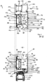
- In 1 is an interior view of a front door 10 shown with a door frame 12 and a door panel 14.
- the door panel 14 is pivoted inwards on the door frame 12 by means of door hinges 16 .
- on the inside 1 shown inside is a door handle 18 and a rosette 20 is provided for the inner end of a lock cylinder of a door lock.
- FIG. 2 shows the outside view of the front door 10 from 1 .
- the door frame 12 covers the outer edges of the door leaf 14 on the outside.
- a front door handle 22 and only a rosette 24, but no door handle 18, are also provided on the outside.
- inner broad side 26 which remains visible within the door frame 12 when the front door 10 is closed, is formed entirely by an inner panel 28.
- the outer wide side 30 of the door leaf 14 shown is, insofar as it is visible within the door frame 12, formed entirely by an outer panel 32.
- the outer panel 32 is designed as a motif plate 34 and has different decorative elements 36 and designs depending on the motif selected. A large number of different motifs with different ones are conceivable here.
- the door leaf 14 has a door leaf frame 40 and the panels 28, 32 forming the door leaf broad sides 26, 30 and insulation 38 between the panels 28, 32.
- the door leaf frame 40 is formed from a metal half-shell 42 and a plastic half-shell 44 .
- the door leaf frame 40 is made up of an upper horizontal frame member 46, a lower horizontal frame member 48, a lock-side vertical frame member 50 and a hinge-side vertical frame member 52.
- Each of the frame rails 46 , 48 , 50 , 52 consists of two frame rail half-shells, with a first frame rail half-shell 54 being formed from a metal profile 56 and a second frame rail half-shell 58 being formed from a plastic profile 60 .
- the metal profile 56 is, for example, a hollow profile in the form of a tubular profile 62 made of metal, in particular light metal, such as aluminum alloys or the like.
- the plastic profile 60 is made of a suitable plastic, such as polyamide, aramid or fiber-reinforced plastic materials (CFRP, GFRP) or the like.
- the plastic profile 60 is preferably a hollow profile in the form of a tubular profile 64.
- the plastic profile 60 of the plastic half-shell 44 is preferably essentially in the form of a U-profile with two U-legs 66, 68 and a U-web 70 connecting the U-legs 66, 68.
- a transverse stiffening web 72 is provided between the legs 66, 68 of the U.
- a diagonally running diagonal stiffening web 74 is provided in the corner regions.
- the transverse stiffening web 72 has a rectangular profile 76 with stiffening ribs 78 .
- the frame beam half-shells 54, 58 have hook formations 84 protruding into the door leaf cavity 82, which is formed between the panels 28, 32 and the door leaf frame 40, on the inner side 80 facing the interior space enclosed by the door leaf frame 40.
- the plastic profile 60 has an inwardly protruding projection 86 on the inner side 80 facing the door leaf cavity 82 in the region of the transition between the inner U-leg 68 and the U-web 70 .
- the inner wall 88 of the frame member which is formed partially on the inner U-leg 68 for example, has on the plastic profile 60 a wall area 90 extending in the thickness direction and a wall area 92 extending obliquely into the interior and outwards.
- the U-web 70 is guided correspondingly obliquely in the area of the projection 86 beyond the wall area 90 extending in the direction of thickness and merges in one piece into the oblique wall area 92 in the area of the projection 86 .
- the surface 94 of the plastic profile 60 directed outwards is enlarged towards the middle of the broad sides 26, 30.
- This outward surface 94 serves as a bearing surface 96 for the outer panel 32.
- the bearing surface 96 is provided with a plurality of indentations 98.
- the depressions 98 are provided in the form of channels or beads along the longitudinal extension of the plastic profile 60 .
- three or more parallel indentation grooves are spaced side-by-side.
- the hook formation 84 acts integrally on the projection 86 .
- the hook formation 84 has a sloping area 100 extending obliquely inwards from the tip of the projection 86, which forms the edge between the inner wall 88 and the bearing surface 96, which is adjoined by an area 102 protruding inwards in the thickness direction.
- an end flange area 104 which protrudes back towards the U-shaped main body of the plastic hollow profile.
- At least two tongue-and-groove connections 106 are provided between the two frame rail half-shells 54 and engage in one another in a form-fitting manner.
- the tongue and groove connections 106 are designed with dovetail-type rear grips.
- the plastic profile 60 has thickenings 108 at the ends of wall regions extending in the thickness direction of the door leaf 14, which engage in C-profile-shaped groove edges 110 on the metal profile 56 in a form-fitting manner and secured against being pulled out.
- the thickenings 108 are provided on the free end edges of the two legs 66, 68 of the U.
- the end areas of the U-legs 66, 68 are designed to be offset and set back into the profile interior, as shown in the drawings.
- the metal profile 56 is a tubular profile 62 which is essentially rectangular with two profile walls 112, 114 extending parallel to the broad sides and two profile walls 116, 118 extending essentially in the thickness direction.
- the outer profile wall 116 which is arranged on the very inside of the door leaf 14 and extends in the thickness direction, is wider than the inner profile wall 114, which extends inside the door leaf frame 40 at the transition to the plastic profile 60 and extends parallel to the broad side direction 0 of the door leaf frame 40 and forms a stop fold 122 of the door leaf 14.
- this outer profile wall 112 which extends parallel to the broad lateral direction, projects beyond the inner wall 88 of the door leaf frame 40, so that a projection 128 is formed on the edge region between the inner wall 88 and an outwardly directed surface 126 forming a bearing surface 124, comparable to the projection 86 of the plastic profile 60 is.
- the hook formation 84 is integrally attached to this projection 128 in the same way as in the case of the plastic profile 60 embodied with a sloping area 100 , area 102 protruding inwards in the thickness direction and end flange area 104 .
- the inner profile wall 118 extending in the direction of thickness forms, together with the inner leg 68 of the U, the inner wall 88 of the door leaf frame 40.
- This inner profile wall 118 which extends in the direction of thickness, has, similar to the inner leg 68 of the U, a wall area 130 extending in the direction of thickness and an inclined wall area 132 for forming the approximately triangular projection 128.
- the inner profile wall 114 which extends parallel to the broad side direction, is essentially flat and plate-shaped in the exemplary embodiment shown here, with the C-shaped groove edges 110 being formed by two mutually facing hook-shaped projections 134 on the two edge regions near the end face 120 of the door leaf frame 40 on the one hand and near the inner wall 88 of the door leaf frame 40 on the other.
- the outer profile wall 116 extending in the direction of thickness has a C-shaped, essentially rectangular indentation-e.g. designed as a C-shaped profile recess 136-for forming a receiving groove for a seal or the like.
- the lower horizontal frame member 48 has the same profile as the other frame members 46, 50, 52. Accordingly, the lower horizontal frame bar 48 is also provided with the stop fold 122 . In this lower horizontal frame member 48, a seal 138 for sealing the lower door gap 140 is provided in the depression of the C-shaped profile recess 136, which is formed in the outer profile wall 116 extending in the thickness direction.
- the entire outwardly directed surface 126 of the outer profile wall 112 extending parallel to the broad side direction is designed as a bearing surface 124 for the inner panel 28 .
- the inner panel 28 covers the entire surface of the wing on this outwardly directed surface 126 of the outer profile wall 112 extending parallel to the direction of the broad side.
- only a few indentations 142 are provided in the bearing surface, which indentations 142 serve to improve a material connection between the panel 28 and the metal profile 56 .
- the depressions 142 are formed, for example, as channels or grooves extending along the metal profile.
- the metal half-shell 42 has a greater extent in the thickness direction of the door leaf 14 than the plastic half-shell 44.
- the first frame rail half-shell 54 extends over 55% to 80% of the thickness of the door leaf frame 40, and the rest of 65% to 20%, respectively, is occupied by the second frame rail half-shell 58.
- the structure of the door leaf 14 in the thickness direction in the area of the door leaf frame 40 of an exemplary embodiment is described in more detail below.
- an outer panel 150 which is made of aluminum or other light metal (in particular aluminum alloy), for example, followed by an outer profile 152 made of a plastic material, for example the plastic profile 60, e.g. designed as a polyamide profile (thermally insulated).
- an inner panel 154 for example made of light metal, for example aluminum alloy.
- Outer panel 150 and inner panel 154 are examples of the design of the panels 28, 32.
- the panels 28, 32 rest directly on the door leaf frame 40, so that there is at most an adhesive between the panels 28, 32 and the door leaf frame 40.
- Such a construction of the door leaf 14 is comparable in terms of quality to the door leaf construction as shown in FIG EP 1 568 842 A2 is placed under protection, but not only on the outside but also on the inside, an attractive design is achieved by a wing-covering design and, in addition, the production method in large industrial series is less complex than that in EP 1 568 842 A2 solution shown with sandwich panel on the outside.
- An advantage of this new design is that the outer profile no longer has to contain a metal-non-metal composite profile, to which an aluminum sheet must also be attached. Rather, the construction is simplified and the thermal insulation is significantly improved.
- the door frame has 12 door frame spars 160 which are each constructed from a three-part frame composite profile 162 .
- the three-part frame composite profile 162 has a metal outer shell 164, for example made of aluminum, other light metal or alloys, a metal inner shell 166, for example made of aluminum, other light metal or alloys, and as a third partial element plastic insulating bars 168 - e.g. polyamide insulating bars - for thermal separation.
- the metal inner shell 166 is provided with a stop fold 170 which projects in the direction of the door leaf 14 and against which the edge region of the outer panel 32 strikes when the front door 10 is in the closed state.
- the frame-side stop fold 170 has a C-profile-shaped receiving groove, in which an outer stop seal 172 engages.
- the door frame 12 has a lock-side vertical door frame beam 160a, an upper horizontal door frame beam 160b and a door hinge-side vertical door frame beam 160c. All three door frame members 160a, 160b, 160c are formed from identical composite frame profiles 162 with the stop fold 170. Accordingly, the outer stop seal 172 is provided circumferentially on three sides. Outer stopper seal 172 is formed of EPDM, for example.
- the stop fold 122 on the door leaf side is provided on all four door leaf frame members 46, 48, 50, 52 in the exemplary embodiment shown here.
- the door leaf-side stop rabbet 122 also has a C-shaped sealing groove in which an inner stop seal 174 is accommodated.
- the inner stop seal 174 is provided circumferentially on four sides, for example.
- the inner stop seal 174 is formed of EPDM, for example.
- the frame members 46, 48, 50, 52 of the door leaf frame 40 have a circumferential, two-part composite leaf profile 176 with an outer shell 178 as the first partial element and an inner shell 180 as the second partial element.
- outer shell 178 is formed by plastic half-shell 44 and inner shell 188 is formed by metal half-shell 42 .
- the plastic half-shell 44 is preferably a polyamide shell.
- the inner shell is preferably an aluminum inner shell.
- the inner shell 180 is preferably designed with a "Euro-groove" (standard groove) for receiving locks with multiple locking.
- a lock 182 is in particular in figure 5 indicated, wherein the lock 182 has a catch 184 that can be actuated by the door handle 18 and a multiple lock (not shown in detail).
- the door leaf 14 has the outer panel 150 to form the outer panel 32, for example in the form of an outer light metal cover panel.
- the outer sheet metal 150 has a thickness of greater than approximately 0.8 mm, preferably between 1.0 mm and 3.0 mm and in particular approximately 1.5 mm.
- the outer panel 150 is preferably powder-coated, with edge regions and outer edges also being provided with an edge powder coating.
- the outer panel 150 forms the motif panel 34 and can therefore be provided with a large number of different motifs.
- the door leaf 14 has the inner sheet metal 154 for forming the inner panel 28, which is designed, for example, as an inner light metal cover sheet, preferably made of aluminum materials, such as alloys or the like.
- the inner sheet metal preferably has a thickness of greater than approximately 0.8 mm, in particular between 1.0 mm and 3.0 mm and preferably a thickness of approximately 1.5 mm.
- the inner panel 154 is powder-coated.
- edge regions and edge edges are preferably also provided with an edge powder coating.
- a peripheral, permanently elastic cover sheet bonding 190 is preferably provided.
- the cover sheet bond 190 is formed, for example, by means of a 1-component MS polymer adhesive.
- a cover sheet fixation - "position tack" - can be provided using short strips. This cover sheet fixation is carried out, for example, using a 2-component PUR adhesive.
- the door leaf cavity 82 is provided with a foam filling 192 in particular between the door leaf frame 40 and the panels 28,32.
- This foam filling 192 serves as insulation 38.
- the door leaf 14 is preferably filled with foam in the manufacturing plant; this is in contrast to conventional front door constructions where the insulation 38 is provided by the attachment of a sandwich panel.
- the lock 182 is preferably an automatic lock or motor lock.
- the backset can be 40 mm, for example.
- a rectangular stainless steel forend is preferably provided to finish off and to form a visually appealing, lock-side end face.
- An electric door opener 185 for example with a stainless steel strike plate, is preferably provided on the door frame 12 as a counter bearing for the lock 182.
- the door hinges 16 shown in the illustrated exemplary embodiment of the front door 10 can be screw-on door hinges 200, for example, such as are available on the market from door hinge suppliers.
- concealed bands (not shown) can be used, as detailed in FIG DE 10 2009 004 210 B3 are described and shown.
- a one-piece plastic threshold 202 in particular made of polyamide, is preferably provided in the ground.
- a plastic threshold receptacle 204 for example made of polyamide, for example with a brush seal and with a stop contour for the leaf-side seal 138, is indicated on the hinge-side door frame spar 160c with dashed lines.
- the seal 138 on the door panel 14 extends, as shown in 4 is shown, along the entire lower door gap 140 and is guided upwards a certain distance, for example between 50 mm and 100 mm, preferably approx.
- the seal 138 is preferably designed as an EPDM molded part. This seal 138 serves to protect against backwater when it abuts against the ground sill 202 and the sill receptacle 204 .
- the seal 138 thus has a base seal 206 along the lower door gap 140 and lateral extensions 208 of the base seal 206 at the lower wing corners, for example formed as molded parts, more particularly as EPDM molded parts, to protect against backwater.
- the threshold 202 can be screwed to a variably positionable system profile 212 with several screws 210 as a floor recess.
- the ground sill 202 has a screw channel 214 in which the screw heads of the screws 210 are accommodated.
- a threshold seal 216 is provided in this screw channel 214 for covering purposes.
- the system profile 212 which can be positioned variably, has, for example, piping mounts for common sealing foil connections.
- the system profile is screwed to the door frame 12 with fastening brackets, eg steel brackets (not shown).
- a reinforcing metal profile 218, for example a square steel tube (e.g. 30 x 30 x 1.5 mm), can be provided to reinforce the system profile 212.
- the frame composite profiles 162 are connected and powder-coated in the door manufacturing plant on our own systems.
- the plastic insulating webs serve as thermal separation between the metal outer shell 164 and the metal inner shell 166 . These are, for example, 34 mm long and 2 mm thick and are made of polyamide, for example. All of the material and dimensions given here are examples that can be modified at will by using other suitable materials or dimensions.
- the plastic insulating bars 168 are rolled into corresponding receptacles in the metal outer shell 164 and the metal inner shell 166 .
- the finished composite frame profiles 162 produced in this way to form the door frame members 160 are mitred.
- the connection between the door frame bars 160a, 160b, 160c is made by means of corner brackets (not shown), e.g. by means of light metal corner brackets.
- corner angles engage both between the outer shells 164 and between the inner shells 166 .
- the corner angles are preferably pressed and glued.
- the door leaf frame 40 consists of a circumferential two-part composite profile with a metal half-shell 42 as the inner shell 180 and a plastic half-shell 44 as the outer shell 178.
- An aluminum inner shell 180 is preferably provided.
- the term "aluminum” is used here as an example to represent all suitable metals, in particular light metals. More preferably, a polyamide outer shell 178 is provided.
- polyamide is used as an example throughout this document to represent all suitable plastics and materials based on plastics.
- connection of the two frame rail shells 54, 58 is analogous to the frame connection.
- the sash compound profiles 176 are also mitred, finished and connected on a 4-fold corner connection machine.
- the connection is made by means of corner brackets, for example made of metal, more particularly aluminum-based materials, in the area of the metal half-shell 42.
- the corner brackets (not shown) are mechanically pressed - fixing - and additionally with an adhesive, in particular 2-component PUR adhesive, glued.
- the final stability results after curing.
- the plastic half-shell 44 can be reinforced with additional corner brackets, preferably plastic corner brackets.
- the door leaf frames 40 fixed in this way can be further processed immediately and prepared for the foaming process.
- the door leaf frame 40 is brought together and glued to the previously cut, milled and powder-coated (including edge powder coating) cover sheets - panels 28, 32.
- the outer panel 32 is preferably on the bottom first, and the adhesives are machine-controlled, for example CNC-controlled, applied.
- the beads of adhesive are synchronized with the circumferential grooves forming the depressions 98, 142 on both bearing surfaces 96, 194 (e.g. three grooves on the outside and three grooves on the inside).
- a 1-component MS polymer adhesive is also applied for permanently elastic bonding.
- the panels 28, 32 are fixed on each side.
- at least two strips of 2-component adhesive based on polyurethane are applied centrally to the outer edges of the vertical door leaf frames - frame bars 50, 52 - on each side.
- the strips are a few decimeters long, for example about 200mm long.
- the inner sheet metal 154 which has also been prepared with adhesive, is placed on this construction to form the inner panel 28. This creates a hollow shape, which is now filled with foam. The foaming process is explained in more detail below.
- the door leaf blanks prepared in this way are transported horizontally to a heated multi-daylight press.
- the hollow molds are brought to the specified dimensions and held in the press.
- the PUR foam is introduced via a CNC-controlled mixing head through an injection opening (not shown) previously prepared in the lower area (depending on the motif) of the door leaf frame 40 .
- the injection opening is automatically closed again after an injection lance has been withdrawn. This is done, for example, by means of two overlapping polystyrene sheets on the foam-facing side of the wing frame.
- the now expanding foam fills the entire interior of the door leaf 14 .
- a ventilation is realized by drilling depending on the motif.
- the holes are covered on the inside with air-permeable fleece pads, which do not let the foam through.
- the door leaf After the foam expansion, the door leaf remains in the press for a certain period of time to harden.
- the time is, for example, about 30 minutes.
- the final hardening takes place in the course of the following days, for example within two days.
- fittings can be installed.
- the front door handle 22 is preferably fastened in the area of the foam filling by means of adhesive dowels made of die-cast light metal (die-cast aluminum).
- adhesive dowels made of die-cast light metal (die-cast aluminum).
- 150 openings are provided in the outer panel, which are sealed with an adhesive film for the foaming process. After demolding, the holes are reopened and extended into the foam core.
- Adhesive is injected into the cylindrical bores and the adhesive dowel is inserted.
- the adhesive dowel has a moveable threaded insert to compensate for tolerances when attaching the handle.
- the surface screw-on door hinges 200 are fastened to the inner shell by means of screw anchors (not shown). Other than this in 3 is shown, in a particularly preferred further embodiment, the fastening takes place not only on the outer profile wall extending parallel to the broad side direction, but also through the inner profile wall 114 extending parallel to the broad side direction.
Landscapes
- Engineering & Computer Science (AREA)
- Civil Engineering (AREA)
- Structural Engineering (AREA)
- Securing Of Glass Panes Or The Like (AREA)
- Wing Frames And Configurations (AREA)
Claims (12)
- Vantail de porte d'entrée (14) comprenant un châssis de vantail (40) des panneaux (28, 32) formant les côtés plats (26, 30) du vantail, ainsi qu'une isolation (38) entre les panneaux (28, 32), le châssis de vantail (40) étant formé par une demi-coque métallique (42) et par une demi- coque en matériau synthétique (44),
caractérisé en ce qu'
un premier panneau (28) s'applique sur la demi-coque métallique (42) en recouvrant celle-ci sur une grande partie, et le second panneau (32) s'applique sur la demi-coque en matériau synthétique (44) en recouvrant celle-ci sur une grande partie et l'isolation (38) est formée par apport d'un matériau expansé dans la cavité du vantail (82) formée entre le châssis de vantail (40) et les panneaux (28, 32) s'appliquant sur celui-ci. - Vantail de porte d'entrée (14) conforme à la revendication 1,
caractérisé en ce que
le châssis de vantail (40) est constitué par l'assemblage de longerons de châssis (46, 48, 50, 52), les longerons de châssis (46, 48, 50, 52) étant chacun constitué de ces demi-coques (54, 58) dont une première (54) est réalisée sous la forme d'un profilé métallique (56) tandis que la se- conde (58) est réalisée sous la forme d'un profilé en matériau synthétique (60). - Vantail de porte d'entrée (14) conforme à la revendication 2,
caractérisé en ce que
les demi-coques de longeron de châssis (54, 58) sont reliées entre elles sur la totalité de leur étendue longitudinale par plusieurs liaisons à rainure et languette (106) dans lesquelles une languette élastique de l'une des demi-coques (54) s'engage par une liaison par la forme à l'arrière d'une rainure de l'autre demi-coque de longeron de châssis (58). - Vantail de porte d'entrée (14) conforme à l'une des revendications précédentes,
caractérisé en ce que
les deux demi-coques (54, 58) sont formées de profilés creux. - Vantail de porte d'entrée (14) conforme à la revendication 4,
caractérisé en ce que
les profilés creux sont des profilés tubulaires (62, 64). - Vantail de porte d'entrée (14) conforme à l'une des revendications 4 et 5, caractérisé en ce que
les profilés creux des demi-coques en matériau synthétique (44) sont essentiellement réalisés avec un profil en forme de U comprenant deux branches de U (66, 68) ainsi qu'une traverse de U (70) reliant les branches du U (66, 68), des traverses de renfort (72, 74) étant formées entre les branches du U (66, 68) et/ou entre chaque branche du U (66, 68) et la traverse du U (70). - Vantail de porte d'entrée (14) conforme à l'une des revendications précédentes, caractérisé en ce que
le second panneau (32) est directement collé à la demi-coque en matériau synthétique (44). - Vantail de porte d'entrée (14) conforme à l'une des revendications précédentes,
caractérisé en ce que
les panneaux (28, 32) s'appliquent sur la totalité de la surface d'extrémité située côté plat des demi-coques (42, 44) associées, un bord d'extrémité du panneau (28, 32) se connectant à l'arête externe limitant la surface d'extrémité en étant essentiellement aligné avec celle-ci. - Vantail de porte d'entrée (14) conforme à l'une desrevendications précédentes, caractérisé en ce quechacune des deux demi-coques (42, 44) comporte au moins un crochet (84) s'engageant dans la cavité du vantail (82) et qui est entouré par le matériau expansé constitutif de l'isolation (38) en venant en prise avec celui-ci.
- Vantail de porte d'entrée (14) conforme à l'une des revendications précédentes,
caractérisé en ce que
la demi-coque métallique (42) est plus épaisse que la demi-coque en matériau synthétique (44) dans la direction de l'épaisseur du vantail (14). - Porte d'entrée (10) équipée d'un vantail de porte d'entrée (14), conforme à l'une des revendications précédentes.
- Procédé de fabrication d'un vantail de porte d'entrée (14) conforme à l'une des revendications 1 à 11, comprenant des étapes consistant à :monter un châssis de vantail (40) à partir de profilés composites constitués par l'assemblage d'une première demi-coque (42) en métal et d'une seconde demi-coque (44) en matériau synthétique,lier solidairement à plat des éléments de plaque avec le châssis de vantail (40) pour former ainsi les côté plats (26, 30) du vantail (14) et en outre l'étape supplémentaire consistant à insérer un matériau expansé dans une cavité (82) du vantail formée entre le châssis de vantail (40) et les éléments de plaque pour former ainsi une isolation (38) entre les éléments de plaque.
Applications Claiming Priority (2)
| Application Number | Priority Date | Filing Date | Title |
|---|---|---|---|
| DE102011084378 | 2011-10-12 | ||
| DE102012101140 | 2012-02-14 |
Publications (4)
| Publication Number | Publication Date |
|---|---|
| EP2581542A2 EP2581542A2 (fr) | 2013-04-17 |
| EP2581542A3 EP2581542A3 (fr) | 2014-12-24 |
| EP2581542B1 EP2581542B1 (fr) | 2016-12-28 |
| EP2581542B2 true EP2581542B2 (fr) | 2023-07-26 |
Family
ID=46939618
Family Applications (1)
| Application Number | Title | Priority Date | Filing Date |
|---|---|---|---|
| EP12185541.5A Active EP2581542B2 (fr) | 2011-10-12 | 2012-09-21 | Vantail de porte d'entrée ainsi que son procédé de fabrication |
Country Status (2)
| Country | Link |
|---|---|
| EP (1) | EP2581542B2 (fr) |
| DE (2) | DE202012013750U1 (fr) |
Families Citing this family (9)
| Publication number | Priority date | Publication date | Assignee | Title |
|---|---|---|---|---|
| DE102013100514B4 (de) | 2012-11-22 | 2022-06-23 | Hörmann Kg Brandis | Tür- oder torelementherstellverfahren sowie tür- oder torelement |
| DE102018100788A1 (de) | 2017-06-06 | 2018-12-06 | Hörmann KG Eckelhausen | Haustür-Türblatt und Herstellverfahren hierfür |
| EP3412857A1 (fr) | 2017-06-06 | 2018-12-12 | Hörmann KG Eckelhausen | Battant de porte d'une porte d'entrée et procédé de fabrication correspondant |
| DE102018107636A1 (de) | 2017-07-07 | 2019-01-10 | Hörmann KG Eckelhausen | Haustür-türblatt und herstellverfahren hierfür |
| DE102018116218A1 (de) * | 2018-07-04 | 2020-01-09 | Mecklenburger Bauelemente Gmbh | Türflügel und Verfahren zur Montage eines Türflügels |
| PL4237650T3 (pl) | 2022-01-14 | 2024-08-26 | Pirnar, trzenje, proizvodnja in razvoj, d.o.o. | Skrzydło drzwi i sposób jego wytwarzania |
| WO2023136782A1 (fr) | 2022-01-14 | 2023-07-20 | Pirnar, Trženje, Proizvodnja In Razvoj, D.O.O. | Vantail de porte avec profilé en caisson métallique |
| CN115538906A (zh) * | 2022-09-14 | 2022-12-30 | 葛现起 | 一种隔温隔音环保门 |
| DE102022130995A1 (de) | 2022-11-23 | 2024-05-23 | Heroal - Johann Henkenjohann Gmbh & Co. Kg | Tür, insbesondere Haustür, und Verfahren zur Herstellung eines Türflügels für eine solche Tür |
Family Cites Families (11)
| Publication number | Priority date | Publication date | Assignee | Title |
|---|---|---|---|---|
| LU81479A1 (fr) | 1979-07-09 | 1979-10-31 | Para Press Sa | Procede de fabrication d'un vantail de porte de caravane et vantail obtenu par la mise en oeuvre de ce procede |
| DE3316623A1 (de) | 1983-05-06 | 1984-11-08 | SCHÜCO Heinz Schürmann GmbH & Co, 4800 Bielefeld | Fenster oder tuer in waermegedaemmter ausfuehrung sowie verbundprofil zum herstellen eines fensters, einer tuer oder einer fassade |
| DE20216130U1 (de) | 2002-10-18 | 2003-02-13 | Gerbig, Oswin, 64807 Dieburg | Türfüllung |
| DE102004011717B4 (de) | 2004-01-30 | 2007-07-19 | Hörmann KG Eckelhausen | Haustür-Türblatt, damit versehene Haustür und Herstellverfahren dafür |
| DE102004039457A1 (de) | 2004-08-10 | 2006-03-02 | OBUK Haustürfüllungen GmbH & Co KG | Haustür mit flügelüberdeckender Türfüllung |
| FR2890096B1 (fr) | 2005-08-31 | 2009-02-13 | Millet Ind Atlantique Sa | Porte isolante |
| FR2891575B1 (fr) | 2005-10-04 | 2014-10-10 | Zilten | Procede de realisation d'un panneau, tel qu'un ouvrant de porte, d'obturation d'une ouverture exterieure de batiment, et panneau realise. |
| FR2908150B1 (fr) | 2006-11-02 | 2013-01-11 | Lapeyre | Element de separation d'un local |
| DE102009004210B3 (de) | 2009-01-09 | 2010-09-16 | Hörmann KG Eckelhausen | Türbandanordnung |
| DE102009032040A1 (de) | 2009-04-06 | 2010-10-07 | Hörmann KG Eckelhausen | Haustür mit faserverstärktem Kunststoffmaterial sowie Herstellverfahren |
| DE202010016691U1 (de) * | 2010-12-06 | 2011-05-05 | Meyer, Christian | Konzepttürflügel |
-
2012
- 2012-09-21 EP EP12185541.5A patent/EP2581542B2/fr active Active
- 2012-09-21 DE DE202012013750.6U patent/DE202012013750U1/de not_active Expired - Lifetime
- 2012-09-21 DE DE102012108929A patent/DE102012108929A1/de active Pending
Also Published As
| Publication number | Publication date |
|---|---|
| DE202012013750U1 (de) | 2021-02-25 |
| DE102012108929A1 (de) | 2013-04-18 |
| EP2581542A2 (fr) | 2013-04-17 |
| EP2581542B1 (fr) | 2016-12-28 |
| EP2581542A3 (fr) | 2014-12-24 |
Similar Documents
| Publication | Publication Date | Title |
|---|---|---|
| EP2581542B2 (fr) | Vantail de porte d'entrée ainsi que son procédé de fabrication | |
| EP2581540B1 (fr) | Procédé de fabrication d'un vantail de porte de bâtiment ainsi que vantail pouvant être ainsi fabriqué | |
| EP2241715B2 (fr) | Porte d'habitation avec matière synthétique fibreuse renforcé et procédé de fabrication | |
| DE19743381A1 (de) | Rahmenprofile zum Herstellen von Blendrahmen bzw. Flügelrahmen für Fenster oder Türen und Verfahren zum Herstellen von Rahmenprofilen | |
| EP0551307B1 (fr) | Battant de porte et son procede de fabrication | |
| DE102012106345B4 (de) | Verfahren zum Herstellen eines Haustür-Türblatts sowie damit hergestelltes Haustür-Türblatt | |
| DE9000564U1 (de) | Streifenmaterial zur Verwendung bei der Montage von Fenster- und Türrahmen in Gebäuden | |
| DE2403625A1 (de) | Aus auf der rauminnenseite verkleideten blend- und fluegelrahmen bestehender fensteroder tuerrahmen | |
| EP2275636A2 (fr) | Elément de profilé pour la fabrication d'un cadre de porte ou de fenêtre | |
| EP3002403A1 (fr) | Élement de fenetre | |
| DE4338181C2 (de) | Kunststoff-Hohlprofil | |
| EP4283086B1 (fr) | Structure de cadre comme élément de panneau pour une lame de porte sectionnelle | |
| AT390473B (de) | Profilrahmen fuer schiebetueren oder -fenster | |
| DE102005035279B4 (de) | Fensterprofil | |
| AT501873A1 (de) | Profil und verfahren zu dessen herstellung | |
| EP0803633A1 (fr) | Cadre de porte ou fenêtre composé de profilés autoportants et son procédé de fabrication | |
| DE2035808A1 (en) | One-piece frame structures - moulded in duroplast rigid foam with closed cell and sealed skin | |
| WO2010006626A1 (fr) | Baguette de couverture | |
| EP2055884B1 (fr) | Profilé rapporté pour profilé composite pour fenêtres, portes ou analogues et profilé composite doté d'un tel profilé rapporté | |
| DE602006000676T2 (de) | Vorrichtung zur Verwirklichung oder Erneuerung von Innentüren | |
| DE102016107949A1 (de) | Profilrahmen für eine Tür, ein Fenster oder dgl. sowie ein Verfahren zur Herstellung eines derartigen Profilrahmens | |
| DE102012102547B4 (de) | Blendrahmenprofil | |
| DE202012101061U1 (de) | Blendrahmenprofil zur Herstellung von Blendrahmen | |
| DE3020552A1 (de) | Fenstertragbank zum einbau in gebaeuden | |
| CH411301A (de) | Rahmen, insbesondere Blend- und Flügelrahmen für Fenster und Türen |
Legal Events
| Date | Code | Title | Description |
|---|---|---|---|
| PUAI | Public reference made under article 153(3) epc to a published international application that has entered the european phase |
Free format text: ORIGINAL CODE: 0009012 |
|
| AK | Designated contracting states |
Kind code of ref document: A2 Designated state(s): AL AT BE BG CH CY CZ DE DK EE ES FI FR GB GR HR HU IE IS IT LI LT LU LV MC MK MT NL NO PL PT RO RS SE SI SK SM TR |
|
| AX | Request for extension of the european patent |
Extension state: BA ME |
|
| PUAL | Search report despatched |
Free format text: ORIGINAL CODE: 0009013 |
|
| AK | Designated contracting states |
Kind code of ref document: A3 Designated state(s): AL AT BE BG CH CY CZ DE DK EE ES FI FR GB GR HR HU IE IS IT LI LT LU LV MC MK MT NL NO PL PT RO RS SE SI SK SM TR |
|
| AX | Request for extension of the european patent |
Extension state: BA ME |
|
| RIC1 | Information provided on ipc code assigned before grant |
Ipc: E06B 3/70 20060101ALI20141114BHEP Ipc: E06B 3/82 20060101AFI20141114BHEP |
|
| 17P | Request for examination filed |
Effective date: 20150612 |
|
| RBV | Designated contracting states (corrected) |
Designated state(s): AL AT BE BG CH CY CZ DE DK EE ES FI FR GB GR HR HU IE IS IT LI LT LU LV MC MK MT NL NO PL PT RO RS SE SI SK SM TR |
|
| 17Q | First examination report despatched |
Effective date: 20160211 |
|
| GRAP | Despatch of communication of intention to grant a patent |
Free format text: ORIGINAL CODE: EPIDOSNIGR1 |
|
| INTG | Intention to grant announced |
Effective date: 20160719 |
|
| GRAS | Grant fee paid |
Free format text: ORIGINAL CODE: EPIDOSNIGR3 |
|
| STAA | Information on the status of an ep patent application or granted ep patent |
Free format text: STATUS: GRANT OF PATENT IS INTENDED |
|
| GRAA | (expected) grant |
Free format text: ORIGINAL CODE: 0009210 |
|
| STAA | Information on the status of an ep patent application or granted ep patent |
Free format text: STATUS: THE PATENT HAS BEEN GRANTED |
|
| AK | Designated contracting states |
Kind code of ref document: B1 Designated state(s): AL AT BE BG CH CY CZ DE DK EE ES FI FR GB GR HR HU IE IS IT LI LT LU LV MC MK MT NL NO PL PT RO RS SE SI SK SM TR |
|
| REG | Reference to a national code |
Ref country code: GB Ref legal event code: FG4D Free format text: NOT ENGLISH |
|
| REG | Reference to a national code |
Ref country code: CH Ref legal event code: EP |
|
| REG | Reference to a national code |
Ref country code: AT Ref legal event code: REF Ref document number: 857465 Country of ref document: AT Kind code of ref document: T Effective date: 20170115 |
|
| REG | Reference to a national code |
Ref country code: IE Ref legal event code: FG4D Free format text: LANGUAGE OF EP DOCUMENT: GERMAN |
|
| REG | Reference to a national code |
Ref country code: DE Ref legal event code: R096 Ref document number: 502012009141 Country of ref document: DE |
|
| REG | Reference to a national code |
Ref country code: CH Ref legal event code: NV Representative=s name: BRAUNPAT BRAUN EDER AG, CH |
|
| PG25 | Lapsed in a contracting state [announced via postgrant information from national office to epo] |
Ref country code: LV Free format text: LAPSE BECAUSE OF FAILURE TO SUBMIT A TRANSLATION OF THE DESCRIPTION OR TO PAY THE FEE WITHIN THE PRESCRIBED TIME-LIMIT Effective date: 20161228 |
|
| REG | Reference to a national code |
Ref country code: LT Ref legal event code: MG4D |
|
| PG25 | Lapsed in a contracting state [announced via postgrant information from national office to epo] |
Ref country code: LT Free format text: LAPSE BECAUSE OF FAILURE TO SUBMIT A TRANSLATION OF THE DESCRIPTION OR TO PAY THE FEE WITHIN THE PRESCRIBED TIME-LIMIT Effective date: 20161228 Ref country code: GR Free format text: LAPSE BECAUSE OF FAILURE TO SUBMIT A TRANSLATION OF THE DESCRIPTION OR TO PAY THE FEE WITHIN THE PRESCRIBED TIME-LIMIT Effective date: 20170329 Ref country code: NO Free format text: LAPSE BECAUSE OF FAILURE TO SUBMIT A TRANSLATION OF THE DESCRIPTION OR TO PAY THE FEE WITHIN THE PRESCRIBED TIME-LIMIT Effective date: 20170328 Ref country code: SE Free format text: LAPSE BECAUSE OF FAILURE TO SUBMIT A TRANSLATION OF THE DESCRIPTION OR TO PAY THE FEE WITHIN THE PRESCRIBED TIME-LIMIT Effective date: 20161228 |
|
| REG | Reference to a national code |
Ref country code: NL Ref legal event code: MP Effective date: 20161228 |
|
| PG25 | Lapsed in a contracting state [announced via postgrant information from national office to epo] |
Ref country code: FI Free format text: LAPSE BECAUSE OF FAILURE TO SUBMIT A TRANSLATION OF THE DESCRIPTION OR TO PAY THE FEE WITHIN THE PRESCRIBED TIME-LIMIT Effective date: 20161228 Ref country code: HR Free format text: LAPSE BECAUSE OF FAILURE TO SUBMIT A TRANSLATION OF THE DESCRIPTION OR TO PAY THE FEE WITHIN THE PRESCRIBED TIME-LIMIT Effective date: 20161228 Ref country code: RS Free format text: LAPSE BECAUSE OF FAILURE TO SUBMIT A TRANSLATION OF THE DESCRIPTION OR TO PAY THE FEE WITHIN THE PRESCRIBED TIME-LIMIT Effective date: 20161228 |
|
| PG25 | Lapsed in a contracting state [announced via postgrant information from national office to epo] |
Ref country code: NL Free format text: LAPSE BECAUSE OF FAILURE TO SUBMIT A TRANSLATION OF THE DESCRIPTION OR TO PAY THE FEE WITHIN THE PRESCRIBED TIME-LIMIT Effective date: 20161228 |
|
| PG25 | Lapsed in a contracting state [announced via postgrant information from national office to epo] |
Ref country code: CZ Free format text: LAPSE BECAUSE OF FAILURE TO SUBMIT A TRANSLATION OF THE DESCRIPTION OR TO PAY THE FEE WITHIN THE PRESCRIBED TIME-LIMIT Effective date: 20161228 Ref country code: IS Free format text: LAPSE BECAUSE OF FAILURE TO SUBMIT A TRANSLATION OF THE DESCRIPTION OR TO PAY THE FEE WITHIN THE PRESCRIBED TIME-LIMIT Effective date: 20170428 Ref country code: EE Free format text: LAPSE BECAUSE OF FAILURE TO SUBMIT A TRANSLATION OF THE DESCRIPTION OR TO PAY THE FEE WITHIN THE PRESCRIBED TIME-LIMIT Effective date: 20161228 Ref country code: RO Free format text: LAPSE BECAUSE OF FAILURE TO SUBMIT A TRANSLATION OF THE DESCRIPTION OR TO PAY THE FEE WITHIN THE PRESCRIBED TIME-LIMIT Effective date: 20161228 Ref country code: SK Free format text: LAPSE BECAUSE OF FAILURE TO SUBMIT A TRANSLATION OF THE DESCRIPTION OR TO PAY THE FEE WITHIN THE PRESCRIBED TIME-LIMIT Effective date: 20161228 |
|
| PG25 | Lapsed in a contracting state [announced via postgrant information from national office to epo] |
Ref country code: BG Free format text: LAPSE BECAUSE OF FAILURE TO SUBMIT A TRANSLATION OF THE DESCRIPTION OR TO PAY THE FEE WITHIN THE PRESCRIBED TIME-LIMIT Effective date: 20170328 Ref country code: PT Free format text: LAPSE BECAUSE OF FAILURE TO SUBMIT A TRANSLATION OF THE DESCRIPTION OR TO PAY THE FEE WITHIN THE PRESCRIBED TIME-LIMIT Effective date: 20170428 Ref country code: SM Free format text: LAPSE BECAUSE OF FAILURE TO SUBMIT A TRANSLATION OF THE DESCRIPTION OR TO PAY THE FEE WITHIN THE PRESCRIBED TIME-LIMIT Effective date: 20161228 Ref country code: ES Free format text: LAPSE BECAUSE OF FAILURE TO SUBMIT A TRANSLATION OF THE DESCRIPTION OR TO PAY THE FEE WITHIN THE PRESCRIBED TIME-LIMIT Effective date: 20161228 Ref country code: PL Free format text: LAPSE BECAUSE OF FAILURE TO SUBMIT A TRANSLATION OF THE DESCRIPTION OR TO PAY THE FEE WITHIN THE PRESCRIBED TIME-LIMIT Effective date: 20161228 Ref country code: IT Free format text: LAPSE BECAUSE OF FAILURE TO SUBMIT A TRANSLATION OF THE DESCRIPTION OR TO PAY THE FEE WITHIN THE PRESCRIBED TIME-LIMIT Effective date: 20161228 |
|
| REG | Reference to a national code |
Ref country code: DE Ref legal event code: R026 Ref document number: 502012009141 Country of ref document: DE |
|
| REG | Reference to a national code |
Ref country code: FR Ref legal event code: PLFP Year of fee payment: 6 |
|
| PLBI | Opposition filed |
Free format text: ORIGINAL CODE: 0009260 |
|
| 26 | Opposition filed |
Opponent name: SCHUECO INTERNATIONAL KG Effective date: 20170922 |
|
| PLAX | Notice of opposition and request to file observation + time limit sent |
Free format text: ORIGINAL CODE: EPIDOSNOBS2 |
|
| PG25 | Lapsed in a contracting state [announced via postgrant information from national office to epo] |
Ref country code: DK Free format text: LAPSE BECAUSE OF FAILURE TO SUBMIT A TRANSLATION OF THE DESCRIPTION OR TO PAY THE FEE WITHIN THE PRESCRIBED TIME-LIMIT Effective date: 20161228 |
|
| PG25 | Lapsed in a contracting state [announced via postgrant information from national office to epo] |
Ref country code: SI Free format text: LAPSE BECAUSE OF FAILURE TO SUBMIT A TRANSLATION OF THE DESCRIPTION OR TO PAY THE FEE WITHIN THE PRESCRIBED TIME-LIMIT Effective date: 20161228 |
|
| PLBB | Reply of patent proprietor to notice(s) of opposition received |
Free format text: ORIGINAL CODE: EPIDOSNOBS3 |
|
| REG | Reference to a national code |
Ref country code: CH Ref legal event code: PCAR Free format text: NEW ADDRESS: HOLEESTRASSE 87, 4054 BASEL (CH) |
|
| GBPC | Gb: european patent ceased through non-payment of renewal fee |
Effective date: 20170921 |
|
| PG25 | Lapsed in a contracting state [announced via postgrant information from national office to epo] |
Ref country code: MC Free format text: LAPSE BECAUSE OF FAILURE TO SUBMIT A TRANSLATION OF THE DESCRIPTION OR TO PAY THE FEE WITHIN THE PRESCRIBED TIME-LIMIT Effective date: 20161228 |
|
| REG | Reference to a national code |
Ref country code: IE Ref legal event code: MM4A |
|
| REG | Reference to a national code |
Ref country code: BE Ref legal event code: MM Effective date: 20170930 |
|
| PG25 | Lapsed in a contracting state [announced via postgrant information from national office to epo] |
Ref country code: LU Free format text: LAPSE BECAUSE OF NON-PAYMENT OF DUE FEES Effective date: 20170921 |
|
| PG25 | Lapsed in a contracting state [announced via postgrant information from national office to epo] |
Ref country code: IE Free format text: LAPSE BECAUSE OF NON-PAYMENT OF DUE FEES Effective date: 20170921 Ref country code: GB Free format text: LAPSE BECAUSE OF NON-PAYMENT OF DUE FEES Effective date: 20170921 |
|
| PG25 | Lapsed in a contracting state [announced via postgrant information from national office to epo] |
Ref country code: BE Free format text: LAPSE BECAUSE OF NON-PAYMENT OF DUE FEES Effective date: 20170930 |
|
| REG | Reference to a national code |
Ref country code: FR Ref legal event code: PLFP Year of fee payment: 7 |
|
| PG25 | Lapsed in a contracting state [announced via postgrant information from national office to epo] |
Ref country code: MT Free format text: LAPSE BECAUSE OF FAILURE TO SUBMIT A TRANSLATION OF THE DESCRIPTION OR TO PAY THE FEE WITHIN THE PRESCRIBED TIME-LIMIT Effective date: 20161228 |
|
| APBM | Appeal reference recorded |
Free format text: ORIGINAL CODE: EPIDOSNREFNO |
|
| APBP | Date of receipt of notice of appeal recorded |
Free format text: ORIGINAL CODE: EPIDOSNNOA2O |
|
| APAH | Appeal reference modified |
Free format text: ORIGINAL CODE: EPIDOSCREFNO |
|
| APBM | Appeal reference recorded |
Free format text: ORIGINAL CODE: EPIDOSNREFNO |
|
| APBP | Date of receipt of notice of appeal recorded |
Free format text: ORIGINAL CODE: EPIDOSNNOA2O |
|
| PG25 | Lapsed in a contracting state [announced via postgrant information from national office to epo] |
Ref country code: HU Free format text: LAPSE BECAUSE OF FAILURE TO SUBMIT A TRANSLATION OF THE DESCRIPTION OR TO PAY THE FEE WITHIN THE PRESCRIBED TIME-LIMIT; INVALID AB INITIO Effective date: 20120921 |
|
| APBQ | Date of receipt of statement of grounds of appeal recorded |
Free format text: ORIGINAL CODE: EPIDOSNNOA3O |
|
| PG25 | Lapsed in a contracting state [announced via postgrant information from national office to epo] |
Ref country code: CY Free format text: LAPSE BECAUSE OF NON-PAYMENT OF DUE FEES Effective date: 20161228 |
|
| PG25 | Lapsed in a contracting state [announced via postgrant information from national office to epo] |
Ref country code: MK Free format text: LAPSE BECAUSE OF FAILURE TO SUBMIT A TRANSLATION OF THE DESCRIPTION OR TO PAY THE FEE WITHIN THE PRESCRIBED TIME-LIMIT Effective date: 20161228 |
|
| PG25 | Lapsed in a contracting state [announced via postgrant information from national office to epo] |
Ref country code: TR Free format text: LAPSE BECAUSE OF FAILURE TO SUBMIT A TRANSLATION OF THE DESCRIPTION OR TO PAY THE FEE WITHIN THE PRESCRIBED TIME-LIMIT Effective date: 20161228 |
|
| PG25 | Lapsed in a contracting state [announced via postgrant information from national office to epo] |
Ref country code: AL Free format text: LAPSE BECAUSE OF FAILURE TO SUBMIT A TRANSLATION OF THE DESCRIPTION OR TO PAY THE FEE WITHIN THE PRESCRIBED TIME-LIMIT Effective date: 20161228 |
|
| APBU | Appeal procedure closed |
Free format text: ORIGINAL CODE: EPIDOSNNOA9O |
|
| P01 | Opt-out of the competence of the unified patent court (upc) registered |
Effective date: 20230517 |
|
| PUAH | Patent maintained in amended form |
Free format text: ORIGINAL CODE: 0009272 |
|
| STAA | Information on the status of an ep patent application or granted ep patent |
Free format text: STATUS: PATENT MAINTAINED AS AMENDED |
|
| 27A | Patent maintained in amended form |
Effective date: 20230726 |
|
| AK | Designated contracting states |
Kind code of ref document: B2 Designated state(s): AL AT BE BG CH CY CZ DE DK EE ES FI FR GB GR HR HU IE IS IT LI LT LU LV MC MK MT NL NO PL PT RO RS SE SI SK SM TR |
|
| REG | Reference to a national code |
Ref country code: DE Ref legal event code: R102 Ref document number: 502012009141 Country of ref document: DE |
|
| REG | Reference to a national code |
Ref country code: DE Ref legal event code: R082 Ref document number: 502012009141 Country of ref document: DE Representative=s name: KASTEL PATENTANWAELTE PARTG MBB, DE |
|
| PGFP | Annual fee paid to national office [announced via postgrant information from national office to epo] |
Ref country code: FR Payment date: 20250922 Year of fee payment: 14 Ref country code: AT Payment date: 20250524 Year of fee payment: 14 |
|
| REG | Reference to a national code |
Ref country code: CH Ref legal event code: U11 Free format text: ST27 STATUS EVENT CODE: U-0-0-U10-U11 (AS PROVIDED BY THE NATIONAL OFFICE) Effective date: 20251025 |
|
| PGFP | Annual fee paid to national office [announced via postgrant information from national office to epo] |
Ref country code: DE Payment date: 20251118 Year of fee payment: 14 |
|
| PGFP | Annual fee paid to national office [announced via postgrant information from national office to epo] |
Ref country code: CH Payment date: 20251025 Year of fee payment: 14 |