EP2585689B1 - Bac d'huile par un moteur - Google Patents
Bac d'huile par un moteur Download PDFInfo
- Publication number
- EP2585689B1 EP2585689B1 EP11717306.2A EP11717306A EP2585689B1 EP 2585689 B1 EP2585689 B1 EP 2585689B1 EP 11717306 A EP11717306 A EP 11717306A EP 2585689 B1 EP2585689 B1 EP 2585689B1
- Authority
- EP
- European Patent Office
- Prior art keywords
- oil
- strainer
- shell
- wall
- oil sump
- Prior art date
- Legal status (The legal status is an assumption and is not a legal conclusion. Google has not performed a legal analysis and makes no representation as to the accuracy of the status listed.)
- Active
Links
Images


Classifications
-
- F—MECHANICAL ENGINEERING; LIGHTING; HEATING; WEAPONS; BLASTING
- F01—MACHINES OR ENGINES IN GENERAL; ENGINE PLANTS IN GENERAL; STEAM ENGINES
- F01M—LUBRICATING OF MACHINES OR ENGINES IN GENERAL; LUBRICATING INTERNAL COMBUSTION ENGINES; CRANKCASE VENTILATING
- F01M11/00—Component parts, details or accessories, not provided for in, or of interest apart from, groups F01M1/00 - F01M9/00
- F01M11/0004—Oilsumps
- F01M2011/0008—Oilsumps with means for reducing vibrations
- F01M2011/0012—Oilsumps with means for reducing vibrations with acoustic insulation
-
- F—MECHANICAL ENGINEERING; LIGHTING; HEATING; WEAPONS; BLASTING
- F01—MACHINES OR ENGINES IN GENERAL; ENGINE PLANTS IN GENERAL; STEAM ENGINES
- F01M—LUBRICATING OF MACHINES OR ENGINES IN GENERAL; LUBRICATING INTERNAL COMBUSTION ENGINES; CRANKCASE VENTILATING
- F01M11/00—Component parts, details or accessories, not provided for in, or of interest apart from, groups F01M1/00 - F01M9/00
- F01M11/0004—Oilsumps
- F01M2011/002—Oilsumps with means for improving the stiffness
-
- F—MECHANICAL ENGINEERING; LIGHTING; HEATING; WEAPONS; BLASTING
- F01—MACHINES OR ENGINES IN GENERAL; ENGINE PLANTS IN GENERAL; STEAM ENGINES
- F01M—LUBRICATING OF MACHINES OR ENGINES IN GENERAL; LUBRICATING INTERNAL COMBUSTION ENGINES; CRANKCASE VENTILATING
- F01M11/00—Component parts, details or accessories, not provided for in, or of interest apart from, groups F01M1/00 - F01M9/00
- F01M11/0004—Oilsumps
- F01M2011/0029—Oilsumps with oil filters
-
- F—MECHANICAL ENGINEERING; LIGHTING; HEATING; WEAPONS; BLASTING
- F01—MACHINES OR ENGINES IN GENERAL; ENGINE PLANTS IN GENERAL; STEAM ENGINES
- F01M—LUBRICATING OF MACHINES OR ENGINES IN GENERAL; LUBRICATING INTERNAL COMBUSTION ENGINES; CRANKCASE VENTILATING
- F01M11/00—Component parts, details or accessories, not provided for in, or of interest apart from, groups F01M1/00 - F01M9/00
- F01M11/0004—Oilsumps
- F01M2011/0033—Oilsumps with special means for guiding the return of oil into the sump
-
- F—MECHANICAL ENGINEERING; LIGHTING; HEATING; WEAPONS; BLASTING
- F01—MACHINES OR ENGINES IN GENERAL; ENGINE PLANTS IN GENERAL; STEAM ENGINES
- F01M—LUBRICATING OF MACHINES OR ENGINES IN GENERAL; LUBRICATING INTERNAL COMBUSTION ENGINES; CRANKCASE VENTILATING
- F01M11/00—Component parts, details or accessories, not provided for in, or of interest apart from, groups F01M1/00 - F01M9/00
- F01M11/0004—Oilsumps
- F01M2011/005—Oilsumps with special anti-turbulence means, e.g. anti-foaming means or intermediate plates
-
- F—MECHANICAL ENGINEERING; LIGHTING; HEATING; WEAPONS; BLASTING
- F01—MACHINES OR ENGINES IN GENERAL; ENGINE PLANTS IN GENERAL; STEAM ENGINES
- F01M—LUBRICATING OF MACHINES OR ENGINES IN GENERAL; LUBRICATING INTERNAL COMBUSTION ENGINES; CRANKCASE VENTILATING
- F01M11/00—Component parts, details or accessories, not provided for in, or of interest apart from, groups F01M1/00 - F01M9/00
- F01M11/0004—Oilsumps
- F01M2011/0066—Oilsumps with passages in the wall, e.g. for axles or fluid passages
-
- F—MECHANICAL ENGINEERING; LIGHTING; HEATING; WEAPONS; BLASTING
- F01—MACHINES OR ENGINES IN GENERAL; ENGINE PLANTS IN GENERAL; STEAM ENGINES
- F01M—LUBRICATING OF MACHINES OR ENGINES IN GENERAL; LUBRICATING INTERNAL COMBUSTION ENGINES; CRANKCASE VENTILATING
- F01M11/00—Component parts, details or accessories, not provided for in, or of interest apart from, groups F01M1/00 - F01M9/00
- F01M11/0004—Oilsumps
- F01M2011/007—Oil pickup tube to oil pump, e.g. strainer
-
- F—MECHANICAL ENGINEERING; LIGHTING; HEATING; WEAPONS; BLASTING
- F01—MACHINES OR ENGINES IN GENERAL; ENGINE PLANTS IN GENERAL; STEAM ENGINES
- F01M—LUBRICATING OF MACHINES OR ENGINES IN GENERAL; LUBRICATING INTERNAL COMBUSTION ENGINES; CRANKCASE VENTILATING
- F01M11/00—Component parts, details or accessories, not provided for in, or of interest apart from, groups F01M1/00 - F01M9/00
- F01M11/0004—Oilsumps
- F01M2011/0087—Sump being made of different parts
-
- F—MECHANICAL ENGINEERING; LIGHTING; HEATING; WEAPONS; BLASTING
- F01—MACHINES OR ENGINES IN GENERAL; ENGINE PLANTS IN GENERAL; STEAM ENGINES
- F01M—LUBRICATING OF MACHINES OR ENGINES IN GENERAL; LUBRICATING INTERNAL COMBUSTION ENGINES; CRANKCASE VENTILATING
- F01M11/00—Component parts, details or accessories, not provided for in, or of interest apart from, groups F01M1/00 - F01M9/00
- F01M11/0004—Oilsumps
- F01M2011/0091—Oilsumps characterised by used materials
Definitions
- the present invention relates to an oil pan intended to be fixed under the engine block of an internal combustion engine.
- the main purpose of an oil sump is to collect the oils used to lubricate all mechanical parts in rotational or translational motion (eg camshafts, valve stems, crankshaft bearings, piston / cylinder interfaces, piston / connecting rods, crankshaft / connecting rods, etc.).
- the oil pump propels the oil towards these different parts to be lubricated, and the oil then drops back to the crankcase by at least one circuit (by natural trickle or ducted return depending on the case).
- an oil pan has a lower shell which is fixed under the engine block.
- This type of casing receives in its internal volume a strainer, to stop the solids contained in the oil so that they reach the suction port of the pump, and an anti-emulsion plate, whose role is to prevent or limit the movements of the oil in the crankcase, in particular to the free surface of the oil.
- Oil sump type devices incorporating different components of the oil circulation system described by the documents are already known.
- EP1276974 B1 and EP 2 133 596 the oil sump is constituted by a lower shell molded in a reinforced thermoplastic material and having internal and external reinforcement ribs, as well as at least one longitudinal separator and a transverse separator making it possible to stiffen the casing.
- An insert serving as an anti-emulsion plate is attached and bears, in assembled position, on the separators.
- the housing contains an oil pump arranged parallel to an oil lifting line.
- a disadvantage of this housing is its high production cost, particularly due to the addition of longitudinal and transverse separators.
- the integration of an oil pump on the bottom of the housing causes additional space in the housing. This last disadvantage greatly limits the increase of the ground clearance and / or limits the increase of the hood guard if the motor is translated downwards.
- EP0358895 A2 which, like many other documents, describes an oil sump incorporating an oil strainer arranged freely at a predefined distance from the bottom of the sump and allowing the oil to be sucked.
- the major disadvantage of this type of casing is in the event of a severe impact on the crankcase at the level of the strainer, the latter may be clogged and cause the stoppage of the oil circulation, thus causing the engine to fail.
- the present invention aims to overcome the disadvantages mentioned above.
- the invention relates to an oil pan intended to be fixed to an engine block, comprising a lower shell, a strainer and an anti-emulsion plate, wherein the lower shell comprises an element forming a lower portion of the strainer. , the lower shell and said element being made in one piece by molding, the housing further comprising an upper shell comprising an element forming an upper portion of the strainer, and a wall forming the anti-emulsion plate, the upper shell, said element and the anti-emulsion plate being made in one piece by molding.
- the lower and upper shells are tightly assembled to one another to form a rigid casing, the lower portion and the upper portion of the strainer being, in the assembled state of the shells, assembled one to the other. other sealingly, with interposition of a grid, so as to form a strainer allowing the aspiration of oil to the engine.
- the invention provides an oil sump consisting essentially of two separate parts assembled to one another and comprising, in an integrated manner and not reported, the strainer and the anti-emulsion plate.
- the production in one piece of the lower shell and the lower portion of the strainer, and on the other hand the upper shell, the upper portion of the strainer and the anti-emulsion plate, ensures stiffening of the casing of oil and allows the formation of a solid structure of the low engine module.
- the invention therefore makes it possible to reduce the cost of manufacturing such casings, as compared with the prior art.
- One of the advantages of the present invention is to use the oil strainer as stiffening element along the three axes X, Y and Z (the Z axis being the vertical axis, and the X, Y axes defining a horizontal plane).
- This rigidifying element integrated and not reported, makes it possible to compensate for the creep of the material - especially when it is a thermoplastic - (Z axis) in direct and permanent contact with a certain mass of oil subjected to high temperatures (about 110 ° C continuously, up to 160 ° C maximum), vibrations and accelerations.
- This stiffening occurs both in a generally horizontal plane (X, Y) close to the fastening flange to the engine block and in a generally vertical plane solidarisant said plane with the bottom of the housing.
- thermoplastic generally polyamide 6 or polyamide 6-6 or stiffening elements reported type screwed bridges for example or as described in the document EP1276974 B1 , the addition of longitudinal and / or transverse separators.
- the lower shell comprises a bottom wall and a peripheral wall, the lower portion of the strainer protruding from said bottom wall upwards, and the upper shell comprises an upper wall and a peripheral wall, the upper portion of the strainer projecting from said upper wall downwards.
- the lower and upper shells are assembled at their periphery and the lower and upper portions of the strainer are also assembled at their periphery.
- the lower and upper shells have peripheral edges of complementary shapes and that, moreover, the lower and upper portions of the strainer also have peripheral edges of complementary shapes. Thanks to the invention, the lower and upper portions of the strainer participate in optimal centering between the two shells.
- the lower portion of the strainer comprises a hollow foot protruding from a bottom wall of the lower shell, said foot having at least one notch formed near said bottom wall, so as to allow the suction of the oil from the interior volume of the lower shell in said foot.
- the present invention can significantly reduce the risk of air intake between the oil pump and the strainer.
- the lower portion of the strainer comprises for example an open channel at its upper part, supported by two feet projecting from a bottom wall of the lower shell, at least one foot being hollow and arranged to allow the suction of the oil from the interior volume of the lower shell to said channel.
- the upper portion of the strainer may comprise a channel formed in an upper wall of the upper shell, said channel being open downwards and opening out of the housing by an orifice formed in said upper wall and surrounded by a substantially cylindrical portion forming the strainer outlet.
- the integrated strainer outlet to the upper shell ensures the centering of said housing relative to the engine block.
- the upper shell comprises an upper wall and a peripheral wall, the upper wall constituting the anti-emulsion plate.
- the latter is therefore integrated into the upper shell.
- the lower shell is provided on its outer surface with ribs - for example oriented ribs - intended to stiffen the housing and to absorb energy by breaking said ribs during impacts.
- the upper shell has an upper wall having, at its periphery, a plurality of perforations for fixing said housing to the engine block with the interposition of a seal.
- the upper wall may have, at its periphery, a groove receiving a seal capable of sealing between said housing and the engine block.
- the casing may further comprise a soundproofing and / or shock absorbing part assembled under said casing, for example by fixing means cooperating with at least one of the outer faces of the lower shell of said casing.
- the oil sump module or low engine according to the invention has the advantage of allowing the realization of forms in strong undercut in the lower part of the housing, and thus to gain a certain volume laterally but also to reduce the vertical footprint.
- the direct consequence of this advantage is an increase in the ground clearance and / or an increase in guard hood if the engine is translated down (to overcome the problem of pedestrian impact).
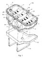
- the figure 1 illustrates a low engine module or oil sump module 100 composed of an upper shell 1 and a lower shell 2 assembled to one another.
- the oil sump 100 is intended to be fixed under the engine block 24 of an internal combustion engine, as illustrated in FIG. figure 6 .
- the Z axis is defined as the vertical axis, and the X, Y axes as defining a horizontal plane.
- the terms “superior”, “lower”, “high” and “low” are used in reference to the Z axis.
- the term “longitudinal” is used with reference to the Y axis, while the term “transverse” is used with reference to the X axis.
- the housing 100 is described in the position it occupies in the figures.
- the upper shell 1 incorporates various components necessary for the proper functioning of the device.
- the upper shell 1 is made in one piece by molding. It may for example be obtained by injection of a plastic material, by molding a thermosetting, or by molding aluminum. It comprises an upper wall 15 which forms an anti-emulsion plate 15 provided with orifices 27 permitting a first passage of the oil coming from the engine block 24 towards the interior volume of the casing 100.
- the upper shell 1 also comprises a peripheral wall 50 protruding from the periphery of the upper wall 15 and formed, in the embodiment shown, of four side walls. A second passage 23 of oil formed in the anti-emulsion plate 15, and which can follow one of said side walls, is directly connected with the bottom of the housing 100.
- the upper shell 1 further comprises an electric probe 6 and its fastening clip 7 for the purpose of informing the dashboard of a vehicle concerning the level, the temperature or the quality of the oil, an oil dipstick 8 and its housing 28 (illustrated in figure 2 ) for a control of the manual oil level, a plurality of perforations 26 on the upper edge of said upper shell 1 for fixing the oil sump 100 to the engine block 24, for example by screw spacers 12 (illustrated in FIG. figure 2 ).
- a seal 4 located on the upper edge of the upper shell 1 is intended to ensure a seal between the oil sump 100 and the engine block 24.
- fastening systems 17 disposed on either side of said upper shell 1 to allow the attachment of a piece 13 soundproofing and / or protection.
- the upper shell 1 has an element projecting from the upper wall 15 downwards (that is to say towards the inside of the casing 100 in the assembled position) and which forms an upper portion 21 of a strainer.
- the upper portion 21 of the strainer comprises a channel formed in the upper wall 15 of the upper shell 1, said channel being open downwards and opening outwardly of the housing 100 through an orifice formed in said upper wall 1 and surrounded by a substantially cylindrical portion forming the outlet
- the strainer outlet 19, with its gasket 5 makes it possible to raise the oil from the bottom of the casing 100 towards the various parts of the engine requiring lubrication, and also allows the centering of the casing 100 with respect to the engine block. 24 when mounting said housing 100.
- the integration of the upper portion of the strainer 21 to the upper shell 1 of the oil sump 100 is particularly shown in FIG. figures 3 and 6 .
- the anti-emulsion plate 15, the upper portion of the strainer 21 and the upper shell 1 form a single piece.
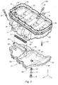
- the lower shell 2 is made in one piece by molding. It may for example be obtained by injection of a plastic material, by molding a thermosetting, or by molding aluminum. It comprises a bottom wall 51 and a peripheral wall 52 projecting from the periphery of the bottom wall 51 and formed, in the embodiment shown, of four side walls.
- the lower shell 2 has an element projecting from the bottom wall 51 upwards (that is to say towards the inside of the casing 100 in the assembled position) and which forms a lower portion 20 of a strainer.
- the lower portion 20 of the strainer comprises a channel 55 substantially horizontal and open at its upper part, supported by two feet 53, 54 protruding from the bottom wall 51.
- the foot 54 is hollow and has a notch 18 formed near the the bottom wall 51, so as to allow the suction of the oil from the interior of the lower shell 2 in said foot 54 to the channel 55.
- the notch 18 allows to calibrate and therefore control the flow of suction of oil into the strainer formed by the assembly of the lower portion 20 and the upper portion 21 of strainer. Furthermore, the notch 18 prevents any plugging of the strainer and thus to ensure a constant oil suction space.
- the lower portion of the strainer 20 and the lower shell 2 form a single piece.
- the lower shell 2 has on the outer face of its bottom wall 51 a series of ribs 16 oriented transversely and / or longitudinally, providing resistance to grit and impact.
- the bottom wall 54 further includes an orifice 29 for the evacuation of used oils.
- a plug closing orifice 29 is assembled on the lower shell 2, either directly or via a metal insert. Fixing the cap to the lower shell or the insert can be done either via a thread or via another solution for example a quarter-turn helical ramp.
- the seal is provided by a flat seal (axial seal) or preferably an O-ring (radial seal).
- This plug comprises a drain plug 9 and a seal 11. It may for example be composed of three parts, namely a drain plug 9, optionally an insert 10 - which can be threaded or not, which can be integral with the lower shell or a separate part - for fixing the plug and a seal 11 of drain plug.
- the lower shell 2 also has a wall 60 projecting from the bottom wall 54 inwards, and the function of which is to ensure an always sufficient oil level at the notch 18 for avoid drawing air into the strainer.
- This wall 60 - said anti-lift wall - is particularly useful during strong accelerations longitudinal (acceleration or braking) or transverse (right or left turns) during which the oil undergoes significant displacement.
- the lower and upper shells 1 and 2 are joined to each other along the free edge of their peripheral walls 52, 50, sealingly, thereby forming a housing. Simultaneously, the lower and upper portions 21 of strainer are assembled at their periphery, a screen 3 of mesh being trapped between said lower and upper portions 21.
- the assembly of the shells 1, 2, on the one hand, and portions 20, 21 of strainer, on the other hand, can be obtained by welding.
- the required rigidity of the oil sump 100 is obtained on the one hand by the fact that the strainer and the anti-emulsion plate are not inserts but integrated into the shells 1, 2.
- the strainer by the assembly of a lower portion 20 of integrated strainer to the lower shell 2 and an upper portion 21 of strainer integrated in the upper shell 1, the rigidity is further improved.
- a piece 13 soundproofing and / or protection is fixed under the lower shell 2 by fastening lugs 14 coming to mate with the attachment systems 17 formed on the upper shell 1.
- This part 13 which can be multilayer - for example a rubber layer and an absorbent layer (foam and / or fibrous) - produces a soundproofing effect and protection of the lower shell 2.
- said part 13 comprises an orifice 30 for the evacuation of used oils, for example during a drain, and arranged opposite the orifice 29of the lower shell 2.
- the figure 3 which is a longitudinal sectional view of the casing 100 showing the inside of the casing and the strainer, makes it possible to identify the points of contact between the lower and upper casing hulls 2 and 1 and those of the lower and upper portions 20 and 21 of the casing. the strainer. These contact points are the assembly areas of the housing 100. Said assembly zones are located along the periphery of the lower shell 2 and upper shell 1 as well as the periphery of the lower portions 20 and upper 21 of the strainer. Ideally and by way of example, the assembly is done by welding, the most suitable welding being the contactless infrared welding. This type of welding makes it possible to achieve a high level of cleanliness, this being a requirement for an oil circuit of an internal combustion engine.
- the infrared weld also makes it possible to effectively weld the internal profile at the level of the stiffeners (the borders of the periphery), which the vibration welding does not allow, for example, because of the almost total inaccessibility of this profile during the welding.
- the figures 4 and 5 illustrate the different paths that can take the oil from the engine block 24 and then move, by gravity or routing, in the bottom of the lower shell 2 of the housing 100.
- the figure 4 shows the passage or path S1 of the oil through the orifices 27 of the anti-emulsion plate 15 allowing a tasting flow to taste oil towards the bottom of the lower shell 2 of the casing 100.
- figure 5 illustrates a second path S2 or rather a pipe 23 for routing oil from the engine block 24 directly to the bottom of the lower shell 2 of the housing 100.
- the pipe 23 runs along the wall of the upper shell 1 to the bottom of the lower shell 2 of the housing 100.
- Path S1 is usually referred to as a main oil return circuit characterized by the natural runoff of the oil projected by the nozzles under the pistons.
- Path S2 is considered as a secondary circuit characterized by a channelized return of the oil from the cylinder head.
- the path S1 is taken by the oils coming from the low engine, for example the oils coming from the crankshaft / connecting rod interface as well as from the crankshaft bearing.
- the path S2 serves as a return circuit of the oils coming from the high engine and the engine center including the oils lubricating the camshaft, the valve stems but also the oils coming from the interface piston / cylinder and pistons / rods.
- the figure 6 shows schematically the integration of the anti-emulsion plate 15 and the upper portion 21 of the strainer to the upper shell 1, thus forming a single piece, and the integration of the lower portion 20 of the strainer to the lower shell 2, also forming a single piece.
- One of the essential points of the present invention is that the aforementioned elements are not reported but integrated.
- the figure 6 also shows the order of assembly of the main parts constituting the casing 100 according to the present invention.
- the lower shell 2 - incorporating the lower portion 20 of the strainer - is assembled to the upper shell 1 - integrating the upper portion 21 of the strainer and the anti-emulsion plate 15 -, trapping the screen grid 3.
- the casing thus formed is then attached to the engine block 24 by inserting an oil pan gasket 4.
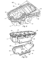
- FIGS. 7 and 8 illustrate a casing 100 according to a second embodiment of the invention.
- the oil sump 100 includes a housing for an oil filter 31, an oil cooler 32, and the associated oil circulation circuit.
- the oil filter and its housing 31 and the oil radiator 32 may be arranged either on the lower shell 2 or on the upper shell 1 of the housing 100.
- the oil collected in the casing 100, and more particularly in the lower shell 2 can then, before being conveyed to the engine, be treated, that is to say filtered and then cooled by following the following route: the oil is sucked through an oil pump (not shown) allowing it to escape from the oil sump through the strainer outlet 19 to be routed to an orifice 36 directly connected to the housing of the oil filter 31. Once filtered, the purified oil takes the line 41 leading to the oil radiator 32. The refined and hot oil then enters the radiator 32 through its inlet 40 for exit through the conduit 39 provided for this purpose. The filtered and cooled oil can finally be conveyed to the engine block 24 through the duct outlet 37.
- the supply of oil radiator 32 is provided by a water circuit comprising an inlet 34 and an outlet 33 for cooling the oil by heat exchange.
- the housing 100 has a reinforcement 35 provided on at least one of the outer sides of the casing 100, which ensures, in part, the fixing of the gearbox and a part of the force recovery on the motor block 24.
- This reinforcement 35 may be attached, in the case of a metal reinforcement, or integrated to the upper shell 1 in the case of a reinforcement obtained by plastic injection.
- the housing 100 includes a housing for oil filter 31 but no oil cooler.
- the oil is sucked through an oil pump allowing it to escape from the oil sump through the strainer outlet 19 to be routed to an orifice 36 directly connected to the housing of the oil filter 31.
- the purified oil takes the line 37 to be directly routed to the moving parts to lubricate the engine.
- the housing 100 illustrated on the figure 9 also comprises a reinforcement 35, similar to the housing illustrated on the Figures 7 and 8 .
- the reinforcement 35 is obtained by plastic injection and integrated into the upper shell 1 of the housing 100. It comprises a plurality of ribs 42 providing additional strength between the oil sump 100 and the gearbox.
- the top 1 and bottom 2 shells have corresponding lateral excrescences, which creates, in the assembled state, an additional lateral volume 22 in the casing 100.
- This additional lateral volume 22 accommodates a oil filter and / or an oil cooler and / or other components necessary for the proper operation of the oil circuit in the housing 100.
- At least one chimney 25 is integrated therein, in order to allow access to the fasteners of the lateral volume 22 by screws, but also to provide an additional reinforcing and structuring element of the casing 100 as a whole.
Landscapes
- Engineering & Computer Science (AREA)
- Mechanical Engineering (AREA)
- General Engineering & Computer Science (AREA)
- Lubrication Details And Ventilation Of Internal Combustion Engines (AREA)
- Filtration Of Liquid (AREA)
Claims (12)
- Ölwanne, die dazu bestimmt ist, an einem Motorblock (24) befestigt zu werden, ein unteres Gehäuse, einen Saugfilter und eine Antiemulsionsplatte umfassend, wobei:- das untere Gehäuse (2) ein Element umfasst, das einen unteren Abschnitt (20) des Saugfilters bildet, wobei das untere Gehäuse (2) und das besagte Element (20) mittels Formguss in einem Stück gefertigt sind;- die Wanne (100) darüber hinaus ein oberes Gehäuse (1) ein Element umfassend enthält, das einen oberen Abschnitt des Saugfilters (21) bildet, und eine Wand, die die Antiemulsionsplatte (15) bildet, wobei das obere Gehäuse (1), das besagte Element (21) und die Antiemulsionsplatte (15) mittels Formguss in einem Stück gefertigt sind;
das untere und das obere Gehäuse (2, 1) in dichter Form miteinander verbunden werden, um ein steifes Gehäuse zu bilden, wobei der untere Abschnitt und der obere Abschnitt (20, 21) des Saugfilters im zusammengebauten Zustand der Gehäuse in dichter Form miteinander verbunden sind, mit einem Gitter (3) dazwischen, um einen Saugfilter zu bilden, um das Öl zum Motor saugen zu können. - Ölwanne nach Anspruch 1, dadurch gekennzeichnet, dass das untere Gehäuse (2) eine Bodenwandung (51) und eine umlaufende Wand (52) umfasst, wobei der untere Abschnitt (20) des Saugfilters nach oben über die besagte Bodenwandung (51) übersteht, und dadurch, dass das obere Gehäuse (1) eine obere Wandung (15) und eine umlaufende Wand (50) umfasst, wobei der obere Abschnitt (21) des Saugfilters nach unten über die besagte obere Wandung (15) übersteht, wobei das untere und das obere Gehäuse (2, 1) an ihrem Umfang zusammengesetzt sind und der untere Abschnitt und der obere Abschnitt (20, 21) des Saugfilters ebenfalls an ihrem Umfang zusammengesetzt sind.
- Ölwanne nach Anspruch 1 oder 2, dadurch gekennzeichnet, dass der untere Abschnitt (20) des Saugfilters einen hohlen Fuß (54) umfasst, der aus einer Bodenwandung (51) des unteren Gehäuses (2) übersteht, wobei der besagte Fuß (54) zumindest eine Auskerbung (18) aufweist, die in der Nähe der besagten Bodenwandung (51) angeordnet ist, um das Ansaugen des Öls aus dem Innenvolumen des unteren Gehäuses (2) in den besagten Fuß (54) zu ermöglichen.
- Ölwanne nach einem der Ansprüche 1 bis 3, dadurch gekennzeichnet, dass der untere Abschnitt (20) des Saugfilters in seinem oberen Abschnitt einen offenen Kanal (55) umfasst, der von zwei Füßen (53, 54) getragen wird, die aus einer Bodenwandung (51) des unteren Gehäuses (2) überstehen, wobei zumindest ein Fuß (54) hohl ist und angeordnet ist, um das Ansaugen des Öls aus dem Innenvolumen des unteren Gehäuses (2) in den besagten Kanal (55) zu ermöglichen.
- Ölwanne nach einem der Ansprüche 1 bis 4, dadurch gekennzeichnet, dass der obere Abschnitt (21) des Saugfilters einen Kanal umfasst, der in einer oberen Wandung (15) des oberen Gehäuses (1) angeordnet ist, wobei der besagte Kanal nach unten offen ist und über eine Öffnung aus der Wanne (100) mündet, die in der besagten oberen Wandung angeordnet, und von einem in etwa zylindrischen Abschnitt umgeben ist, der den Saugfilterausgang (19) bildet.
- Ölwanne nach einem der Ansprüche 1 bis 5, dadurch gekennzeichnet, dass das obere Gehäuse (1) eine obere Wandung und eine umlaufende Wand (50) umfasst, wobei die obere Wandung die Antiemulsionsplatte (15) bildet.
- Ölwanne nach einem der Ansprüche 1 bis 6, dadurch gekennzeichnet, dass das untere Gehäuse (2) an seiner Außenseite mit Rippen (16) versehen ist, die dazu bestimmt sind, die Wanne (100) zu versteifen, und die Energie durch das Brechen der besagten Rippen bei einem Aufprall zu absorbieren.
- Ölwanne nach einem der Ansprüche 1 bis 7, dadurch gekennzeichnet, dass das obere Gehäuse (1) eine obere Wandung (15) aufweist, die an ihrem Umfang eine Vielzahl von Lochungen (26) aufweist, die die Befestigung der besagten Wanne (100) am Motorblock (24) unter Einbringung einer Dichtung ermöglichen.
- Ölwanne nach einem der Ansprüche 1 bis 8, dadurch gekennzeichnet, dass sie darüber hinaus ein Teil (13) zur Schalldämmung und/ oder Absorption von Stößen umfasst, das unter der besagten Wanne (100) beispielsweise durch Befestigungsmittel (14, 17) montiert ist, die mit zumindest einer der Außenflächen des unteren Gehäuses (2) der besagten Wanne (100) zusammenwirken.
- Ölwanne nach einem der Ansprüche 1 bis 9, dadurch gekennzeichnet, dass am oberen (1) oder am unteren (2) Gehäuse eine Aufnahme (28) eingearbeitet ist, um einen Ölmessstab (8) und/ oder eine elektrische Ölmess-Sonde (6) aufzunehmen.
- Ölwanne nach einem der Ansprüche 1 bis 10, dadurch gekennzeichnet, dass am oberen (1) oder am unteren (2) Gehäuse eine Aufnahme für einen Ölfilter angeordnet ist.
- Ölwanne nach einem der Ansprüche 1 bis 11, dadurch gekennzeichnet, dass am oberen (1) oder am unteren (2) Gehäuse Befestigungsmittel angeordnet sind, um einen Ölkühler aufzunehmen.
Applications Claiming Priority (2)
| Application Number | Priority Date | Filing Date | Title |
|---|---|---|---|
| FR1055038A FR2961859B1 (fr) | 2010-06-24 | 2010-06-24 | Carter d'huile destine a etre fixe a un bloc moteur |
| PCT/FR2011/050720 WO2011161339A1 (fr) | 2010-06-24 | 2011-03-31 | Carter d'huile destine a etre fixe a un bloc moteur |
Publications (3)
| Publication Number | Publication Date |
|---|---|
| EP2585689A1 EP2585689A1 (de) | 2013-05-01 |
| EP2585689B1 true EP2585689B1 (de) | 2015-12-30 |
| EP2585689B8 EP2585689B8 (de) | 2016-04-13 |
Family
ID=43032829
Family Applications (1)
| Application Number | Title | Priority Date | Filing Date |
|---|---|---|---|
| EP11717306.2A Active EP2585689B8 (de) | 2010-06-24 | 2011-03-31 | Ölwanne für die befestigung an einem motorblock |
Country Status (6)
| Country | Link |
|---|---|
| EP (1) | EP2585689B8 (de) |
| CN (1) | CN102947557B (de) |
| BR (1) | BR112012031428A2 (de) |
| ES (1) | ES2564990T3 (de) |
| FR (1) | FR2961859B1 (de) |
| WO (1) | WO2011161339A1 (de) |
Cited By (2)
| Publication number | Priority date | Publication date | Assignee | Title |
|---|---|---|---|---|
| EP4407150A1 (de) * | 2023-01-24 | 2024-07-31 | Schwäbische Hüttenwerke Automotive GmbH | Ölwanne, insbesondere ölfiltermodul, mit einem mehrteiligen gehäuse |
| US12535022B2 (en) | 2023-01-24 | 2026-01-27 | Schwäbische Hüttenwerke Automotive GmbH | Oil sump, in particular oil filter module, with a multi-part housing |
Families Citing this family (5)
| Publication number | Priority date | Publication date | Assignee | Title |
|---|---|---|---|---|
| FR2969695B1 (fr) * | 2010-12-23 | 2012-12-21 | Renault Sa | Carter d'huile pour moteur thermique |
| FR3016405B1 (fr) * | 2014-01-14 | 2016-02-12 | Cera | Systeme de montage d’un capot d’insonorisation sous un element de moteur de vehicule automobile |
| CN106499462B (zh) * | 2016-12-27 | 2022-04-08 | 张明 | 汽车气门室机油防乳化系统 |
| FR3119417B1 (fr) | 2021-02-02 | 2023-12-29 | Renault Sas | Plaque anti-émulsion avec passage gaz blow-by |
| US12492651B2 (en) * | 2024-04-30 | 2025-12-09 | WAL Fuel Systems USA Inc. | Non-metallic lubricant pan for a vehicle including a structural reinforcement member |
Family Cites Families (8)
| Publication number | Priority date | Publication date | Assignee | Title |
|---|---|---|---|---|
| DE3830966C1 (de) * | 1988-09-12 | 1989-05-11 | Dr.Ing.H.C. F. Porsche Ag, 7000 Stuttgart, De | |
| JPH10196341A (ja) * | 1997-01-13 | 1998-07-28 | Nissan Motor Co Ltd | 内燃機関におけるオイルパンの制振構造 |
| US6705270B1 (en) | 2000-04-26 | 2004-03-16 | Basf Corporation | Oil pan module for internal combustion engines |
| FR2849467B1 (fr) * | 2002-12-27 | 2007-01-26 | Renault Sa | Plaque anti-emulsion pour rigidifier les parois d'un carter d'huile de vehicule automobile |
| FR2900687B1 (fr) * | 2006-05-04 | 2008-07-04 | Mann & Hummel Gmbh | Carter d'huile pour moteur a combustion interne |
| DE102008027662A1 (de) * | 2008-06-10 | 2009-12-17 | Ibs Filtran Kunststoff- / Metallerzeugnisse Gmbh | Ölwanne mit Ölfilter |
| DE102008048793A1 (de) * | 2008-09-24 | 2010-03-25 | Mann + Hummel Gmbh | Verfahren zur Herstellung einer Kunststoffölwanne mittels Heißgasschweißen |
| DE102009059708A1 (de) * | 2008-12-26 | 2010-07-01 | Daikyonishikawa Corp. | Ölwanne |
-
2010
- 2010-06-24 FR FR1055038A patent/FR2961859B1/fr not_active Expired - Fee Related
-
2011
- 2011-03-31 ES ES11717306.2T patent/ES2564990T3/es active Active
- 2011-03-31 BR BR112012031428A patent/BR112012031428A2/pt not_active IP Right Cessation
- 2011-03-31 WO PCT/FR2011/050720 patent/WO2011161339A1/fr not_active Ceased
- 2011-03-31 EP EP11717306.2A patent/EP2585689B8/de active Active
- 2011-03-31 CN CN201180028957.1A patent/CN102947557B/zh not_active Expired - Fee Related
Cited By (2)
| Publication number | Priority date | Publication date | Assignee | Title |
|---|---|---|---|---|
| EP4407150A1 (de) * | 2023-01-24 | 2024-07-31 | Schwäbische Hüttenwerke Automotive GmbH | Ölwanne, insbesondere ölfiltermodul, mit einem mehrteiligen gehäuse |
| US12535022B2 (en) | 2023-01-24 | 2026-01-27 | Schwäbische Hüttenwerke Automotive GmbH | Oil sump, in particular oil filter module, with a multi-part housing |
Also Published As
| Publication number | Publication date |
|---|---|
| FR2961859B1 (fr) | 2012-07-06 |
| CN102947557B (zh) | 2016-03-30 |
| ES2564990T3 (es) | 2016-03-30 |
| EP2585689A1 (de) | 2013-05-01 |
| BR112012031428A2 (pt) | 2016-11-08 |
| WO2011161339A1 (fr) | 2011-12-29 |
| CN102947557A (zh) | 2013-02-27 |
| EP2585689B8 (de) | 2016-04-13 |
| FR2961859A1 (fr) | 2011-12-30 |
Similar Documents
| Publication | Publication Date | Title |
|---|---|---|
| EP2585689B1 (de) | Bac d'huile par un moteur | |
| FR2715191A1 (fr) | Combinaison filtre à huile-radiateur d'huile dans un couvercle de carter de moteur à combustion interne. | |
| FR2764642A1 (fr) | Carter d'huile pour moteurs ou engrenages | |
| EP3529467B1 (de) | Ölwanne | |
| WO2012085441A1 (fr) | Carter d'huile pour moteur thermique | |
| FR3035336A1 (fr) | Dispositif et agencement a element filtrant pour separer l'huile des gaz de carter d'un moteur a combustion interne | |
| JP6208556B2 (ja) | オイルストレーナおよび車両のオイル貯留装置 | |
| FR3078293A1 (fr) | Groupe motopropulseur de vehicule a machine electrique motrice suspendue a une traverse hybride a pieces de filtrage | |
| FR2900687A1 (fr) | Carter d'huile pour moteur a combustion interne | |
| FR3073042A1 (fr) | Echangeur de chaleur pour moteurs a combustion interne | |
| EP3394556B1 (de) | Gas-wärmetauscher, insbesondere für motorabgas, und gasleitungseinheit mit partikelfilter | |
| WO2018020112A1 (fr) | Berceau pour turbopropulseur a manche d'entrée d'air intégrée | |
| FR2976233A1 (fr) | Systeme de fixation d'une batterie | |
| FR3001997A1 (fr) | Filtre a huile | |
| FR2985769A1 (fr) | Bloc-moteur d'un moteur a combustion interne | |
| WO2006095104A1 (fr) | Dispositif de circulation d'huile pour moteur a combustion interne | |
| FR2764636A1 (fr) | Cartouche de filtre a huile pour carters d'huile de moteurs ou d'engrenages | |
| BE1029751B1 (fr) | Dispositif désaérateur d’huile avec reservoir pourvu d’une paroi de stabilisation | |
| WO2012150397A2 (fr) | Reservoir de carburant pour moteur diesel | |
| FR2992362A1 (fr) | Carter cylindres et carter d'huile associe pour moteur thermique | |
| EP1227237B1 (de) | Zylinderkopf für eine Brennkraftmaschine mit einem Ventilierungskanal | |
| EP2039895B1 (de) | Strukturelle Ölwanne aus Plastik mit Einsatzboden für Verbrennungsmotor und Herstellungsverfahren einer solchen Wanne | |
| EP2955050B1 (de) | Hinterachse eines kraftfahrzeugs, die mit einem in eine querachse integrierten auspufftopf ausgestattet ist | |
| EP2722257B1 (de) | Wasserkastenmodul | |
| WO2022167293A1 (fr) | Plaque anti-émulsion avec passage gaz blow-by |
Legal Events
| Date | Code | Title | Description |
|---|---|---|---|
| PUAI | Public reference made under article 153(3) epc to a published international application that has entered the european phase |
Free format text: ORIGINAL CODE: 0009012 |
|
| 17P | Request for examination filed |
Effective date: 20121126 |
|
| AK | Designated contracting states |
Kind code of ref document: A1 Designated state(s): AL AT BE BG CH CY CZ DE DK EE ES FI FR GB GR HR HU IE IS IT LI LT LU LV MC MK MT NL NO PL PT RO RS SE SI SK SM TR |
|
| DAX | Request for extension of the european patent (deleted) | ||
| GRAJ | Information related to disapproval of communication of intention to grant by the applicant or resumption of examination proceedings by the epo deleted |
Free format text: ORIGINAL CODE: EPIDOSDIGR1 |
|
| GRAP | Despatch of communication of intention to grant a patent |
Free format text: ORIGINAL CODE: EPIDOSNIGR1 |
|
| INTG | Intention to grant announced |
Effective date: 20150717 |
|
| GRAS | Grant fee paid |
Free format text: ORIGINAL CODE: EPIDOSNIGR3 |
|
| GRAA | (expected) grant |
Free format text: ORIGINAL CODE: 0009210 |
|
| RAP1 | Party data changed (applicant data changed or rights of an application transferred) |
Owner name: MECAPLAST DIFFUSION |
|
| AK | Designated contracting states |
Kind code of ref document: B1 Designated state(s): AL AT BE BG CH CY CZ DE DK EE ES FI FR GB GR HR HU IE IS IT LI LT LU LV MC MK MT NL NO PL PT RO RS SE SI SK SM TR |
|
| REG | Reference to a national code |
Ref country code: GB Ref legal event code: FG4D Free format text: NOT ENGLISH |
|
| REG | Reference to a national code |
Ref country code: CH Ref legal event code: EP |
|
| RAP2 | Party data changed (patent owner data changed or rights of a patent transferred) |
Owner name: MECAPLAST FRANCE |
|
| REG | Reference to a national code |
Ref country code: AT Ref legal event code: REF Ref document number: 767597 Country of ref document: AT Kind code of ref document: T Effective date: 20160115 |
|
| REG | Reference to a national code |
Ref country code: IE Ref legal event code: FG4D Free format text: LANGUAGE OF EP DOCUMENT: FRENCH |
|
| REG | Reference to a national code |
Ref country code: DE Ref legal event code: R096 Ref document number: 602011022250 Country of ref document: DE |
|
| GRAT | Correction requested after decision to grant or after decision to maintain patent in amended form |
Free format text: ORIGINAL CODE: EPIDOSNCDEC |
|
| REG | Reference to a national code |
Ref country code: FR Ref legal event code: PLFP Year of fee payment: 6 |
|
| REG | Reference to a national code |
Ref country code: ES Ref legal event code: FG2A Ref document number: 2564990 Country of ref document: ES Kind code of ref document: T3 Effective date: 20160330 |
|
| REG | Reference to a national code |
Ref country code: LT Ref legal event code: MG4D |
|
| PG25 | Lapsed in a contracting state [announced via postgrant information from national office to epo] |
Ref country code: NO Free format text: LAPSE BECAUSE OF FAILURE TO SUBMIT A TRANSLATION OF THE DESCRIPTION OR TO PAY THE FEE WITHIN THE PRESCRIBED TIME-LIMIT Effective date: 20160330 Ref country code: HR Free format text: LAPSE BECAUSE OF FAILURE TO SUBMIT A TRANSLATION OF THE DESCRIPTION OR TO PAY THE FEE WITHIN THE PRESCRIBED TIME-LIMIT Effective date: 20151230 Ref country code: LT Free format text: LAPSE BECAUSE OF FAILURE TO SUBMIT A TRANSLATION OF THE DESCRIPTION OR TO PAY THE FEE WITHIN THE PRESCRIBED TIME-LIMIT Effective date: 20151230 |
|
| REG | Reference to a national code |
Ref country code: NL Ref legal event code: MP Effective date: 20151230 |
|
| REG | Reference to a national code |
Ref country code: AT Ref legal event code: MK05 Ref document number: 767597 Country of ref document: AT Kind code of ref document: T Effective date: 20151230 |
|
| PG25 | Lapsed in a contracting state [announced via postgrant information from national office to epo] |
Ref country code: LV Free format text: LAPSE BECAUSE OF FAILURE TO SUBMIT A TRANSLATION OF THE DESCRIPTION OR TO PAY THE FEE WITHIN THE PRESCRIBED TIME-LIMIT Effective date: 20151230 Ref country code: FI Free format text: LAPSE BECAUSE OF FAILURE TO SUBMIT A TRANSLATION OF THE DESCRIPTION OR TO PAY THE FEE WITHIN THE PRESCRIBED TIME-LIMIT Effective date: 20151230 Ref country code: RS Free format text: LAPSE BECAUSE OF FAILURE TO SUBMIT A TRANSLATION OF THE DESCRIPTION OR TO PAY THE FEE WITHIN THE PRESCRIBED TIME-LIMIT Effective date: 20151230 Ref country code: SE Free format text: LAPSE BECAUSE OF FAILURE TO SUBMIT A TRANSLATION OF THE DESCRIPTION OR TO PAY THE FEE WITHIN THE PRESCRIBED TIME-LIMIT Effective date: 20151230 Ref country code: GR Free format text: LAPSE BECAUSE OF FAILURE TO SUBMIT A TRANSLATION OF THE DESCRIPTION OR TO PAY THE FEE WITHIN THE PRESCRIBED TIME-LIMIT Effective date: 20160331 |
|
| PG25 | Lapsed in a contracting state [announced via postgrant information from national office to epo] |
Ref country code: NL Free format text: LAPSE BECAUSE OF FAILURE TO SUBMIT A TRANSLATION OF THE DESCRIPTION OR TO PAY THE FEE WITHIN THE PRESCRIBED TIME-LIMIT Effective date: 20151230 |
|
| PG25 | Lapsed in a contracting state [announced via postgrant information from national office to epo] |
Ref country code: RO Free format text: LAPSE BECAUSE OF FAILURE TO SUBMIT A TRANSLATION OF THE DESCRIPTION OR TO PAY THE FEE WITHIN THE PRESCRIBED TIME-LIMIT Effective date: 20151230 Ref country code: AT Free format text: LAPSE BECAUSE OF FAILURE TO SUBMIT A TRANSLATION OF THE DESCRIPTION OR TO PAY THE FEE WITHIN THE PRESCRIBED TIME-LIMIT Effective date: 20151230 Ref country code: BE Free format text: LAPSE BECAUSE OF NON-PAYMENT OF DUE FEES Effective date: 20160331 Ref country code: SM Free format text: LAPSE BECAUSE OF FAILURE TO SUBMIT A TRANSLATION OF THE DESCRIPTION OR TO PAY THE FEE WITHIN THE PRESCRIBED TIME-LIMIT Effective date: 20151230 Ref country code: PL Free format text: LAPSE BECAUSE OF FAILURE TO SUBMIT A TRANSLATION OF THE DESCRIPTION OR TO PAY THE FEE WITHIN THE PRESCRIBED TIME-LIMIT Effective date: 20151230 Ref country code: IS Free format text: LAPSE BECAUSE OF FAILURE TO SUBMIT A TRANSLATION OF THE DESCRIPTION OR TO PAY THE FEE WITHIN THE PRESCRIBED TIME-LIMIT Effective date: 20160430 Ref country code: SK Free format text: LAPSE BECAUSE OF FAILURE TO SUBMIT A TRANSLATION OF THE DESCRIPTION OR TO PAY THE FEE WITHIN THE PRESCRIBED TIME-LIMIT Effective date: 20151230 Ref country code: EE Free format text: LAPSE BECAUSE OF FAILURE TO SUBMIT A TRANSLATION OF THE DESCRIPTION OR TO PAY THE FEE WITHIN THE PRESCRIBED TIME-LIMIT Effective date: 20151230 |
|
| REG | Reference to a national code |
Ref country code: DE Ref legal event code: R097 Ref document number: 602011022250 Country of ref document: DE |
|
| PG25 | Lapsed in a contracting state [announced via postgrant information from national office to epo] |
Ref country code: LU Free format text: LAPSE BECAUSE OF FAILURE TO SUBMIT A TRANSLATION OF THE DESCRIPTION OR TO PAY THE FEE WITHIN THE PRESCRIBED TIME-LIMIT Effective date: 20160331 Ref country code: DK Free format text: LAPSE BECAUSE OF FAILURE TO SUBMIT A TRANSLATION OF THE DESCRIPTION OR TO PAY THE FEE WITHIN THE PRESCRIBED TIME-LIMIT Effective date: 20151230 Ref country code: MC Free format text: LAPSE BECAUSE OF FAILURE TO SUBMIT A TRANSLATION OF THE DESCRIPTION OR TO PAY THE FEE WITHIN THE PRESCRIBED TIME-LIMIT Effective date: 20151230 |
|
| REG | Reference to a national code |
Ref country code: CH Ref legal event code: PL |
|
| PLBE | No opposition filed within time limit |
Free format text: ORIGINAL CODE: 0009261 |
|
| STAA | Information on the status of an ep patent application or granted ep patent |
Free format text: STATUS: NO OPPOSITION FILED WITHIN TIME LIMIT |
|
| GBPC | Gb: european patent ceased through non-payment of renewal fee |
Effective date: 20160331 |
|
| 26N | No opposition filed |
Effective date: 20161003 |
|
| REG | Reference to a national code |
Ref country code: IE Ref legal event code: MM4A |
|
| PG25 | Lapsed in a contracting state [announced via postgrant information from national office to epo] |
Ref country code: LI Free format text: LAPSE BECAUSE OF NON-PAYMENT OF DUE FEES Effective date: 20160331 Ref country code: GB Free format text: LAPSE BECAUSE OF NON-PAYMENT OF DUE FEES Effective date: 20160331 Ref country code: IE Free format text: LAPSE BECAUSE OF NON-PAYMENT OF DUE FEES Effective date: 20160331 Ref country code: CH Free format text: LAPSE BECAUSE OF NON-PAYMENT OF DUE FEES Effective date: 20160331 |
|
| PG25 | Lapsed in a contracting state [announced via postgrant information from national office to epo] |
Ref country code: SI Free format text: LAPSE BECAUSE OF FAILURE TO SUBMIT A TRANSLATION OF THE DESCRIPTION OR TO PAY THE FEE WITHIN THE PRESCRIBED TIME-LIMIT Effective date: 20151230 |
|
| REG | Reference to a national code |
Ref country code: FR Ref legal event code: PLFP Year of fee payment: 7 |
|
| PG25 | Lapsed in a contracting state [announced via postgrant information from national office to epo] |
Ref country code: MT Free format text: LAPSE BECAUSE OF FAILURE TO SUBMIT A TRANSLATION OF THE DESCRIPTION OR TO PAY THE FEE WITHIN THE PRESCRIBED TIME-LIMIT Effective date: 20151230 |
|
| REG | Reference to a national code |
Ref country code: FR Ref legal event code: PLFP Year of fee payment: 8 |
|
| REG | Reference to a national code |
Ref country code: FR Ref legal event code: CD Owner name: NOVARES FRANCE, FR Effective date: 20180412 |
|
| PG25 | Lapsed in a contracting state [announced via postgrant information from national office to epo] |
Ref country code: CY Free format text: LAPSE BECAUSE OF FAILURE TO SUBMIT A TRANSLATION OF THE DESCRIPTION OR TO PAY THE FEE WITHIN THE PRESCRIBED TIME-LIMIT Effective date: 20151230 Ref country code: HU Free format text: LAPSE BECAUSE OF FAILURE TO SUBMIT A TRANSLATION OF THE DESCRIPTION OR TO PAY THE FEE WITHIN THE PRESCRIBED TIME-LIMIT; INVALID AB INITIO Effective date: 20110331 |
|
| PG25 | Lapsed in a contracting state [announced via postgrant information from national office to epo] |
Ref country code: PT Free format text: LAPSE BECAUSE OF FAILURE TO SUBMIT A TRANSLATION OF THE DESCRIPTION OR TO PAY THE FEE WITHIN THE PRESCRIBED TIME-LIMIT Effective date: 20151230 Ref country code: MK Free format text: LAPSE BECAUSE OF FAILURE TO SUBMIT A TRANSLATION OF THE DESCRIPTION OR TO PAY THE FEE WITHIN THE PRESCRIBED TIME-LIMIT Effective date: 20151230 |
|
| PG25 | Lapsed in a contracting state [announced via postgrant information from national office to epo] |
Ref country code: BG Free format text: LAPSE BECAUSE OF FAILURE TO SUBMIT A TRANSLATION OF THE DESCRIPTION OR TO PAY THE FEE WITHIN THE PRESCRIBED TIME-LIMIT Effective date: 20151230 |
|
| PG25 | Lapsed in a contracting state [announced via postgrant information from national office to epo] |
Ref country code: AL Free format text: LAPSE BECAUSE OF FAILURE TO SUBMIT A TRANSLATION OF THE DESCRIPTION OR TO PAY THE FEE WITHIN THE PRESCRIBED TIME-LIMIT Effective date: 20151230 |
|
| REG | Reference to a national code |
Ref country code: ES Ref legal event code: PC2A Owner name: NOVARES FRANCE Effective date: 20200203 |
|
| REG | Reference to a national code |
Ref country code: DE Ref legal event code: R082 Ref document number: 602011022250 Country of ref document: DE Ref country code: DE Ref legal event code: R081 Ref document number: 602011022250 Country of ref document: DE Owner name: NOVARES FRANCE, FR Free format text: FORMER OWNER: MECAPLAST FRANCE, CLAMART, FR |
|
| PGFP | Annual fee paid to national office [announced via postgrant information from national office to epo] |
Ref country code: CZ Payment date: 20230314 Year of fee payment: 13 |
|
| PGFP | Annual fee paid to national office [announced via postgrant information from national office to epo] |
Ref country code: TR Payment date: 20230320 Year of fee payment: 13 Ref country code: IT Payment date: 20230314 Year of fee payment: 13 Ref country code: DE Payment date: 20230316 Year of fee payment: 13 |
|
| PGFP | Annual fee paid to national office [announced via postgrant information from national office to epo] |
Ref country code: ES Payment date: 20230414 Year of fee payment: 13 |
|
| REG | Reference to a national code |
Ref country code: DE Ref legal event code: R119 Ref document number: 602011022250 Country of ref document: DE |
|
| PG25 | Lapsed in a contracting state [announced via postgrant information from national office to epo] |
Ref country code: CZ Free format text: LAPSE BECAUSE OF NON-PAYMENT OF DUE FEES Effective date: 20240331 |
|
| PG25 | Lapsed in a contracting state [announced via postgrant information from national office to epo] |
Ref country code: CZ Free format text: LAPSE BECAUSE OF NON-PAYMENT OF DUE FEES Effective date: 20240331 |
|
| PG25 | Lapsed in a contracting state [announced via postgrant information from national office to epo] |
Ref country code: DE Free format text: LAPSE BECAUSE OF NON-PAYMENT OF DUE FEES Effective date: 20241001 |
|
| PG25 | Lapsed in a contracting state [announced via postgrant information from national office to epo] |
Ref country code: DE Free format text: LAPSE BECAUSE OF NON-PAYMENT OF DUE FEES Effective date: 20241001 |
|
| PG25 | Lapsed in a contracting state [announced via postgrant information from national office to epo] |
Ref country code: IT Free format text: LAPSE BECAUSE OF NON-PAYMENT OF DUE FEES Effective date: 20240331 |
|
| REG | Reference to a national code |
Ref country code: ES Ref legal event code: FD2A Effective date: 20250508 |
|
| PG25 | Lapsed in a contracting state [announced via postgrant information from national office to epo] |
Ref country code: ES Free format text: LAPSE BECAUSE OF NON-PAYMENT OF DUE FEES Effective date: 20240401 |
|
| PGFP | Annual fee paid to national office [announced via postgrant information from national office to epo] |
Ref country code: FR Payment date: 20260330 Year of fee payment: 16 |