EP3722473B1 - Dispositif de préhension d'un dispositif destiné à l'introduction des éléments d'insertion dans un tricot - Google Patents
Dispositif de préhension d'un dispositif destiné à l'introduction des éléments d'insertion dans un tricot Download PDFInfo
- Publication number
- EP3722473B1 EP3722473B1 EP19167876.2A EP19167876A EP3722473B1 EP 3722473 B1 EP3722473 B1 EP 3722473B1 EP 19167876 A EP19167876 A EP 19167876A EP 3722473 B1 EP3722473 B1 EP 3722473B1
- Authority
- EP
- European Patent Office
- Prior art keywords
- gripping
- gripper
- knitted fabric
- insert
- knitting machine
- Prior art date
- Legal status (The legal status is an assumption and is not a legal conclusion. Google has not performed a legal analysis and makes no representation as to the accuracy of the status listed.)
- Active
Links
Images

Classifications
-
- D—TEXTILES; PAPER
- D04—BRAIDING; LACE-MAKING; KNITTING; TRIMMINGS; NON-WOVEN FABRICS
- D04B—KNITTING
- D04B15/00—Details of, or auxiliary devices incorporated in, weft knitting machines, restricted to machines of this kind
Definitions
- the producing knitting machine When introducing the knitted fabric during production, however, the producing knitting machine must be permanently monitored by personnel, since the knitting machine stops at the point in time at which the additional element is inserted, i.e. the production of the knitted fabric is interrupted. The result is an increased workforce.
- the US 7 246 508 B1 describes a device for inserting elements for stabilizing the shape of the collar on a knitted fabric such as a jacket made on a flat knitting machine.
- a stack of collar inserts is motorized together with a slider along the flat knitting machine above the needle beds until the insertion position in the knitted fabric is reached and one of the collar inserts can be inserted into the knitted fabric through the slider.
- the DE 43 08 251 C2 shows a self-sufficient functional element which can be used, among other things, to insert additional elements into the knitted fabric.
- This functional element is attached to the thread guide rails and therefore reduces the possible number of thread guides involved in the knitting process. In addition, the functional element hinders the movement of the thread guides, since it is always in the same area as the thread guides.
- the present invention therefore has the object of developing a gripping device of a device for inserting inserts of a flat knitting machine in such a way that the disadvantages described in the prior art are avoided and reliable insertion of the insert into the knitted fabric is ensured.
- the object is achieved by a gripping device of a device on a flat knitting machine for inserting inserts into a knitted fabric produced on the flat knitting machine with the features of claim 1.
- the gripping device can be arranged on the slide of the flat knitting machine or have a separate drive for movement along the machine.
- the function of thread guides and the actual knitting process are not hindered by the gripping device when it is not needed.
- the magazine can be a device that is independent of the knitting machine and is arranged next to the knitting machine, or it can be arranged on the knitting machine, both a stationary arrangement and an arrangement movable along the machine being possible.
- the gripping device is independent of the design of the magazine. Adjustments to different magazines are possible by changing the control of the gripping device.
- the gripping device has a gripper with at least one movable gripping jaw.
- the gripper is thus able to securely pick up differently shaped and differently sized inserts and to transport them to a pick-up area of the knitted fabric produced on the knitting machine.
- the gripping jaws can have a contoured surface and / or be made of a material with good holding power. This ensures that the inserts are held securely even when the gripper moves quickly.
- materials for the gripping jaws or at least their surface non-magnetic materials for magnetic inserts or materials with a good holding force such as plastic or rubber come into question.
- insert parts such as batteries, LEDs, sensors or the like can be safely taken from the magazine and inserted into the knitted fabric.
- the gripper can be moved by a motor at least between a rest position that does not impede the knitting process and an insertion position. If the magazine is stationary on the machine and / or has no transfer devices to the gripper and / or if it is a separate device, a third position is required for the gripper in which it is able to remove an insert from the magazine refer to.
- the inserts can be moved with the gripper to below the needle cross of the flat knitting machine.
- the pockets or other receptacles of the knitted fabric for the inserts are completed before the inserts are inserted. Therefore, the openings of the receptacles are also located below the needle cross. If the gripper is able to press the insert parts below the needle cross, the insert parts can be safely and completely inserted into the knitted fabric receptacles.
- the gripper also has an ejection device for releasing and / or positioning the inserts in the knitted fabric.
- an ejection device supports the delivery of the inserts after the gripping jaws have been opened.
- the ejection device can preferably have an ejector which can be retracted and extended, with which an insert part held by the gripping jaws can be moved into a receiving area of the knitted fabric after the gripping jaws have been opened.
- the receiving area can, for example, be a pocket knitted into the knitted fabric.
- the opening of the pocket below the ridge gap of the machine is quite narrow, so that it is advantageous to apply a positive force to insert the insert through the ejector.
- the ejection ram can be extended to different extents, so that insert parts of different sizes can be moved with its help to below the needle cross of the flat knitting machine.
- the gripping device can thus be adjusted to different insert parts.
- the gripper in its insertion position and with the ejector ram extended, can be moved by the slide over the insertion part in order to reach into the receiving area of the knitted fabric.
- This measure is particularly advantageous when inserting long inserts into the knitted fabric.
- the ejection ram acts on the entire upper edge of the insert and thus reliably presses it into the receiving area of the knitted fabric.
- the gripping device can have monitoring devices with which the presence and the position of an insert part in the gripper and the comb gap can be monitored.
- Optical or capacitive sensors in particular can be used for this purpose. If there is no insert between the gripper jaws, a new one must be picked up from the magazine. The ridge gap must be completely open, ie all needles and sinkers must be withdrawn. Otherwise, the attempt to insert the insert through the gripping device would lead to damage to the needles or sinkers. If the ridge gap is not completely free, the insertion of the insert is therefore stopped and an error message is output.
- the gripping device For the actuation of the different functions of the gripping device, it can preferably have a first motor for moving the gripper and a second motor for moving the gripping jaws and the ejecting device.
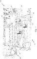
- Fig. 1 shows a schematic view of the partial area of a known flat knitting machine 100 with a front and rear needle bed, not shown here.
- a front and rear carriage 20, 20 ', to which knitting locks 30, 30' are attached, is moved over the needle beds.
- the flat knitting machine 100 has a device 10 for inserting insert parts 70 ( Figure 4b ) into a knitted fabric produced on the flat knitting machine, which is formed by a magazine 40 for inserts 70, which is rigidly arranged to the left of the needle beds (not shown here), and a gripping device 50 for inserts 70.
- the magazine 40 is designed for storing and dispensing the inserts 70, which for this purpose are stored in a magazine container 41 and, if necessary, can be dispensed by means of a transport device not shown in detail here.
- a defined delivery position of the inserts 70 can be approached with the transport device. This defined delivery position can be adapted in accordance with the possible different dimensions of the insert parts 70 to be fed.
- Sensors are also provided which monitor the presence of insert parts 70, their position in the magazine container 41 and the position of the transport device.
- the transport device can, for example, have a slide element which brings the respective insert 70 into a predetermined position for reception by a gripper of a device for inserting an insert 70.
- the introduction of movement into the slide can be done by a motor using a gear unit, toothed rack, belt drive, etc.
- An NFC writer 47 is also attached to the magazine 40, which makes it possible to transfer data to microchips integrated in the insert 70.
- the gripping device 50 is attached to the side of the slide 20 and is therefore moved along with it.
- the gripping device 50 takes over the inserts 70 brought by the magazine 40 into the defined delivery position from the magazine 40 and introduces them into a predefined receiving area within a knitted piece (not shown here) which is currently being produced on the flat knitting machine 100.
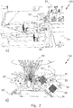
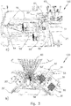
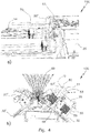
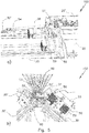
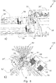
- FIGS. 2a-6b show a schematic view of the process of inserting an insert 70 by the gripping device 50, each based on a perspective view (a) and a section (b) through the flat knitting machine 100, starting in the rest position of the gripper 51 of the gripping device 50.
- the Fig. 2a, b show the gripping device 50 with a gripper 51, the gripper 51 being in a rest position. For this purpose, it is pivoted into a rear end position. In this position, the gripper 51 cannot collide with elements such as thread guides 60 etc. when the carriage 20, 20 'executes movements over the needle beds to act on elements necessary for knitting, such as needles or sinkers.
- the gripper 51 of the gripping device 50 moves from its rear end position or rest position, driven by a first motor 58, into a vertical position in which the insert 70 is securely gripped can.
- the gripping jaws 52, 52 ′ of the gripper 51 driven by a second motor 59, move away from one another and thus free a space for receiving the insert 70.
- the opposite gripping jaw 52 is rigid. But it is also conceivable to move both gripping jaws 52, 52 '.
- Fig. 4a, b show a view in which the insert 70 is moved into a defined receiving position between the gripping jaws 52, 52 'by the feed devices of the magazine 40, not shown here and the gripping jaws 52, 52 'were moved towards one another by means of the second motor 59 and thus keep the insert 70 clamped between them.
- Fig. 5a, b the gripping device 50 is shown after the carriage 20, 20 'has been moved over the knitting area of the flat knitting machine 100 to a position at which the insert 70, which is held between the gripping jaws 52, 52' of the gripper 51, into the formed knitted fabric should be inserted.
- a pocket can be formed as a receiving area for the insert 70 in the knitted fabric.
- the movement is a pivoting movement, initiated by the first motor 58.
- the movement can alternatively also be carried out linearly or in any combination of rotational and linear movements .
- the insert 70 is inserted into the pocket formed in the previous knitting process.
- Fig. 6a, b show a view of the gripping device 50 after the gripping jaws 52, 52 'have been opened by means of the second motor 59 and, likewise by means of the second motor 59, an ejection device 53 on the gripper 51 has been moved from an upper rest position in the direction of the comb gap 80 into an ejection position .
- This movement of the ejection device 53 moves the insert 70 out of the area between the gripping jaws 52, 52 'and into the receiving area of the knitted fabric.
- the carriage 20, 20 ′ is then moved in the direction of the magazine 40 counter to its previous knitting direction.
- the gripper 51 and the ejector 53 remain in their in the Figure 6a , b positions shown.
- the insert 70 is securely slipped into the knitted fabric.
- the knitting process for the knitted fabric can be resumed.
- the pocket into which the insert 70 was placed can be partially or completely closed.
- Fig. 7 illustrates the structure of the gripping device 50 in an individual illustration with partially omitted or cut-open housing parts.
- the displaceable arrangement of the gripping device 50 on a guide 25 for the slide 20, 20 '(not shown here) can be seen.
- the pivoting movement of the gripper 51 in the direction of the double arrow 54 is brought about by the motor 58.
- the lower, movable clamping jaw 52 ′ is pressed against the stationary gripping jaw 52 by a spring 55.
- the opening movement of the gripping jaw 52 ′ is triggered by the second motor 59.
- This motor 59 also moves the ejector 53 back and forth via a lever mechanism 56.
- the transmission of the force between motor 59 and lever mechanism 56 takes place via a toothed belt 57.
- the ejection device 53 has an ejection ram 53 'which protrudes between the gripping jaws 52, 52' and can be moved back and forth.
Landscapes
- Engineering & Computer Science (AREA)
- Textile Engineering (AREA)
- Knitting Machines (AREA)
Claims (10)
- Système de préhension d'un dispositif (10) sur une machine à tricoter rectiligne permettant d'introduire des pièces d'insertion (70) dans un tricot produit sur la machine à tricoter rectiligne, les pièces d'insertion (70) pouvant être prélevées d'un magasin (40) et déplacées vers un espace de peigne (80) entre les lits d'aiguilles de la machine à tricoter rectiligne et pouvant être introduites dans le tricot produit sur la machine à tricoter rectiligne (100), caractérisé en ce que le système présente une pince (51) avec au moins une mâchoire de prise (52, 52') mobile et en ce que la pince (51) présente un système d'éjection (53) permettant de distribuer et/ou de positionner des pièces d'insertion (70) dans le tricot.
- Système de préhension selon la revendication 1, caractérisé en ce que les mâchoires de prise (52, 52') présentent une surface profilée et/ou sont produites à partir d'un matériau doté d'une bonne force de maintien.
- Système de préhension selon la revendication 1 ou 2, caractérisé en ce que les mâchoires de prise (52, 52') sont produites en un ou plusieurs matériaux non magnétiques.
- Système de préhension selon l'une des revendications précédentes, caractérisé en ce que la pince (51) peut être déplacée de manière motrice au moins entre une position de repos qui n'empêche pas le processus de tricotage et une position d'insertion.
- Système de préhension selon l'une des revendications précédentes, caractérisé en ce que les pièces d'insertion de tricot (70) peuvent être déplacées avec la pince (51) du système de préhension du dispositif (10) jusqu'en dessous d'une croix d'aiguille de la machine à tricoter rectiligne.
- Système de préhension selon l'une des revendications précédentes, caractérisé en ce que le système d'éjection (53) présente un vérin d'éjection (53') rétractable et déployable avec lequel une pièce d'insertion (70) maintenue par les mâchoires de prise (52, 52') peut être déplacée dans une zone de réception du tricot après l'ouverture des mâchoires de prise (52, 52').
- Système de préhension selon la revendication 6, caractérisé en ce que le vérin d'éjection (53') peut être déployé dans différentes proportions.
- Système de préhension selon la revendication 6 ou 7, caractérisé en ce que la pince (51) peut être déplacée dans sa position d'insertion et avec le vérin d'éjection (53') déployé sur la partie d'insertion (70) afin de saisir ladite partie d'insertion dans la zone de réception du tricot.
- Système de préhension selon l'une des revendications précédentes, caractérisé en ce qu'il présente des dispositifs de surveillance pouvant surveiller la présence et la position d'une pièce d'insertion (70) dans la pince (51).
- Système de préhension selon l'une des revendications précédentes, caractérisé en ce qu'il présente un premier moteur (58) permettant de déplacer la pince (51) et un second moteur (59) permettant de déplacer les mâchoires de prise (52, 52') et le système d'éjection (53).
Priority Applications (2)
| Application Number | Priority Date | Filing Date | Title |
|---|---|---|---|
| EP19167876.2A EP3722473B8 (fr) | 2019-04-08 | 2019-04-08 | Dispositif de préhension d'un dispositif destiné à l'introduction des éléments d'insertion dans un tricot |
| CN202010270482.8A CN111793886B (zh) | 2019-04-08 | 2020-04-08 | 用于把嵌入件导入到针织物中的装置的抓取机构 |
Applications Claiming Priority (1)
| Application Number | Priority Date | Filing Date | Title |
|---|---|---|---|
| EP19167876.2A EP3722473B8 (fr) | 2019-04-08 | 2019-04-08 | Dispositif de préhension d'un dispositif destiné à l'introduction des éléments d'insertion dans un tricot |
Publications (3)
| Publication Number | Publication Date |
|---|---|
| EP3722473A1 EP3722473A1 (fr) | 2020-10-14 |
| EP3722473B1 true EP3722473B1 (fr) | 2021-06-30 |
| EP3722473B8 EP3722473B8 (fr) | 2021-08-04 |
Family
ID=66102530
Family Applications (1)
| Application Number | Title | Priority Date | Filing Date |
|---|---|---|---|
| EP19167876.2A Active EP3722473B8 (fr) | 2019-04-08 | 2019-04-08 | Dispositif de préhension d'un dispositif destiné à l'introduction des éléments d'insertion dans un tricot |
Country Status (2)
| Country | Link |
|---|---|
| EP (1) | EP3722473B8 (fr) |
| CN (1) | CN111793886B (fr) |
Family Cites Families (9)
| Publication number | Priority date | Publication date | Assignee | Title |
|---|---|---|---|---|
| JPH05214645A (ja) * | 1991-07-18 | 1993-08-24 | Emm Srl | フラット編機等の自動編機における生地の垂直方向引っ張り装置 |
| DE4308251C2 (de) | 1992-03-17 | 1997-10-09 | Schieber Universal Maschf | Strickmaschine |
| JP5160760B2 (ja) * | 2006-10-06 | 2013-03-13 | 株式会社島精機製作所 | 端糸挿入装置 |
| CN101187104B (zh) * | 2006-11-16 | 2010-08-18 | 罗一鑫 | 自动式衣服领片插片装置 |
| US7246508B1 (en) | 2006-11-21 | 2007-07-24 | Yi-Xin Lo | Automatic collar stay insertion device |
| JP5286250B2 (ja) * | 2009-12-29 | 2013-09-11 | 株式会社島精機製作所 | 横編機の編糸把持装置およびその制御方法 |
| US9226540B2 (en) * | 2013-02-28 | 2016-01-05 | Nike, Inc. | Method of knitting a knitted component with a vertically inlaid tensile element |
| EP3034665B1 (fr) * | 2014-12-18 | 2024-01-24 | KARL MAYER STOLL R&D GmbH | Métier à tricoter rectiligne avec un dispositif presse-maille |
| CN207845924U (zh) * | 2018-02-06 | 2018-09-11 | 无锡星陵威科技有限公司 | 自动并线机 |
-
2019
- 2019-04-08 EP EP19167876.2A patent/EP3722473B8/fr active Active
-
2020
- 2020-04-08 CN CN202010270482.8A patent/CN111793886B/zh active Active
Also Published As
| Publication number | Publication date |
|---|---|
| EP3722473A1 (fr) | 2020-10-14 |
| CN111793886B (zh) | 2022-01-11 |
| CN111793886A (zh) | 2020-10-20 |
| EP3722473B8 (fr) | 2021-08-04 |
Similar Documents
| Publication | Publication Date | Title |
|---|---|---|
| DE2614002C3 (de) | Maschine zum automatischen Bestücken von gedruckten Schaltungen | |
| DE3327509A1 (de) | Biegevorrichtung | |
| EP3370892B1 (fr) | Système de préhension pour presse à plier | |
| EP3449052B1 (fr) | Machine à coudre comprenant une unité de changement du boitier de bobine | |
| EP3037016B1 (fr) | Machine de fabrication de brosse et procede d'insertion de faisceaux de soies dans des ouvertures d'un support de faisceau | |
| DE102017207585A1 (de) | Drahtumformmaschine und Verfahren zur Herstellung von Umformteilen aus Draht | |
| DE3230051A1 (de) | Werkzeugmaschine mit automatischer werkzeugwechselvorrichtung | |
| EP0256523A1 (fr) | Transporteur | |
| EP3093115A1 (fr) | Dispositif de réception et procédé d'injection | |
| DE102011102449B4 (de) | Vorrichtung zum Anspritzen eines Kunststoff-Formteils an ein Funktionsteil zur Bildung eines Mehrkomponenten-Teils | |
| DE69014350T2 (de) | Verfahren für eine numerisch gesteuerte Drehbank zur Bearbeitung des verbleibenden Stangenmaterials. | |
| EP2233626B1 (fr) | Aide à l'introduction destinée au garnissage de planches à pointes | |
| EP4516978B1 (fr) | Unité de touffetage et machine de touffetage | |
| EP2826739B1 (fr) | Procédé et dispositif de positionnement de douilles sur un arbre d'enroulement | |
| EP1837430A1 (fr) | Support d'aiguille pour une machine à coudre | |
| DE102005061193B4 (de) | Handhabungsverfahren und -vorrichtung, insbesondere an einer Spritzgussmaschine | |
| DE19803171C2 (de) | Vorrichtung zur Handhabung vorgeformter Einlegeteile und hergestellter Werkstücke einer Spritzgießmaschine | |
| EP4186674A1 (fr) | Dispositif de moulage par injection d'une pièce moulée doté d'un insert | |
| EP3722472B1 (fr) | Métier à tricoter rectiligne pourvu de dispositif d'introduction des éléments d'insertion dans un tricot | |
| EP3722473A1 (fr) | Dispositif de préhension pour un dispositif destiné à l'introduction des éléments d'insertion dans un tricot | |
| DE2458919C3 (de) | Einrichtung zum Zusammensetzen eines Zylinderschlosses | |
| EP3722474B1 (fr) | Dispositif pour un métier à tricoter rectiligne pour insérer des éléments d'insertion | |
| DE69703978T2 (de) | Vorrichtung zum regeln der grösse eines werkzeugmaschinen-blechhalters | |
| DE19545129C2 (de) | Vorrichtung zur Herstellung von stabförmigen Gegenständen | |
| EP3369685A1 (fr) | Dispositif de transport de pièces allongées à un point de réception et de dépôt des dites pièces allongées audit point de réception |
Legal Events
| Date | Code | Title | Description |
|---|---|---|---|
| PUAI | Public reference made under article 153(3) epc to a published international application that has entered the european phase |
Free format text: ORIGINAL CODE: 0009012 |
|
| STAA | Information on the status of an ep patent application or granted ep patent |
Free format text: STATUS: THE APPLICATION HAS BEEN PUBLISHED |
|
| AK | Designated contracting states |
Kind code of ref document: A1 Designated state(s): AL AT BE BG CH CY CZ DE DK EE ES FI FR GB GR HR HU IE IS IT LI LT LU LV MC MK MT NL NO PL PT RO RS SE SI SK SM TR |
|
| AX | Request for extension of the european patent |
Extension state: BA ME |
|
| STAA | Information on the status of an ep patent application or granted ep patent |
Free format text: STATUS: REQUEST FOR EXAMINATION WAS MADE |
|
| 17P | Request for examination filed |
Effective date: 20210119 |
|
| RBV | Designated contracting states (corrected) |
Designated state(s): AL AT BE BG CH CY CZ DE DK EE ES FI FR GB GR HR HU IE IS IT LI LT LU LV MC MK MT NL NO PL PT RO RS SE SI SK SM TR |
|
| GRAP | Despatch of communication of intention to grant a patent |
Free format text: ORIGINAL CODE: EPIDOSNIGR1 |
|
| STAA | Information on the status of an ep patent application or granted ep patent |
Free format text: STATUS: GRANT OF PATENT IS INTENDED |
|
| INTG | Intention to grant announced |
Effective date: 20210413 |
|
| GRAS | Grant fee paid |
Free format text: ORIGINAL CODE: EPIDOSNIGR3 |
|
| GRAA | (expected) grant |
Free format text: ORIGINAL CODE: 0009210 |
|
| STAA | Information on the status of an ep patent application or granted ep patent |
Free format text: STATUS: THE PATENT HAS BEEN GRANTED |
|
| REG | Reference to a national code |
Ref country code: DE Ref legal event code: R081 Ref document number: 502019001696 Country of ref document: DE Owner name: KARL MAYER STOLL R&D GMBH, DE Free format text: FORMER OWNER: H. STOLL AG & CO. KG, 72760 REUTLINGEN, DE |
|
| AK | Designated contracting states |
Kind code of ref document: B1 Designated state(s): AL AT BE BG CH CY CZ DE DK EE ES FI FR GB GR HR HU IE IS IT LI LT LU LV MC MK MT NL NO PL PT RO RS SE SI SK SM TR |
|
| REG | Reference to a national code |
Ref country code: CH Ref legal event code: EP |
|
| RAP2 | Party data changed (patent owner data changed or rights of a patent transferred) |
Owner name: KARL MAYER STOLL R&D GMBH |
|
| REG | Reference to a national code |
Ref country code: AT Ref legal event code: REF Ref document number: 1406417 Country of ref document: AT Kind code of ref document: T Effective date: 20210715 |
|
| REG | Reference to a national code |
Ref country code: DE Ref legal event code: R096 Ref document number: 502019001696 Country of ref document: DE |
|
| REG | Reference to a national code |
Ref country code: IE Ref legal event code: FG4D Free format text: LANGUAGE OF EP DOCUMENT: GERMAN |
|
| REG | Reference to a national code |
Ref country code: LT Ref legal event code: MG9D |
|
| PG25 | Lapsed in a contracting state [announced via postgrant information from national office to epo] |
Ref country code: FI Free format text: LAPSE BECAUSE OF FAILURE TO SUBMIT A TRANSLATION OF THE DESCRIPTION OR TO PAY THE FEE WITHIN THE PRESCRIBED TIME-LIMIT Effective date: 20210630 Ref country code: HR Free format text: LAPSE BECAUSE OF FAILURE TO SUBMIT A TRANSLATION OF THE DESCRIPTION OR TO PAY THE FEE WITHIN THE PRESCRIBED TIME-LIMIT Effective date: 20210630 Ref country code: BG Free format text: LAPSE BECAUSE OF FAILURE TO SUBMIT A TRANSLATION OF THE DESCRIPTION OR TO PAY THE FEE WITHIN THE PRESCRIBED TIME-LIMIT Effective date: 20210930 |
|
| REG | Reference to a national code |
Ref country code: NL Ref legal event code: MP Effective date: 20210630 |
|
| PG25 | Lapsed in a contracting state [announced via postgrant information from national office to epo] |
Ref country code: SE Free format text: LAPSE BECAUSE OF FAILURE TO SUBMIT A TRANSLATION OF THE DESCRIPTION OR TO PAY THE FEE WITHIN THE PRESCRIBED TIME-LIMIT Effective date: 20210630 Ref country code: RS Free format text: LAPSE BECAUSE OF FAILURE TO SUBMIT A TRANSLATION OF THE DESCRIPTION OR TO PAY THE FEE WITHIN THE PRESCRIBED TIME-LIMIT Effective date: 20210630 Ref country code: LV Free format text: LAPSE BECAUSE OF FAILURE TO SUBMIT A TRANSLATION OF THE DESCRIPTION OR TO PAY THE FEE WITHIN THE PRESCRIBED TIME-LIMIT Effective date: 20210630 Ref country code: NO Free format text: LAPSE BECAUSE OF FAILURE TO SUBMIT A TRANSLATION OF THE DESCRIPTION OR TO PAY THE FEE WITHIN THE PRESCRIBED TIME-LIMIT Effective date: 20210930 Ref country code: GR Free format text: LAPSE BECAUSE OF FAILURE TO SUBMIT A TRANSLATION OF THE DESCRIPTION OR TO PAY THE FEE WITHIN THE PRESCRIBED TIME-LIMIT Effective date: 20211001 |
|
| PG25 | Lapsed in a contracting state [announced via postgrant information from national office to epo] |
Ref country code: CZ Free format text: LAPSE BECAUSE OF FAILURE TO SUBMIT A TRANSLATION OF THE DESCRIPTION OR TO PAY THE FEE WITHIN THE PRESCRIBED TIME-LIMIT Effective date: 20210630 Ref country code: RO Free format text: LAPSE BECAUSE OF FAILURE TO SUBMIT A TRANSLATION OF THE DESCRIPTION OR TO PAY THE FEE WITHIN THE PRESCRIBED TIME-LIMIT Effective date: 20210630 Ref country code: NL Free format text: LAPSE BECAUSE OF FAILURE TO SUBMIT A TRANSLATION OF THE DESCRIPTION OR TO PAY THE FEE WITHIN THE PRESCRIBED TIME-LIMIT Effective date: 20210630 Ref country code: PT Free format text: LAPSE BECAUSE OF FAILURE TO SUBMIT A TRANSLATION OF THE DESCRIPTION OR TO PAY THE FEE WITHIN THE PRESCRIBED TIME-LIMIT Effective date: 20211102 Ref country code: SM Free format text: LAPSE BECAUSE OF FAILURE TO SUBMIT A TRANSLATION OF THE DESCRIPTION OR TO PAY THE FEE WITHIN THE PRESCRIBED TIME-LIMIT Effective date: 20210630 Ref country code: EE Free format text: LAPSE BECAUSE OF FAILURE TO SUBMIT A TRANSLATION OF THE DESCRIPTION OR TO PAY THE FEE WITHIN THE PRESCRIBED TIME-LIMIT Effective date: 20210630 Ref country code: ES Free format text: LAPSE BECAUSE OF FAILURE TO SUBMIT A TRANSLATION OF THE DESCRIPTION OR TO PAY THE FEE WITHIN THE PRESCRIBED TIME-LIMIT Effective date: 20210630 Ref country code: SK Free format text: LAPSE BECAUSE OF FAILURE TO SUBMIT A TRANSLATION OF THE DESCRIPTION OR TO PAY THE FEE WITHIN THE PRESCRIBED TIME-LIMIT Effective date: 20210630 |
|
| PG25 | Lapsed in a contracting state [announced via postgrant information from national office to epo] |
Ref country code: PL Free format text: LAPSE BECAUSE OF FAILURE TO SUBMIT A TRANSLATION OF THE DESCRIPTION OR TO PAY THE FEE WITHIN THE PRESCRIBED TIME-LIMIT Effective date: 20210630 |
|
| REG | Reference to a national code |
Ref country code: DE Ref legal event code: R097 Ref document number: 502019001696 Country of ref document: DE |
|
| PG25 | Lapsed in a contracting state [announced via postgrant information from national office to epo] |
Ref country code: DK Free format text: LAPSE BECAUSE OF FAILURE TO SUBMIT A TRANSLATION OF THE DESCRIPTION OR TO PAY THE FEE WITHIN THE PRESCRIBED TIME-LIMIT Effective date: 20210630 |
|
| PLBE | No opposition filed within time limit |
Free format text: ORIGINAL CODE: 0009261 |
|
| STAA | Information on the status of an ep patent application or granted ep patent |
Free format text: STATUS: NO OPPOSITION FILED WITHIN TIME LIMIT |
|
| PG25 | Lapsed in a contracting state [announced via postgrant information from national office to epo] |
Ref country code: AL Free format text: LAPSE BECAUSE OF FAILURE TO SUBMIT A TRANSLATION OF THE DESCRIPTION OR TO PAY THE FEE WITHIN THE PRESCRIBED TIME-LIMIT Effective date: 20210630 |
|
| 26N | No opposition filed |
Effective date: 20220331 |
|
| REG | Reference to a national code |
Ref country code: CH Ref legal event code: PL |
|
| REG | Reference to a national code |
Ref country code: BE Ref legal event code: MM Effective date: 20220430 |
|
| PG25 | Lapsed in a contracting state [announced via postgrant information from national office to epo] |
Ref country code: MC Free format text: LAPSE BECAUSE OF FAILURE TO SUBMIT A TRANSLATION OF THE DESCRIPTION OR TO PAY THE FEE WITHIN THE PRESCRIBED TIME-LIMIT Effective date: 20210630 Ref country code: LU Free format text: LAPSE BECAUSE OF NON-PAYMENT OF DUE FEES Effective date: 20220408 Ref country code: LI Free format text: LAPSE BECAUSE OF NON-PAYMENT OF DUE FEES Effective date: 20220430 Ref country code: FR Free format text: LAPSE BECAUSE OF NON-PAYMENT OF DUE FEES Effective date: 20220430 Ref country code: CH Free format text: LAPSE BECAUSE OF NON-PAYMENT OF DUE FEES Effective date: 20220430 |
|
| PG25 | Lapsed in a contracting state [announced via postgrant information from national office to epo] |
Ref country code: BE Free format text: LAPSE BECAUSE OF NON-PAYMENT OF DUE FEES Effective date: 20220430 |
|
| PG25 | Lapsed in a contracting state [announced via postgrant information from national office to epo] |
Ref country code: LT Free format text: LAPSE BECAUSE OF FAILURE TO SUBMIT A TRANSLATION OF THE DESCRIPTION OR TO PAY THE FEE WITHIN THE PRESCRIBED TIME-LIMIT Effective date: 20210630 Ref country code: IE Free format text: LAPSE BECAUSE OF NON-PAYMENT OF DUE FEES Effective date: 20220408 |
|
| P01 | Opt-out of the competence of the unified patent court (upc) registered |
Effective date: 20230630 |
|
| GBPC | Gb: european patent ceased through non-payment of renewal fee |
Effective date: 20230408 |
|
| PG25 | Lapsed in a contracting state [announced via postgrant information from national office to epo] |
Ref country code: GB Free format text: LAPSE BECAUSE OF NON-PAYMENT OF DUE FEES Effective date: 20230408 |
|
| PG25 | Lapsed in a contracting state [announced via postgrant information from national office to epo] |
Ref country code: GB Free format text: LAPSE BECAUSE OF NON-PAYMENT OF DUE FEES Effective date: 20230408 |
|
| PG25 | Lapsed in a contracting state [announced via postgrant information from national office to epo] |
Ref country code: MK Free format text: LAPSE BECAUSE OF FAILURE TO SUBMIT A TRANSLATION OF THE DESCRIPTION OR TO PAY THE FEE WITHIN THE PRESCRIBED TIME-LIMIT Effective date: 20210630 Ref country code: CY Free format text: LAPSE BECAUSE OF FAILURE TO SUBMIT A TRANSLATION OF THE DESCRIPTION OR TO PAY THE FEE WITHIN THE PRESCRIBED TIME-LIMIT Effective date: 20210630 |
|
| PG25 | Lapsed in a contracting state [announced via postgrant information from national office to epo] |
Ref country code: HU Free format text: LAPSE BECAUSE OF FAILURE TO SUBMIT A TRANSLATION OF THE DESCRIPTION OR TO PAY THE FEE WITHIN THE PRESCRIBED TIME-LIMIT; INVALID AB INITIO Effective date: 20190408 |
|
| PG25 | Lapsed in a contracting state [announced via postgrant information from national office to epo] |
Ref country code: MT Free format text: LAPSE BECAUSE OF FAILURE TO SUBMIT A TRANSLATION OF THE DESCRIPTION OR TO PAY THE FEE WITHIN THE PRESCRIBED TIME-LIMIT Effective date: 20210630 |
|
| REG | Reference to a national code |
Ref country code: AT Ref legal event code: MM01 Ref document number: 1406417 Country of ref document: AT Kind code of ref document: T Effective date: 20240408 |
|
| PG25 | Lapsed in a contracting state [announced via postgrant information from national office to epo] |
Ref country code: AT Free format text: LAPSE BECAUSE OF NON-PAYMENT OF DUE FEES Effective date: 20240408 |
|
| PGFP | Annual fee paid to national office [announced via postgrant information from national office to epo] |
Ref country code: AT Payment date: 20260410 Year of fee payment: 5 |
|
| PGFP | Annual fee paid to national office [announced via postgrant information from national office to epo] |
Ref country code: TR Payment date: 20260327 Year of fee payment: 8 |
|
| PGFP | Annual fee paid to national office [announced via postgrant information from national office to epo] |
Ref country code: IT Payment date: 20260422 Year of fee payment: 8 |
|
| PGFP | Annual fee paid to national office [announced via postgrant information from national office to epo] |
Ref country code: DE Payment date: 20260421 Year of fee payment: 8 |