EP2587009A1 - Ölnebelabscheider - Google Patents
Ölnebelabscheider Download PDFInfo
- Publication number
- EP2587009A1 EP2587009A1 EP10853656.6A EP10853656A EP2587009A1 EP 2587009 A1 EP2587009 A1 EP 2587009A1 EP 10853656 A EP10853656 A EP 10853656A EP 2587009 A1 EP2587009 A1 EP 2587009A1
- Authority
- EP
- European Patent Office
- Prior art keywords
- gas
- oil
- encircling
- cylindrical member
- blow
- Prior art date
- Legal status (The legal status is an assumption and is not a legal conclusion. Google has not performed a legal analysis and makes no representation as to the accuracy of the status listed.)
- Granted
Links
- 239000003595 mist Substances 0.000 title claims abstract description 37
- 238000000926 separation method Methods 0.000 claims abstract description 107
- 238000002347 injection Methods 0.000 claims abstract description 98
- 239000007924 injection Substances 0.000 claims abstract description 98
- 238000005507 spraying Methods 0.000 claims abstract description 38
- 238000001914 filtration Methods 0.000 claims description 16
- 238000011144 upstream manufacturing Methods 0.000 claims description 9
- 238000000638 solvent extraction Methods 0.000 claims description 8
- 239000000243 solution Substances 0.000 abstract description 2
- 238000004891 communication Methods 0.000 description 19
- 210000000078 claw Anatomy 0.000 description 10
- 238000005192 partition Methods 0.000 description 10
- 238000003825 pressing Methods 0.000 description 8
- 238000009423 ventilation Methods 0.000 description 7
- 238000009833 condensation Methods 0.000 description 6
- 230000005494 condensation Effects 0.000 description 6
- OKTJSMMVPCPJKN-UHFFFAOYSA-N Carbon Chemical compound [C] OKTJSMMVPCPJKN-UHFFFAOYSA-N 0.000 description 5
- 229910052799 carbon Inorganic materials 0.000 description 5
- 230000000694 effects Effects 0.000 description 3
- 239000004753 textile Substances 0.000 description 3
- 238000007599 discharging Methods 0.000 description 2
- 239000011347 resin Substances 0.000 description 2
- 229920005989 resin Polymers 0.000 description 2
- 239000012209 synthetic fiber Substances 0.000 description 2
- 229920002994 synthetic fiber Polymers 0.000 description 2
- 238000002485 combustion reaction Methods 0.000 description 1
- 230000006866 deterioration Effects 0.000 description 1
- 239000004744 fabric Substances 0.000 description 1
- 230000014759 maintenance of location Effects 0.000 description 1
- 238000000034 method Methods 0.000 description 1
- 239000000203 mixture Substances 0.000 description 1
- 230000000149 penetrating effect Effects 0.000 description 1
Images






Classifications
-
- F—MECHANICAL ENGINEERING; LIGHTING; HEATING; WEAPONS; BLASTING
- F01—MACHINES OR ENGINES IN GENERAL; ENGINE PLANTS IN GENERAL; STEAM ENGINES
- F01M—LUBRICATING OF MACHINES OR ENGINES IN GENERAL; LUBRICATING INTERNAL COMBUSTION ENGINES; CRANKCASE VENTILATING
- F01M13/00—Crankcase ventilating or breathing
- F01M13/04—Crankcase ventilating or breathing having means for purifying air before leaving crankcase, e.g. removing oil
-
- B—PERFORMING OPERATIONS; TRANSPORTING
- B01—PHYSICAL OR CHEMICAL PROCESSES OR APPARATUS IN GENERAL
- B01D—SEPARATION
- B01D46/00—Filters or filtering processes specially modified for separating dispersed particles from gases or vapours
- B01D46/0027—Filters or filtering processes specially modified for separating dispersed particles from gases or vapours with additional separating or treating functions
- B01D46/003—Filters or filtering processes specially modified for separating dispersed particles from gases or vapours with additional separating or treating functions including coalescing means for the separation of liquid
-
- B—PERFORMING OPERATIONS; TRANSPORTING
- B01—PHYSICAL OR CHEMICAL PROCESSES OR APPARATUS IN GENERAL
- B01D—SEPARATION
- B01D46/00—Filters or filtering processes specially modified for separating dispersed particles from gases or vapours
- B01D46/0039—Filters or filtering processes specially modified for separating dispersed particles from gases or vapours with flow guiding by feed or discharge devices
- B01D46/0041—Filters or filtering processes specially modified for separating dispersed particles from gases or vapours with flow guiding by feed or discharge devices for feeding
- B01D46/0043—Filters or filtering processes specially modified for separating dispersed particles from gases or vapours with flow guiding by feed or discharge devices for feeding containing fixed gas displacement elements or cores
-
- B—PERFORMING OPERATIONS; TRANSPORTING
- B01—PHYSICAL OR CHEMICAL PROCESSES OR APPARATUS IN GENERAL
- B01D—SEPARATION
- B01D46/00—Filters or filtering processes specially modified for separating dispersed particles from gases or vapours
- B01D46/24—Particle separators, e.g. dust precipitators, using rigid hollow filter bodies
- B01D46/2403—Particle separators, e.g. dust precipitators, using rigid hollow filter bodies characterised by the physical shape or structure of the filtering element
- B01D46/2411—Filter cartridges
-
- B—PERFORMING OPERATIONS; TRANSPORTING
- B01—PHYSICAL OR CHEMICAL PROCESSES OR APPARATUS IN GENERAL
- B01D—SEPARATION
- B01D2265/00—Casings, housings or mounting for filters specially adapted for separating dispersed particles from gases or vapours
- B01D2265/06—Details of supporting structures for filtering material, e.g. cores
-
- F—MECHANICAL ENGINEERING; LIGHTING; HEATING; WEAPONS; BLASTING
- F01—MACHINES OR ENGINES IN GENERAL; ENGINE PLANTS IN GENERAL; STEAM ENGINES
- F01M—LUBRICATING OF MACHINES OR ENGINES IN GENERAL; LUBRICATING INTERNAL COMBUSTION ENGINES; CRANKCASE VENTILATING
- F01M13/00—Crankcase ventilating or breathing
- F01M2013/0038—Layout of crankcase breathing systems
- F01M2013/005—Layout of crankcase breathing systems having one or more deoilers
- F01M2013/0061—Layout of crankcase breathing systems having one or more deoilers having a plurality of deoilers
- F01M2013/0072—Layout of crankcase breathing systems having one or more deoilers having a plurality of deoilers in series
-
- F—MECHANICAL ENGINEERING; LIGHTING; HEATING; WEAPONS; BLASTING
- F01—MACHINES OR ENGINES IN GENERAL; ENGINE PLANTS IN GENERAL; STEAM ENGINES
- F01M—LUBRICATING OF MACHINES OR ENGINES IN GENERAL; LUBRICATING INTERNAL COMBUSTION ENGINES; CRANKCASE VENTILATING
- F01M13/00—Crankcase ventilating or breathing
- F01M13/04—Crankcase ventilating or breathing having means for purifying air before leaving crankcase, e.g. removing oil
- F01M2013/0422—Separating oil and gas with a centrifuge device
- F01M2013/0427—Separating oil and gas with a centrifuge device the centrifuge device having no rotating part, e.g. cyclone
-
- F—MECHANICAL ENGINEERING; LIGHTING; HEATING; WEAPONS; BLASTING
- F01—MACHINES OR ENGINES IN GENERAL; ENGINE PLANTS IN GENERAL; STEAM ENGINES
- F01M—LUBRICATING OF MACHINES OR ENGINES IN GENERAL; LUBRICATING INTERNAL COMBUSTION ENGINES; CRANKCASE VENTILATING
- F01M13/00—Crankcase ventilating or breathing
- F01M13/04—Crankcase ventilating or breathing having means for purifying air before leaving crankcase, e.g. removing oil
- F01M2013/0438—Crankcase ventilating or breathing having means for purifying air before leaving crankcase, e.g. removing oil with a filter
-
- F—MECHANICAL ENGINEERING; LIGHTING; HEATING; WEAPONS; BLASTING
- F01—MACHINES OR ENGINES IN GENERAL; ENGINE PLANTS IN GENERAL; STEAM ENGINES
- F01M—LUBRICATING OF MACHINES OR ENGINES IN GENERAL; LUBRICATING INTERNAL COMBUSTION ENGINES; CRANKCASE VENTILATING
- F01M13/00—Crankcase ventilating or breathing
- F01M13/04—Crankcase ventilating or breathing having means for purifying air before leaving crankcase, e.g. removing oil
- F01M2013/0488—Crankcase ventilating or breathing having means for purifying air before leaving crankcase, e.g. removing oil with oil trap in the return conduit to the crankcase
Definitions
- the present invention relates to a separator for separating oil mist from oil-containing gas containing oil mist.
- a device described in PTL 1 accelerates the flow of blow-by gas by a nozzle, and injects the blow-by gas against a collision wall opposite the nozzle.
- This collision wall is covered with a textile or nonwoven cloth, and is structured to absorb the oil mist.
- the present invention has been made in view of the above, and its object is to enhance the performance for separation of oil mist from blow-by gas.
- the present invention is a separator that separates oil mist from oil-containing gas containing the oil mist, the separator including a separation chamber including an injection hole configured to inject the oil-containing gas while increasing a flow velocity thereof compared with a flow velocity in a gas channel through which the oil-containing gas has flowed, and a spraying surface, facing the injection hole, onto which the oil-containing gas injected from the injection hole is sprayed, an oil discharge portion, communicating with the separation chamber, configured to discharge oil condensed on the spraying surface, and a gas discharge portion, communicating with the separation chamber, configured to discharge gas after the oil mist that is condensed is separated.
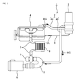
- a ventilation system 1 includes a breather pipe 2 and an oil separator unit 3.
- the breather pipe 2 partitions a returning channel for returning blow-by gas BG (oil-containing gas) discharged from a crankcase of an engine 4 to an air inlet side channel 5 that is in communication with the engine 4.
- the breather pipe 2 of the present embodiment returns the blow-by gas BG to a part of the air inlet side channel 5, at a position connecting an air filter 6 and a turbocharger 7.
- the oil separator unit 3 is provided halfway along the breather pipe 2, and separates and collects oil OL from the blow-by gas BG and returns the oil to the engine 4.
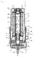
- the drain member 14 is a funnel-shaped member, and is connected to the lower end of the housing 11 from below. That is, the end surface on the wide opening side of the drain member 14 is joined to the lower end surface of the housing 11 in a liquid-tight manner.
- a unit accommodating space for accommodating the separation unit 16 is thereby partitioned by the housing 11 and the drain member 14.
- a narrowed portion (a squeezed channel) 14a of the drain member 14 is arranged facing downward, and functions as a discharge channel for discharging the separated oil OL.
- the oil OL which has been discharged from the narrowed portion 14a is returned to the engine 4 through the oil collection pipe 8, as shown in Figure 1 .
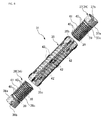
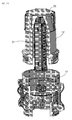
- the outer diameter of a lower end part 38a of the lower internal cylindrical member 38 is aligned with the inner diameter of the external cylindrical member 35, and the lower internal cylindrical member 38 is inserted into the inner space of the external cylindrical member 35 from the lower end side of the external cylindrical member 35.
- the lower end part 38a of the lower internal cylindrical member 38 is formed in the same manner as the upper end part 37a of the upper internal cylindrical member 37, and intimately contacts the inner circumferential surface of the external cylindrical member 35.
- a lower engaging claw 38b is provided in the lower end part 38a. The lower engaging claw 38b is used when attaching the lower internal cylindrical member 38 to the external cylindrical member 35.
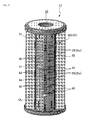
- the part above the lower end part 38a (referred to as a main part 38c for the sake of convenience) is formed in the same manner as the main part 37c of the upper internal cylindrical member 37, and injection holes 39 and strip protrusions 40 and 41 are formed thereto.
- a surface facing the injection holes 39 provided in the internal cylindrical member 34 is formed as a spraying surface 35a.
- the spraying surface 35a is a part where the blow-by gas BG injected from the injection holes 39 is sprayed. Since the spraying surface 35a of the present embodiment is the inner circumferential surface of the external cylindrical member 35, it is formed of a curved surface that is curved along the circumferential direction.
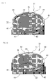
- the blow-by gas BG injected from the injection holes 39 after being injected onto the spraying surface 35a of the external cylindrical member 35 flows in the circumferential direction (the encircling direction) along the circumferential channel 43 at which the injection holes 39 is opened. Then, when it reaches the communication space 44, the blow-by gas BG changes the direction of flow and flows into the circumferential channel 43 at which the exhaust hole 42 is opened. That is, after being injected from the injection holes 39, the blow-by gas BG flows to the communication space 44 through the circumferential channel 43, makes a U-turn in the communication space 44, and flows through another circumferential channel 43 to be discharged from the exhaust hole 42.
- blow-by gas BG from which oil has been removed by the separation unit 16 flows into the inner space of the core 31.
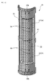
- This blow-by gas BG is purified by the core 31 and the filtering member 32 as shown in Figure 16(a) . That is, as shown in Figure 16(c) , oil mist OM, having carbon CB covered with oil as a core, is contained in the blow-by gas BG. Then, as shown in Figure 16(b) , when passing through the core 31, the blow-by gas BG is injected into the separation chamber 36 from the injection holes 39 provided in the internal cylindrical member 34.
- the oil mist contained in the blow-by gas BG is condensed on the spraying surface 35a, and is separated from the blow-by gas BG.
- the oil OL separated from the blow-by gas BG moves according to the flow of the blow-by gas BG, and moves through the circumferential channel 43 toward the communication space 44.
- the filter element 13 of the present embodiment is used in a standing position. That is, in the use state, one end of the core 31 in the axial direction is positioned lower than the other end.
- the oil OL which has reached the communication space 44 is prevented from moving in the circumferential direction by the axial strip protrusion 41 and flows down the communication space 44 due to its own weight.
- the oil OL which has flowed down the communication space 44 is stored in the lower end of the separation chamber 36.
- the amount of oil to be stored is not large.
- the oil OL is discharged to the outside (the filtering member 32) from the exhaust hole 42 provided at the lower end portion of the core 31.
- the exhaust hole 42 at the lowermost end functions also as an oil discharge portion.
- the circumferential channels 43 are partitioned off by the plurality of circumferential strip protrusions 40 provided on the outer circumferential surface of the internal cylindrical member 34 and the blow-by gas BG injected from the injection holes 39 is guided by the circumferential channels 43 along the circumferential direction, and thus, the separation of oil can be promoted by the centrifugal separation effect by rotation. Also, the blow-by gas BG is led to the exhaust hole 42 after making a U-turn in the communication space 44, and this also promotes the separation of oil.
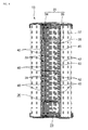
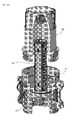
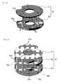
- the ceiling member 51 is a member that partitions a ceiling portion of the separation unit 16, and includes a ceiling plate 51a, an inner rib 51b and an outer rib 51c.
- the inner rib 51b is a protruding portion provided protruding downward (in the stacking direction of the members) from the edge of an opening provided in the ceiling plate 51a.
- This inner rib 51b is joined with an inner rib 52b of the first intermediate member 52.
- the outer rib 51c is a protruding portion provided protruding downward at the outer circumferential edge of the ceiling plate 51a.
- This outer rib 51c is joined with an outer rib 52c of the first intermediate member 52.
- the ceiling plate 51a and a first intermediate plate 52a of the first intermediate member 52 are supported with a predetermined gap therebetween by the inner ribs 51b and 52b, and the outer ribs 51c and 52c.
- the first intermediate member 52 is a member that is attached between the ceiling member 51 and the bottom member 54, and includes the first intermediate plate 52a, the inner rib 52b and the outer rib 52c.
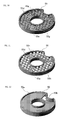
- the injection hole group of the first intermediate plate 52a is formed being shifted in the circumferential direction from the injection hole group of the ceiling plate 51a.
- the surface of the first intermediate plate 52a facing the injection hole group of the ceiling plate 51a thereby functions as a spraying surface onto which the blow-by gas BG is sprayed.
- the second intermediate member 53 is a member attached between the ceiling member 51 and the bottom member 54, and includes a second intermediate plate 53a, the inner rib 53b and the outer rib 53c.
- the position where the injection hole group of the second intermediate member 53 is formed is different from that of the injection hole group of the first intermediate plate 52a. That is, the injection hole group of the second intermediate plate 53a is provided at the same position as the injection hole group of the ceiling plate 51a in the circumferential direction.
- the surface of the second intermediate plate 53a facing the injection hole group of the first intermediate plate 52a thereby functions as a spraying surface onto which the blow-by gas BG is sprayed.
- other parts of the second intermediate member 53 are structured in the same manner as those of the first intermediate member 52, and an explanation thereof is omitted.
- the bottom member 54 is a member for partitioning the bottom portion of the separation unit 16, and includes a bottom plate 54a, an inner rib 54b and an outer rib 54c.
- the bottom plate 54a is a plate member having the same shape as the ceiling plate 51a, and a plurality of discharge holes 54d are formed thereto. These discharge holes 54d are parts for discharging, to the outside of the separation unit 16, the blow-by gas BG after separation of the oil OL (the separated gas) and the condensed oil OL, and functions both as a gas discharge portion and as an oil discharge portion. These discharge holes 54d are also formed radially from the center of the bottom plate 54a. That is, the discharge holes 54d are formed in a group of three with gaps therewith in the radial direction to form a discharge hole group, and the discharge hole groups are formed at 120 degrees angular intervals in the circumferential direction.
- the inner rib 54b is a protruding portion provided protruding upward from the edge of an opening provided in the bottom plate 54a.
- the inner rib 54b is joined with the inner rib 53b of the second intermediate member 53.
- the outer rib 54c is a protruding portion provided protruding upward from the outer circumferential edge of the bottom plate 54a.
- the outer rib 54c is joined with the outer rib 53c of the second intermediate member 53.
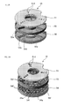
- a flat space curved in such a way as to circulate and guide the blow-by gas BG is formed between the ceiling plate 51a and the first intermediate plate 52a, between the first intermediate plate 52a and the second intermediate plate 53a, and between the second intermediate plate 53a and the bottom plate 54a.
- the flat space corresponds to a separation chamber for separating oil mist from the blow-by gas BG, and also, to a encircling channel curved in the encircling direction to guide the blow-by gas BG.
- the flat space of the present embodiment includes three spaces, the top, the middle and the bottom.
- the blow-by gas BG which has flowed into the top encircling channel TC1 is sprayed on the spraying surface of the first intermediate plate 52a.
- the oil mist contained in the blow-by gas BG is condensed on the surface of the first intermediate plate 52a and is separated from the blow-by gas BG.
- the oil OL separated from the blow-by gas BG is pushed by the blow-by gas BG and flows on the surface of the first intermediate plate 52a.
- the separated oil flows through the top encircling channel TC1 (the first encircling channel) in the right direction (the first encircling direction).
- blow-by gas BG is sprayed from the injection hole group of the ceiling plate 51a toward the spraying surface of the first intermediate plate 52a, and oil is separated from the blow-by gas BG by condensation. Oil is likewise separated from the blow-by gas BG by spraying the blow-by gas BG from the injection hole group of the first intermediate plate 52a toward the spraying surface of the second intermediate plate 53a, or spraying the blow-by gas BG from the injection hole group of the second intermediate plate 53a toward the spraying surface of the bottom plate 54a.
- the oil OL condensed on the spraying surface flows on the bottom surface of the encircling channel according to the flow of the blow-by gas BG, but by using the sloping member 56 of this modified example, the condensed oil OL moves by the downward slope of the bottom surface 56a and the flow of the blow-by gas BG. As a result, the condensed oil OL is less likely to remain in the encircling channel.
Landscapes
- Chemical & Material Sciences (AREA)
- Chemical Kinetics & Catalysis (AREA)
- Engineering & Computer Science (AREA)
- Mechanical Engineering (AREA)
- General Engineering & Computer Science (AREA)
- Physics & Mathematics (AREA)
- Geometry (AREA)
- Lubrication Details And Ventilation Of Internal Combustion Engines (AREA)
- Separating Particles In Gases By Inertia (AREA)
Applications Claiming Priority (1)
| Application Number | Priority Date | Filing Date | Title |
|---|---|---|---|
| PCT/JP2010/060756 WO2011161796A1 (ja) | 2010-06-24 | 2010-06-24 | ミスト状オイルの分離装置 |
Publications (3)
| Publication Number | Publication Date |
|---|---|
| EP2587009A1 true EP2587009A1 (de) | 2013-05-01 |
| EP2587009A4 EP2587009A4 (de) | 2013-12-11 |
| EP2587009B1 EP2587009B1 (de) | 2017-11-08 |
Family
ID=45371009
Family Applications (1)
| Application Number | Title | Priority Date | Filing Date |
|---|---|---|---|
| EP10853656.6A Not-in-force EP2587009B1 (de) | 2010-06-24 | 2010-06-24 | Ölnebelabscheider |
Country Status (5)
| Country | Link |
|---|---|
| US (1) | US9260992B2 (de) |
| EP (1) | EP2587009B1 (de) |
| JP (1) | JP5597709B2 (de) |
| CN (1) | CN103038467B (de) |
| WO (1) | WO2011161796A1 (de) |
Families Citing this family (19)
| Publication number | Priority date | Publication date | Assignee | Title |
|---|---|---|---|---|
| GB201113072D0 (en) * | 2011-07-29 | 2011-09-14 | Parker Hannifin Mfg Uk Ltd | A separator |
| US9034066B2 (en) * | 2011-09-16 | 2015-05-19 | Lawrence Livermore National Security, Llc | Anti-clogging filter system |
| JP5997513B2 (ja) * | 2012-06-28 | 2016-09-28 | 株式会社ニフコ | オイルセパレータ |
| US9144760B2 (en) * | 2012-07-03 | 2015-09-29 | The University Of Akron | Liquid drainage from coalescing filter medium with drainage channels |
| AT514708B1 (de) * | 2013-10-08 | 2015-03-15 | Ge Jenbacher Gmbh & Co Og | Filtervorrichtung |
| WO2016139716A1 (ja) * | 2015-03-02 | 2016-09-09 | 東京濾器株式会社 | 分離ディスク及びオイルセパレータ |
| US10913076B2 (en) * | 2015-03-02 | 2021-02-09 | Tokyo Roki Co., Ltd. | Oil separator |
| US9260993B1 (en) * | 2015-07-22 | 2016-02-16 | UPR Products, Inc. | Oil and air separator system and method |
| US10245539B2 (en) * | 2015-11-05 | 2019-04-02 | General Electric Company | Virtual impactor filter assembly and method |
| WO2017175323A1 (ja) * | 2016-04-06 | 2017-10-12 | 東京濾器株式会社 | オイルセパレータ |
| CN106015536B (zh) * | 2016-06-22 | 2018-06-01 | 山东交通职业学院 | 齿轮箱散热结构 |
| BE1025530B1 (nl) * | 2017-07-18 | 2019-04-05 | Atlas Copco Airpower Naamloze Vennootschap | Een filtersysteem voor het scheiden van vloeistof uit samengeperst gas en compressor omvattende een dergelijk filtersysteem |
| FR3071418B1 (fr) * | 2017-09-26 | 2019-09-13 | Safran Helicopter Engines | Piece pour degazeur centrifuge de turbomachine et procede de fabrication de ladite piece |
| WO2019079439A1 (en) * | 2017-10-19 | 2019-04-25 | K&N Engineering, Inc. | RATCHET OIL FILTER |
| JP2019108879A (ja) * | 2017-12-20 | 2019-07-04 | いすゞ自動車株式会社 | オイルセパレータ |
| JP6988439B2 (ja) * | 2017-12-20 | 2022-01-05 | いすゞ自動車株式会社 | オイルセパレータ |
| US11047274B2 (en) * | 2018-11-14 | 2021-06-29 | GM Global Technology Operations LLC | Air-oil separator |
| CN113623906B (zh) * | 2021-07-26 | 2024-11-22 | 珠海格力电器股份有限公司 | 油分离装置、冷凝器及空调系统 |
| CN117072443A (zh) * | 2023-08-16 | 2023-11-17 | 杭州久益机械股份有限公司 | 一种用于压缩机齿轮箱的油雾回收器及油雾回收方法 |
Family Cites Families (24)
| Publication number | Priority date | Publication date | Assignee | Title |
|---|---|---|---|---|
| US1496926A (en) * | 1921-09-19 | 1924-06-10 | Westing House Air Brake Compan | Oil separator |
| JPS4911094A (de) | 1972-05-25 | 1974-01-31 | ||
| DE2828256A1 (de) | 1978-06-28 | 1980-01-03 | Daimler Benz Ag | Vorrichtung zur entlueftung des kurbelwellengehaeuses einer brennkraftmaschine |
| US4387603A (en) * | 1979-06-25 | 1983-06-14 | Nelson Philip A | Bounceless high pressure drop cascade impactor and a method for determining particle size distribution of an aerosol |
| JPS5820652B2 (ja) * | 1981-04-17 | 1983-04-25 | 平山 利久 | 循環式集じん装置 |
| JPS61167422A (ja) * | 1985-01-22 | 1986-07-29 | Niigata Eng Co Ltd | ダスト捕集装置 |
| JPH02127723A (ja) | 1988-11-08 | 1990-05-16 | Hitachi Micro Comput Eng Ltd | データ端末装置 |
| JPH02127723U (de) * | 1989-03-30 | 1990-10-22 | ||
| US6290738B1 (en) * | 1999-07-16 | 2001-09-18 | Nelson Industries, Inc. | Inertial gas-liquid separator having an inertial collector spaced from a nozzle structure |
| JP2005279629A (ja) * | 2004-03-03 | 2005-10-13 | Union Sangyo Kk | オイルミストフィルタ及びオイルミストセパレータ |
| JP2005248926A (ja) * | 2004-03-08 | 2005-09-15 | Mitsubishi Fuso Truck & Bus Corp | ブローバイガス還流システムのベンチレータ装置 |
| US7828865B2 (en) * | 2008-07-31 | 2010-11-09 | Cummins Filtration Ip, Inc. | Gas-liquid separator with dual flow impaction and coalescence |
| US7473291B2 (en) | 2004-09-21 | 2009-01-06 | Cummins Filtration Ip, Inc. | Inertial gas-liquid separator with variable flow actuator |
| US7246612B2 (en) | 2004-10-08 | 2007-07-24 | Toyota Technical Center Usa, Inc | Oil separator |
| US7431748B2 (en) * | 2005-04-15 | 2008-10-07 | Enerco Group, Inc. | Separation device |
| DE102005042286A1 (de) | 2005-09-06 | 2007-04-12 | Mahle International Gmbh | Einrichtung zur Trennung eines Gas-Flüssigkeitsgemisches |
| ITTO20060333A1 (it) | 2006-05-09 | 2007-11-10 | Dayco Fuel Man Spa | Dispositivo separatore per un motore a combustibile interna di un autoveicolo |
| DE102006024816A1 (de) | 2006-05-29 | 2007-12-06 | Mahle International Gmbh | Einrichtung für die Entlüftung eines Kurbelgehäuses |
| DE102006024820A1 (de) * | 2006-05-29 | 2007-12-13 | Mahle International Gmbh | Einrichtung zur Trennung eines Gas-Flüssigkeitsgemisches, insbesondere bei der Entlüftung eines Kurbelgehäuses eines Verbrennungsmotors |
| US20080264018A1 (en) * | 2007-04-26 | 2008-10-30 | Herman Peter K | Inertial gas-liquid separator with slot nozzle |
| JP2008286075A (ja) * | 2007-05-16 | 2008-11-27 | Toyota Boshoku Corp | 気液分離装置 |
| FR2921101B1 (fr) | 2007-09-17 | 2014-09-05 | Renault Sas | Dispositif de filtrage des gaz de fuite d'un moteur a combustion interne |
| DE202007014378U1 (de) * | 2007-10-12 | 2009-02-26 | Hengst Gmbh & Co.Kg | Ölnebelabscheider einer Brennkraftmaschine |
| CN201280963Y (zh) * | 2008-10-07 | 2009-07-29 | 浙江方圆机电设备制造有限公司 | 一种油气分离器 |
-
2010
- 2010-06-24 US US13/806,619 patent/US9260992B2/en active Active
- 2010-06-24 CN CN201080067652.7A patent/CN103038467B/zh not_active Expired - Fee Related
- 2010-06-24 JP JP2012521229A patent/JP5597709B2/ja active Active
- 2010-06-24 EP EP10853656.6A patent/EP2587009B1/de not_active Not-in-force
- 2010-06-24 WO PCT/JP2010/060756 patent/WO2011161796A1/ja not_active Ceased
Also Published As
| Publication number | Publication date |
|---|---|
| CN103038467B (zh) | 2015-10-07 |
| CN103038467A (zh) | 2013-04-10 |
| JPWO2011161796A1 (ja) | 2013-08-19 |
| US20130205726A1 (en) | 2013-08-15 |
| WO2011161796A1 (ja) | 2011-12-29 |
| EP2587009B1 (de) | 2017-11-08 |
| JP5597709B2 (ja) | 2014-10-01 |
| EP2587009A4 (de) | 2013-12-11 |
| US9260992B2 (en) | 2016-02-16 |
Similar Documents
| Publication | Publication Date | Title |
|---|---|---|
| EP2587009B1 (de) | Ölnebelabscheider | |
| JP6286117B2 (ja) | オイル分離方法 | |
| JP5847445B2 (ja) | 内燃機関のオイルセパレータ | |
| US20160177791A1 (en) | Oil mist separator | |
| US20090229585A1 (en) | Oil separator for blow-by gas | |
| WO2015111345A1 (ja) | ブローバイガス用オイルセパレータ | |
| JP2014105582A (ja) | オイルセパレータ | |
| WO2012157309A1 (ja) | 内燃機関のオイルセパレータ | |
| JP4690257B2 (ja) | オイルミストセパレータ | |
| US10946320B2 (en) | Oil separating device | |
| US10968796B2 (en) | Breather structure of engine | |
| JP6126885B2 (ja) | オイルミストの分離装置 | |
| JP2018531340A6 (ja) | オイル分離装置 | |
| WO2015178310A1 (ja) | オイルセパレータ | |
| JP2015217367A5 (de) | ||
| JP2010144696A (ja) | フィルタ式気液分離装置 | |
| CN111256398B (zh) | 油分离器及具有其的制冷系统 | |
| JP5495402B2 (ja) | オイルセパレータ | |
| US20190178122A1 (en) | Oil Separators | |
| JP6660426B2 (ja) | エンジンのブリーザ構造 | |
| JP6721639B2 (ja) | エンジンのブリーザ構造 | |
| JP2007332873A (ja) | ブローバイガスのトラップ装置 | |
| JPH0441210Y2 (de) | ||
| HK1209678B (en) | Oil separator | |
| JP2018091286A (ja) | シリンダヘッドカバーおよびそれを備えたエンジン |
Legal Events
| Date | Code | Title | Description |
|---|---|---|---|
| PUAI | Public reference made under article 153(3) epc to a published international application that has entered the european phase |
Free format text: ORIGINAL CODE: 0009012 |
|
| 17P | Request for examination filed |
Effective date: 20130108 |
|
| AK | Designated contracting states |
Kind code of ref document: A1 Designated state(s): AL AT BE BG CH CY CZ DE DK EE ES FI FR GB GR HR HU IE IS IT LI LT LU LV MC MK MT NL NO PL PT RO SE SI SK SM TR |
|
| DAX | Request for extension of the european patent (deleted) | ||
| A4 | Supplementary search report drawn up and despatched |
Effective date: 20131113 |
|
| RIC1 | Information provided on ipc code assigned before grant |
Ipc: F01M 13/04 20060101AFI20131107BHEP |
|
| 17Q | First examination report despatched |
Effective date: 20140825 |
|
| STAA | Information on the status of an ep patent application or granted ep patent |
Free format text: STATUS: EXAMINATION IS IN PROGRESS |
|
| GRAP | Despatch of communication of intention to grant a patent |
Free format text: ORIGINAL CODE: EPIDOSNIGR1 |
|
| STAA | Information on the status of an ep patent application or granted ep patent |
Free format text: STATUS: GRANT OF PATENT IS INTENDED |
|
| INTG | Intention to grant announced |
Effective date: 20170522 |
|
| GRAS | Grant fee paid |
Free format text: ORIGINAL CODE: EPIDOSNIGR3 |
|
| GRAA | (expected) grant |
Free format text: ORIGINAL CODE: 0009210 |
|
| STAA | Information on the status of an ep patent application or granted ep patent |
Free format text: STATUS: THE PATENT HAS BEEN GRANTED |
|
| AK | Designated contracting states |
Kind code of ref document: B1 Designated state(s): AL AT BE BG CH CY CZ DE DK EE ES FI FR GB GR HR HU IE IS IT LI LT LU LV MC MK MT NL NO PL PT RO SE SI SK SM TR |
|
| REG | Reference to a national code |
Ref country code: GB Ref legal event code: FG4D |
|
| REG | Reference to a national code |
Ref country code: CH Ref legal event code: EP Ref country code: AT Ref legal event code: REF Ref document number: 944364 Country of ref document: AT Kind code of ref document: T Effective date: 20171115 |
|
| REG | Reference to a national code |
Ref country code: IE Ref legal event code: FG4D |
|
| REG | Reference to a national code |
Ref country code: DE Ref legal event code: R096 Ref document number: 602010046635 Country of ref document: DE |
|
| REG | Reference to a national code |
Ref country code: NL Ref legal event code: MP Effective date: 20171108 |
|
| REG | Reference to a national code |
Ref country code: LT Ref legal event code: MG4D |
|
| REG | Reference to a national code |
Ref country code: AT Ref legal event code: MK05 Ref document number: 944364 Country of ref document: AT Kind code of ref document: T Effective date: 20171108 |
|
| PG25 | Lapsed in a contracting state [announced via postgrant information from national office to epo] |
Ref country code: LT Free format text: LAPSE BECAUSE OF FAILURE TO SUBMIT A TRANSLATION OF THE DESCRIPTION OR TO PAY THE FEE WITHIN THE PRESCRIBED TIME-LIMIT Effective date: 20171108 Ref country code: NO Free format text: LAPSE BECAUSE OF FAILURE TO SUBMIT A TRANSLATION OF THE DESCRIPTION OR TO PAY THE FEE WITHIN THE PRESCRIBED TIME-LIMIT Effective date: 20180208 Ref country code: NL Free format text: LAPSE BECAUSE OF FAILURE TO SUBMIT A TRANSLATION OF THE DESCRIPTION OR TO PAY THE FEE WITHIN THE PRESCRIBED TIME-LIMIT Effective date: 20171108 Ref country code: FI Free format text: LAPSE BECAUSE OF FAILURE TO SUBMIT A TRANSLATION OF THE DESCRIPTION OR TO PAY THE FEE WITHIN THE PRESCRIBED TIME-LIMIT Effective date: 20171108 Ref country code: SE Free format text: LAPSE BECAUSE OF FAILURE TO SUBMIT A TRANSLATION OF THE DESCRIPTION OR TO PAY THE FEE WITHIN THE PRESCRIBED TIME-LIMIT Effective date: 20171108 Ref country code: ES Free format text: LAPSE BECAUSE OF FAILURE TO SUBMIT A TRANSLATION OF THE DESCRIPTION OR TO PAY THE FEE WITHIN THE PRESCRIBED TIME-LIMIT Effective date: 20171108 |
|
| PG25 | Lapsed in a contracting state [announced via postgrant information from national office to epo] |
Ref country code: HR Free format text: LAPSE BECAUSE OF FAILURE TO SUBMIT A TRANSLATION OF THE DESCRIPTION OR TO PAY THE FEE WITHIN THE PRESCRIBED TIME-LIMIT Effective date: 20171108 Ref country code: GR Free format text: LAPSE BECAUSE OF FAILURE TO SUBMIT A TRANSLATION OF THE DESCRIPTION OR TO PAY THE FEE WITHIN THE PRESCRIBED TIME-LIMIT Effective date: 20180209 Ref country code: BG Free format text: LAPSE BECAUSE OF FAILURE TO SUBMIT A TRANSLATION OF THE DESCRIPTION OR TO PAY THE FEE WITHIN THE PRESCRIBED TIME-LIMIT Effective date: 20180208 Ref country code: LV Free format text: LAPSE BECAUSE OF FAILURE TO SUBMIT A TRANSLATION OF THE DESCRIPTION OR TO PAY THE FEE WITHIN THE PRESCRIBED TIME-LIMIT Effective date: 20171108 Ref country code: IS Free format text: LAPSE BECAUSE OF FAILURE TO SUBMIT A TRANSLATION OF THE DESCRIPTION OR TO PAY THE FEE WITHIN THE PRESCRIBED TIME-LIMIT Effective date: 20180308 Ref country code: AT Free format text: LAPSE BECAUSE OF FAILURE TO SUBMIT A TRANSLATION OF THE DESCRIPTION OR TO PAY THE FEE WITHIN THE PRESCRIBED TIME-LIMIT Effective date: 20171108 |
|
| PG25 | Lapsed in a contracting state [announced via postgrant information from national office to epo] |
Ref country code: CZ Free format text: LAPSE BECAUSE OF FAILURE TO SUBMIT A TRANSLATION OF THE DESCRIPTION OR TO PAY THE FEE WITHIN THE PRESCRIBED TIME-LIMIT Effective date: 20171108 Ref country code: CY Free format text: LAPSE BECAUSE OF FAILURE TO SUBMIT A TRANSLATION OF THE DESCRIPTION OR TO PAY THE FEE WITHIN THE PRESCRIBED TIME-LIMIT Effective date: 20171108 Ref country code: EE Free format text: LAPSE BECAUSE OF FAILURE TO SUBMIT A TRANSLATION OF THE DESCRIPTION OR TO PAY THE FEE WITHIN THE PRESCRIBED TIME-LIMIT Effective date: 20171108 Ref country code: SK Free format text: LAPSE BECAUSE OF FAILURE TO SUBMIT A TRANSLATION OF THE DESCRIPTION OR TO PAY THE FEE WITHIN THE PRESCRIBED TIME-LIMIT Effective date: 20171108 Ref country code: DK Free format text: LAPSE BECAUSE OF FAILURE TO SUBMIT A TRANSLATION OF THE DESCRIPTION OR TO PAY THE FEE WITHIN THE PRESCRIBED TIME-LIMIT Effective date: 20171108 |
|
| REG | Reference to a national code |
Ref country code: DE Ref legal event code: R097 Ref document number: 602010046635 Country of ref document: DE |
|
| PG25 | Lapsed in a contracting state [announced via postgrant information from national office to epo] |
Ref country code: IT Free format text: LAPSE BECAUSE OF FAILURE TO SUBMIT A TRANSLATION OF THE DESCRIPTION OR TO PAY THE FEE WITHIN THE PRESCRIBED TIME-LIMIT Effective date: 20171108 Ref country code: RO Free format text: LAPSE BECAUSE OF FAILURE TO SUBMIT A TRANSLATION OF THE DESCRIPTION OR TO PAY THE FEE WITHIN THE PRESCRIBED TIME-LIMIT Effective date: 20171108 Ref country code: PL Free format text: LAPSE BECAUSE OF FAILURE TO SUBMIT A TRANSLATION OF THE DESCRIPTION OR TO PAY THE FEE WITHIN THE PRESCRIBED TIME-LIMIT Effective date: 20171108 Ref country code: SM Free format text: LAPSE BECAUSE OF FAILURE TO SUBMIT A TRANSLATION OF THE DESCRIPTION OR TO PAY THE FEE WITHIN THE PRESCRIBED TIME-LIMIT Effective date: 20171108 |
|
| PLBE | No opposition filed within time limit |
Free format text: ORIGINAL CODE: 0009261 |
|
| STAA | Information on the status of an ep patent application or granted ep patent |
Free format text: STATUS: NO OPPOSITION FILED WITHIN TIME LIMIT |
|
| 26N | No opposition filed |
Effective date: 20180809 |
|
| PG25 | Lapsed in a contracting state [announced via postgrant information from national office to epo] |
Ref country code: SI Free format text: LAPSE BECAUSE OF FAILURE TO SUBMIT A TRANSLATION OF THE DESCRIPTION OR TO PAY THE FEE WITHIN THE PRESCRIBED TIME-LIMIT Effective date: 20171108 |
|
| REG | Reference to a national code |
Ref country code: CH Ref legal event code: PL |
|
| GBPC | Gb: european patent ceased through non-payment of renewal fee |
Effective date: 20180624 |
|
| REG | Reference to a national code |
Ref country code: BE Ref legal event code: MM Effective date: 20180630 |
|
| REG | Reference to a national code |
Ref country code: IE Ref legal event code: MM4A |
|
| PG25 | Lapsed in a contracting state [announced via postgrant information from national office to epo] |
Ref country code: LU Free format text: LAPSE BECAUSE OF NON-PAYMENT OF DUE FEES Effective date: 20180624 Ref country code: MC Free format text: LAPSE BECAUSE OF FAILURE TO SUBMIT A TRANSLATION OF THE DESCRIPTION OR TO PAY THE FEE WITHIN THE PRESCRIBED TIME-LIMIT Effective date: 20171108 |
|
| PG25 | Lapsed in a contracting state [announced via postgrant information from national office to epo] |
Ref country code: FR Free format text: LAPSE BECAUSE OF NON-PAYMENT OF DUE FEES Effective date: 20180630 Ref country code: LI Free format text: LAPSE BECAUSE OF NON-PAYMENT OF DUE FEES Effective date: 20180630 Ref country code: CH Free format text: LAPSE BECAUSE OF NON-PAYMENT OF DUE FEES Effective date: 20180630 Ref country code: IE Free format text: LAPSE BECAUSE OF NON-PAYMENT OF DUE FEES Effective date: 20180624 Ref country code: GB Free format text: LAPSE BECAUSE OF NON-PAYMENT OF DUE FEES Effective date: 20180624 |
|
| PG25 | Lapsed in a contracting state [announced via postgrant information from national office to epo] |
Ref country code: BE Free format text: LAPSE BECAUSE OF NON-PAYMENT OF DUE FEES Effective date: 20180630 |
|
| PGFP | Annual fee paid to national office [announced via postgrant information from national office to epo] |
Ref country code: DE Payment date: 20190612 Year of fee payment: 10 |
|
| PG25 | Lapsed in a contracting state [announced via postgrant information from national office to epo] |
Ref country code: MT Free format text: LAPSE BECAUSE OF NON-PAYMENT OF DUE FEES Effective date: 20180624 |
|
| PG25 | Lapsed in a contracting state [announced via postgrant information from national office to epo] |
Ref country code: TR Free format text: LAPSE BECAUSE OF FAILURE TO SUBMIT A TRANSLATION OF THE DESCRIPTION OR TO PAY THE FEE WITHIN THE PRESCRIBED TIME-LIMIT Effective date: 20171108 |
|
| PG25 | Lapsed in a contracting state [announced via postgrant information from national office to epo] |
Ref country code: PT Free format text: LAPSE BECAUSE OF FAILURE TO SUBMIT A TRANSLATION OF THE DESCRIPTION OR TO PAY THE FEE WITHIN THE PRESCRIBED TIME-LIMIT Effective date: 20171108 Ref country code: HU Free format text: LAPSE BECAUSE OF FAILURE TO SUBMIT A TRANSLATION OF THE DESCRIPTION OR TO PAY THE FEE WITHIN THE PRESCRIBED TIME-LIMIT; INVALID AB INITIO Effective date: 20100624 |
|
| PG25 | Lapsed in a contracting state [announced via postgrant information from national office to epo] |
Ref country code: MK Free format text: LAPSE BECAUSE OF NON-PAYMENT OF DUE FEES Effective date: 20171108 |
|
| PG25 | Lapsed in a contracting state [announced via postgrant information from national office to epo] |
Ref country code: AL Free format text: LAPSE BECAUSE OF FAILURE TO SUBMIT A TRANSLATION OF THE DESCRIPTION OR TO PAY THE FEE WITHIN THE PRESCRIBED TIME-LIMIT Effective date: 20171108 |
|
| REG | Reference to a national code |
Ref country code: DE Ref legal event code: R119 Ref document number: 602010046635 Country of ref document: DE |
|
| PG25 | Lapsed in a contracting state [announced via postgrant information from national office to epo] |
Ref country code: DE Free format text: LAPSE BECAUSE OF NON-PAYMENT OF DUE FEES Effective date: 20210101 |