EP2596989A2 - Dispositif et procédé de détermination de variables pour adapter la répartition de lumière d'un phare droit et d'un phare gauche dans les virages - Google Patents
Dispositif et procédé de détermination de variables pour adapter la répartition de lumière d'un phare droit et d'un phare gauche dans les virages Download PDFInfo
- Publication number
- EP2596989A2 EP2596989A2 EP12193515.9A EP12193515A EP2596989A2 EP 2596989 A2 EP2596989 A2 EP 2596989A2 EP 12193515 A EP12193515 A EP 12193515A EP 2596989 A2 EP2596989 A2 EP 2596989A2
- Authority
- EP
- European Patent Office
- Prior art keywords
- angle
- information
- headlamp
- vehicle
- limited
- Prior art date
- Legal status (The legal status is an assumption and is not a legal conclusion. Google has not performed a legal analysis and makes no representation as to the accuracy of the status listed.)
- Granted
Links
Images


Classifications
-
- B—PERFORMING OPERATIONS; TRANSPORTING
- B60—VEHICLES IN GENERAL
- B60Q—ARRANGEMENT OF SIGNALLING OR LIGHTING DEVICES, THE MOUNTING OR SUPPORTING THEREOF OR CIRCUITS THEREFOR, FOR VEHICLES IN GENERAL
- B60Q1/00—Arrangement of optical signalling or lighting devices, the mounting or supporting thereof or circuits therefor
- B60Q1/02—Arrangement of optical signalling or lighting devices, the mounting or supporting thereof or circuits therefor the devices being primarily intended to illuminate the way ahead or to illuminate other areas of way or environments
- B60Q1/04—Arrangement of optical signalling or lighting devices, the mounting or supporting thereof or circuits therefor the devices being primarily intended to illuminate the way ahead or to illuminate other areas of way or environments the devices being headlights
- B60Q1/06—Arrangement of optical signalling or lighting devices, the mounting or supporting thereof or circuits therefor the devices being primarily intended to illuminate the way ahead or to illuminate other areas of way or environments the devices being headlights adjustable, e.g. remotely-controlled from inside vehicle
- B60Q1/08—Arrangement of optical signalling or lighting devices, the mounting or supporting thereof or circuits therefor the devices being primarily intended to illuminate the way ahead or to illuminate other areas of way or environments the devices being headlights adjustable, e.g. remotely-controlled from inside vehicle automatically
- B60Q1/12—Arrangement of optical signalling or lighting devices, the mounting or supporting thereof or circuits therefor the devices being primarily intended to illuminate the way ahead or to illuminate other areas of way or environments the devices being headlights adjustable, e.g. remotely-controlled from inside vehicle automatically due to steering position
- B60Q1/122—Arrangement of optical signalling or lighting devices, the mounting or supporting thereof or circuits therefor the devices being primarily intended to illuminate the way ahead or to illuminate other areas of way or environments the devices being headlights adjustable, e.g. remotely-controlled from inside vehicle automatically due to steering position with electrical actuating means
-
- B—PERFORMING OPERATIONS; TRANSPORTING
- B60—VEHICLES IN GENERAL
- B60Q—ARRANGEMENT OF SIGNALLING OR LIGHTING DEVICES, THE MOUNTING OR SUPPORTING THEREOF OR CIRCUITS THEREFOR, FOR VEHICLES IN GENERAL
- B60Q2300/00—Indexing codes for automatically adjustable headlamps or automatically dimmable headlamps
- B60Q2300/10—Indexing codes relating to particular vehicle conditions
- B60Q2300/11—Linear movements of the vehicle
- B60Q2300/112—Vehicle speed
-
- B—PERFORMING OPERATIONS; TRANSPORTING
- B60—VEHICLES IN GENERAL
- B60Q—ARRANGEMENT OF SIGNALLING OR LIGHTING DEVICES, THE MOUNTING OR SUPPORTING THEREOF OR CIRCUITS THEREFOR, FOR VEHICLES IN GENERAL
- B60Q2300/00—Indexing codes for automatically adjustable headlamps or automatically dimmable headlamps
- B60Q2300/10—Indexing codes relating to particular vehicle conditions
- B60Q2300/12—Steering parameters
- B60Q2300/122—Steering angle
-
- B—PERFORMING OPERATIONS; TRANSPORTING
- B60—VEHICLES IN GENERAL
- B60Q—ARRANGEMENT OF SIGNALLING OR LIGHTING DEVICES, THE MOUNTING OR SUPPORTING THEREOF OR CIRCUITS THEREFOR, FOR VEHICLES IN GENERAL
- B60Q2300/00—Indexing codes for automatically adjustable headlamps or automatically dimmable headlamps
- B60Q2300/10—Indexing codes relating to particular vehicle conditions
- B60Q2300/13—Attitude of the vehicle body
- B60Q2300/134—Yaw
-
- B—PERFORMING OPERATIONS; TRANSPORTING
- B60—VEHICLES IN GENERAL
- B60Q—ARRANGEMENT OF SIGNALLING OR LIGHTING DEVICES, THE MOUNTING OR SUPPORTING THEREOF OR CIRCUITS THEREFOR, FOR VEHICLES IN GENERAL
- B60Q2300/00—Indexing codes for automatically adjustable headlamps or automatically dimmable headlamps
- B60Q2300/30—Indexing codes relating to the vehicle environment
- B60Q2300/32—Road surface or travel path
- B60Q2300/322—Road curvature
Definitions
- first information such as speed, yaw rate and steering wheel angle
- vehicle information used for controlling the pivoting of a light cone of a right headlamp and a left headlamp of a vehicle based on the first information such as speed, yaw rate and steering wheel angle
- the predictive cornering light eliminates the problems of the dynamic cornering light, which can arise, for example, when cornering or cornering, since the headlights of the predictive cornering light always the predictive tilt angle is set.
- a further disadvantage of methods known today is that, unlike dynamic cornering light, the driver can no longer exert any influence on the direction of pivoting of the headlights when there is predictive pivoting. In practice, this may mean that the predictively tilted headlight often reaches its maximum possible pivoting angle before the driver enters a bend. That in the moment when the driver moves the steering wheel, there is no reaction in the photograph, since the headlamps have already reached their maximum possible pivoting angle through the predictive pivoting. This is unusual for the driver and could reduce the acceptance of the system.
- devices are known with which both a dynamic and a predictive tilt angle can be adjusted.
- a device is for example from the document DE 10 2005 036 948 A1 known.
- second information such as curvature and / or turning radius and / or turning direction are used together with first information, for example the current speed and / or the current steering wheel angle, to determine predictive and dynamic swivel angles.
- static and / or distance-dependent and / or speed-dependent start and end points of curves are needed as control aids for the activation / deactivation or transitions between the setting of the dynamic and the predictive swivel angle.
- the document DE 10 2005 036 948 shows, among other things, several ways in which different predictive and dynamic swivel angles can be selected for the headlights.
- the predictive tilt angle is initially set indefinitely. Achieved the dynamic tilt angle z. B. after a defined time not the predictive tilt angle, the predictive tilt angle is successively reduced to the dynamic tilt angle, ie limited. The thus successively limited predictive swivel angle is given as a reference variable to the headlights.
- the present invention is based on the problem of improving the predictive adjustment of the light distribution of the headlights of a motor vehicle so that on the one hand errors of the prediction can not have an unlimited effect and on the other hand the driver can influence the adaptation of the light distribution in particular driving situations.
- the adjustment of the light distribution can be done on the one hand by the pivoting of a headlamp or a part of a headlamp.
- light-emitting diodes may also be provided in headlamps, which are interconnected to form a so-called light-emitting diode array.
- the light distribution of the light emitted by such headlights can be changed.
- a pan does not take place then.
- the invention extends to both headlamps with conventional bulbs and headlamps with LED arrays. In relation to the invention is therefore not focused on the pivoting of headlights or parts of a headlamp. Nor is there any talk in terms of the invention of a pivoting direction or a sweep angle, as these terms may be misleading with respect to headlamps with light emitting diode arrays.
- the problem underlying the invention is achieved according to the invention in that by means of the control means the second angle p can be limited to a limited second angle p L if an amount
- a deviation a pd between the second angle p and the first angle d is greater than a maximum permissible deviation a max .
- angles, swivel movements correspond to the definitions in DIN ISO 4130. Accordingly, angles to the left of the vehicle longitudinal axis are indicated with negative signs and angles to the right of the vehicle longitudinal axis with positive signs.
- the limitation of the second angle p always takes place when there is a more than permissible deviation a max of the determined second angle p from the first angle. Large deviations are often present when the second angle has been incorrectly determined because the second information was totally or partially wrong. The error of the determination can then have no unlimited effect in the invention and it remains ensured that the limited second angle used to determine the reference variable remains in connection with the actual driving situation.
- the driver can gain a greater influence on the adaptation of the light distribution since, for example as a result of strong steering movements, as a result of evasive maneuvers, he will increase the deviation of the second angle from the first angle and thus have a resounding influence of the first angle first angle up can reach the set on the headlights angle, as will be explained below.
- the first and the second angle are intermediate variables or variables which initially serve only as calculation purposes within the control means. Only in conventional headlamps, the first angle and the second angle on the headlamps adjustable angle to the vehicle longitudinal axis, which are also commonly referred to as a dynamic swivel angle or predictive swivel angle. The first angle and the second angle also need not be provided with units in the calculation within the control means. The designation of the first angle and the second angle as an angle was chosen only because of the proximity to the dynamic feed angle or predictive tilt angle. Likewise one could from a first value or a second value o.ä. speak.
- the limited second angle p L may correspond to the first angle d plus the maximum allowable deviation a max when the second angle p is greater than the first angle d. If, however, the second angle p is smaller than the first angle d, the limited second angle p L advantageously corresponds to the first angle d minus the maximum permissible deviation a max . In both cases, the first angle d has a disruptive effect on the limited second angle.
- the maximum permissible deviation can be a constant value. It is also possible that the maximum permissible deviation a max is dependent on first information and / or second information. This makes it possible to adapt the maximum permissible deviation to the driving situation and to the predicted course of the road.
- the second angle p can be selected for the right and the left headlamp, or, in the case of a limitation of the second angle p, the limited second angle p L , which is used to determine the reference variables. Is it in the invention for determining reference variables for adaptation the light distribution of conventional headlamps, the predictive tilt angle p and the limited predictive tilt angle p L is then set on both headlamps.
- the first angle d can be selected for the right-hand headlamp and the second angle p L for the left-hand headlamp, or the limited second angle p L in the case of a limitation of the second angle p if the second angle p is smaller than the first angle d.
- the limited second angle p L be selected when the second angle p greater is the first angle d. It is therefore also possible that the first angle is set on one of the two headlights and the second or limited second angle is set on the other of the two headlights. This can lead to a wider illumination of the vehicle apron, especially when cornering.
- the control means of a device may be suitable and adapted to switch between the selection of the first angle d for one of the headlights and the selection of the second angle p or limited second angle p L for the same headlight when the first angle d is equal to the second angle p.
- Vehicle F represented as a block has a right-hand headlamp S R and a left-hand headlamp S L. Both headlights preferably have motors as actuators with which the headlights can be pivoted horizontally to pivot the beam direction of the headlights horizontally. These are conventional headlights, not headlights with LED arrays. It is thus possible to pivot the headlights S R , S L in such a way that it illuminates in the direction of the road ahead of the vehicle. The vehicle is therefore equipped with so-called cornering light.
- the dynamic cornering light takes into account for determining the pivoting direction of the headlights information that take into account the current state of the vehicle, which is described by first information that can be provided by sensors S and / or ECUs in the vehicle. What this first information can include has already been explained in the introduction.
- a swivel angle determined on the basis of the first information is referred to as the first angle. Since this angle is actually set on the headlamps of the embodiment, the first angle is hereinafter referred to as the dynamic pivot angle d.
- the predictive cornering light takes into account information that takes into account the road ahead, in particular the road course.
- This second information can be provided, for example, by a navigation system and / or by a camera system K. What this second information can include has also been previously introduced.
- a determined based on the second information Swing angle is referred to as the second angle. Since this angle is actually set on the headlamps of the embodiment, the second angle is hereinafter referred to as predictive swing angle p.
- the device F for controlling the pivoting of a right headlamp S R and a left headlamp S L of a vehicle F is provided in the vehicle F.
- the device V comprises an interface I, via which the device V is connected to the camera system K and various control devices EC and sensors S.
- the first information or the second information provided by the control devices EC and / or sensors S or by the camera system can be read into the device V via the interface I.
- a control means C which processes the first information and the second information and determines the dynamic swivel angle d from the first information and the predictive swivel angle p from the second information. With the control means C is also selected whether the dynamic swivel angle d or the predictive swivel angle p to the right and the left headlight S R , S L should be set.
- the apparatus further comprises a means for converting said selected by the control means C for the right headlamp S R swivel angle d, p and selected by the control means C for the left headlamp S L Schenk angle d, p provided in the command signals.
- the command variable signals can be transmitted via a further interface I to the actuators of the headlights S R , S L.
- the actuators process the reference variable signals for pivoting the headlights or for shifting the gusset, for example, in LED systems in accordance with the selected pivoting angles d, p.
- the selection of the swivel angle takes place, for example, after in the Fig. 2 or in the Fig. 3 illustrated method.
- the predictive swivel angle p is smaller than the dynamic swivel angle. If this is the case, in a step 2 for the right-hand headlamp S R, the dynamic swivel angle is selected as the swivel angle to be set. If this is not the case, the dynamic swivel angle is selected in step 3 for the left-hand headlamp S L.
- step 4 it is checked in step 4 whether the amount
- the deviation a pd of the predictive swivel angle p from the dynamic swivel angle d is less than or equal to a maximum permissible deviation a max . If this is the case, in step 5 for the left-hand headlamp the predictive swivel angle is selected as the swivel angle to be set. If this is not the case, a limited predictive pivot angle p L is determined and selected in step 6 for the left-hand headlamp, which is equal to the difference da max from the dynamic swivel angle d and the maximum permissible deviation a max .
- step 7 it is checked whether the amount
- the deviation a pd of the predictive swivel angle p from the dynamic swivel angle d is less than or equal to a maximum permissible deviation a max . If this is the case, in step 8 for the right-hand headlamp, the predictive swivel angle is selected as the swivel angle to be set. If this is not the case, a limited predictive pivot angle p L is determined and selected in step 9 for the right-hand headlamp, which is equal to the sum d + a max from the dynamic swivel angle d and the maximum permissible deviation a max .
- the dynamic swivel angle is always selected for a headlamp SR, SL, while for the other headlamp S L , S R either the predictive swivel angle p or the limited predictive swivel angle p L is selected.
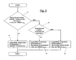
- step 11 After the start of the in Fig. 3 in a step 11, it is first checked whether the amount
- the deviation a pd of the predictive swivel angle p from the dynamic swivel angle d is less than or equal to a maximum permissible deviation a max . If this is the case, in step 12 for the right-hand headlamp S R and the left-hand headlamp S L, the predictive swivel angle p is selected as the swivel angle to be set. If this is not the case, it is checked in step 13 whether the predictive swivel angle p is greater than the dynamic swivel angle.
- a limited predictive pivot angle p L is determined and selected in a step 14 for the right-hand headlamp S R and the left-hand headlamp S L , which is equal to the sum d + a max from the dynamic swivel angle d and the maximum permissible deviation a max is. If, after examination in step 13, the predictive swivel angle p is less than or equal to the dynamic swivel angle d, a limited predictive swivel angle p L is determined and selected in step 15 for the right-hand headlamp S R and the left-hand headlamp S L equal to the difference da max from the dynamic swing angle d and the maximum allowable deviation a max .
Landscapes
- Engineering & Computer Science (AREA)
- Mechanical Engineering (AREA)
- Lighting Device Outwards From Vehicle And Optical Signal (AREA)
Applications Claiming Priority (1)
| Application Number | Priority Date | Filing Date | Title |
|---|---|---|---|
| DE102011055597A DE102011055597B3 (de) | 2011-11-22 | 2011-11-22 | Vorrichtung und Verfahren zur Ermittelung von Führungsgrößen zur Anpassung der Lichtverteilung eines rechten Scheinwerfers und eines linken Scheinwerfers bei Kurvenfahrten |
Publications (3)
| Publication Number | Publication Date |
|---|---|
| EP2596989A2 true EP2596989A2 (fr) | 2013-05-29 |
| EP2596989A3 EP2596989A3 (fr) | 2014-02-05 |
| EP2596989B1 EP2596989B1 (fr) | 2018-03-07 |
Family
ID=47227634
Family Applications (1)
| Application Number | Title | Priority Date | Filing Date |
|---|---|---|---|
| EP12193515.9A Not-in-force EP2596989B1 (fr) | 2011-11-22 | 2012-11-21 | Dispositif et procédé de détermination de variables pour adapter la répartition de lumière d'un phare droit et d'un phare gauche dans les virages |
Country Status (4)
| Country | Link |
|---|---|
| US (1) | US9333902B2 (fr) |
| EP (1) | EP2596989B1 (fr) |
| CN (1) | CN103129448B (fr) |
| DE (1) | DE102011055597B3 (fr) |
Families Citing this family (7)
| Publication number | Priority date | Publication date | Assignee | Title |
|---|---|---|---|---|
| DE102013108342A1 (de) * | 2013-08-02 | 2015-02-05 | Hella Kgaa Hueck & Co. | Verfahren für die Erzeugung eines Ausleuchtbereichs vor einem Fahrzeug |
| DE102014205864A1 (de) | 2014-03-28 | 2015-10-01 | Automotive Lighting Reutlingen Gmbh | Verfahren zur Realisierung eines Verschwenkens eines Lichtschwerpunkts einer Lichtverteilung einer Beleuchtungseinrichtung eines Kraftfahrzeugs und Beleuchtungseinrichtung eines Kraftfahrzeugs zur Realisierung eines solchen Verfahrens |
| DE102016122492A1 (de) * | 2016-11-22 | 2018-05-24 | HELLA GmbH & Co. KGaA | Erzeugung einer homogenen Lichtverteilung in Abhängigkeit von der Topografie und der gemessenen Leuchtdichte |
| KR102202125B1 (ko) * | 2017-06-02 | 2021-01-13 | 현대모비스 주식회사 | 조향 정보를 이용한 배광 제어 장치 및 방법 |
| CN108032798B (zh) * | 2017-12-13 | 2023-06-20 | 辽宁工业大学 | 一种高速公路超车时自动工作的转向灯装置及控制方法 |
| CN112406694A (zh) * | 2020-11-16 | 2021-02-26 | 东风汽车集团有限公司 | 一种汽车转向灯自动控制系统及方法 |
| DE102022105234A1 (de) * | 2022-03-07 | 2023-09-07 | HELLA GmbH & Co. KGaA | Scheinwerfer für Fahrzeuge |
Citations (1)
| Publication number | Priority date | Publication date | Assignee | Title |
|---|---|---|---|---|
| DE102005036948A1 (de) | 2004-08-06 | 2006-07-27 | Denso Corp., Kariya | Fahrzeugscheinwerfergerät |
Family Cites Families (14)
| Publication number | Priority date | Publication date | Assignee | Title |
|---|---|---|---|---|
| JPH07110595B2 (ja) * | 1987-10-13 | 1995-11-29 | 本田技研工業株式会社 | 二輪車のヘッドライト装置 |
| JP3111153B2 (ja) * | 1995-01-17 | 2000-11-20 | 本田技研工業株式会社 | 車両用前照灯装置 |
| JP3622808B2 (ja) * | 1996-06-03 | 2005-02-23 | 本田技研工業株式会社 | 車両用前照灯装置 |
| JPH10203232A (ja) * | 1997-01-29 | 1998-08-04 | Honda Motor Co Ltd | 車両用前照灯装置 |
| JP2002104065A (ja) * | 2000-09-28 | 2002-04-09 | Denso Corp | 車両用前照灯光軸方向自動調整装置 |
| US7239627B2 (en) * | 2001-05-24 | 2007-07-03 | Adc Dsl Systems, Inc. | Digital subscriber line services |
| JP4593034B2 (ja) * | 2001-08-31 | 2010-12-08 | 株式会社デンソー | 車両用前照灯光軸方向自動調整装置 |
| DE10221902B4 (de) * | 2002-05-16 | 2012-09-13 | Volkswagen Ag | Verfahren zum Steuern des horizontalen Schwenkwinkels eines Fahrzeugscheinwerfers |
| JP4199064B2 (ja) * | 2003-07-10 | 2008-12-17 | 株式会社小糸製作所 | 車両用照明装置 |
| US7477976B2 (en) * | 2003-07-28 | 2009-01-13 | Denso Corporation | Automatic optical axis direction adjusting apparatus for vehicles |
| EP1757486B1 (fr) * | 2005-08-26 | 2014-04-30 | Nissan Motor Co., Ltd. | Dispositif et procédé de contrôle pour projecteurs de véhicules |
| JP4710740B2 (ja) * | 2006-07-04 | 2011-06-29 | 株式会社デンソー | 位置情報利用装置 |
| JP2008110685A (ja) * | 2006-10-31 | 2008-05-15 | Denso Corp | 前照灯スイブル制御装置 |
| JP4349410B2 (ja) * | 2006-12-01 | 2009-10-21 | トヨタ自動車株式会社 | 車両用照明装置 |
-
2011
- 2011-11-22 DE DE102011055597A patent/DE102011055597B3/de not_active Expired - Fee Related
-
2012
- 2012-11-20 US US13/682,467 patent/US9333902B2/en active Active
- 2012-11-21 EP EP12193515.9A patent/EP2596989B1/fr not_active Not-in-force
- 2012-11-22 CN CN201210477788.6A patent/CN103129448B/zh not_active Expired - Fee Related
Patent Citations (1)
| Publication number | Priority date | Publication date | Assignee | Title |
|---|---|---|---|---|
| DE102005036948A1 (de) | 2004-08-06 | 2006-07-27 | Denso Corp., Kariya | Fahrzeugscheinwerfergerät |
Also Published As
| Publication number | Publication date |
|---|---|
| US20130201705A1 (en) | 2013-08-08 |
| CN103129448B (zh) | 2017-05-24 |
| US9333902B2 (en) | 2016-05-10 |
| EP2596989A3 (fr) | 2014-02-05 |
| DE102011055597B3 (de) | 2013-02-28 |
| CN103129448A (zh) | 2013-06-05 |
| EP2596989B1 (fr) | 2018-03-07 |
Similar Documents
| Publication | Publication Date | Title |
|---|---|---|
| EP2596989B1 (fr) | Dispositif et procédé de détermination de variables pour adapter la répartition de lumière d'un phare droit et d'un phare gauche dans les virages | |
| DE102008057313B4 (de) | Verfahren und Vorrichtung zur Bestimmung eines korrigierenden Lenkmoments | |
| EP3554907B1 (fr) | Procédé de régulation automatique de la vitesse d'une motocyclette | |
| EP2156983B1 (fr) | Procédé et dispositif de commande de la ligne de coupure verticale de phares | |
| EP2094521B1 (fr) | Système d'assistance au conducteur et procédé d'assistance au conducteur pour le maintien de la voie | |
| EP2156984B1 (fr) | Procédé et dispositif de commande de ligne de coupure verticale de phares | |
| DE102009044269A1 (de) | Lenkassistentenvorrichtung | |
| EP1594714A1 (fr) | Procede pour regler la vitesse de deplacement d'un vehicule | |
| DE10210723A1 (de) | Spurwechselassistent für Kraftfahrzeuge | |
| DE102010039399A1 (de) | Prädiktiv-adaptive Frontbeleuchtung eines Kraftfahrzeuges | |
| DE102014209771A1 (de) | Verfahren zur Steuerung eines Kurvenlichts und Beleuchtungsvorrichtung | |
| WO2015120874A1 (fr) | Procédé d'utilisation d'un système de véhicule conçu pour la conduite au moins partiellement automatique d'un véhicule et véhicule automobile | |
| EP2384932B1 (fr) | Procédé de commande prédictive d'un phare de virage adaptatif et véhicule automobile | |
| WO2018103875A1 (fr) | Procédé de commande de distribution d'une lumière avant d'un véhicule | |
| DE102021202343A1 (de) | Straßenverlaufsberücksichtigung beim Betreiben eines Steer-by-Wire-Lenksystems | |
| EP4192720A1 (fr) | Procédé de fonctionnement d'un système de direction à commande électrique d'un véhicule motorisé, dispositif de commande, programme informatique, et système de direction à commande électrique | |
| DE102008054207A1 (de) | Verfahren und Vorrichtung zur Führung eines Fahrzeugs entlang einer vorgebbaren Solltrajektorie | |
| EP2298603B1 (fr) | Procédé de commande prédictive d'un phare de virage adaptatif et véhicule automobile | |
| DE60305089T2 (de) | Automatisches Lenkregelsystem und -verfahren | |
| EP3213981B1 (fr) | Méthode de parcage automatique d'un véhicule dans un emplacement selon un profil de vitesse pré-établi, système d'assistance et véhicule | |
| DE102009035634B4 (de) | Verfahren zur Unterstützung eines Fahrers eines Kraftfahrzeugs während eines Schleudervorgangs und entsprechendes Kraftfahrzeug | |
| EP2119593A1 (fr) | Appareil de commande et/ou de contrôle d'une ligne de coupure verticale de phares d'un véhicule | |
| WO2015135668A1 (fr) | Procédé et dispositif servant à faire fonctionner un véhicule | |
| EP2957461B1 (fr) | Vehicule automobile et procede de preparation d'un feu de croisement statique | |
| EP3088248A1 (fr) | Procede destine au fonctionnement d'un dispositif d'eclairage d'un vehicule automobile et dispositif d'eclairage pour un vehicule automobile |
Legal Events
| Date | Code | Title | Description |
|---|---|---|---|
| PUAI | Public reference made under article 153(3) epc to a published international application that has entered the european phase |
Free format text: ORIGINAL CODE: 0009012 |
|
| AK | Designated contracting states |
Kind code of ref document: A2 Designated state(s): AL AT BE BG CH CY CZ DE DK EE ES FI FR GB GR HR HU IE IS IT LI LT LU LV MC MK MT NL NO PL PT RO RS SE SI SK SM TR |
|
| AX | Request for extension of the european patent |
Extension state: BA ME |
|
| PUAL | Search report despatched |
Free format text: ORIGINAL CODE: 0009013 |
|
| AK | Designated contracting states |
Kind code of ref document: A3 Designated state(s): AL AT BE BG CH CY CZ DE DK EE ES FI FR GB GR HR HU IE IS IT LI LT LU LV MC MK MT NL NO PL PT RO RS SE SI SK SM TR |
|
| AX | Request for extension of the european patent |
Extension state: BA ME |
|
| RIC1 | Information provided on ipc code assigned before grant |
Ipc: B60Q 1/12 20060101AFI20140102BHEP |
|
| 17P | Request for examination filed |
Effective date: 20140331 |
|
| RBV | Designated contracting states (corrected) |
Designated state(s): AL AT BE BG CH CY CZ DE DK EE ES FI FR GB GR HR HU IE IS IT LI LT LU LV MC MK MT NL NO PL PT RO RS SE SI SK SM TR |
|
| GRAP | Despatch of communication of intention to grant a patent |
Free format text: ORIGINAL CODE: EPIDOSNIGR1 |
|
| INTG | Intention to grant announced |
Effective date: 20171114 |
|
| RAP1 | Party data changed (applicant data changed or rights of an application transferred) |
Owner name: HELLA GMBH & CO. KGAA |
|
| GRAS | Grant fee paid |
Free format text: ORIGINAL CODE: EPIDOSNIGR3 |
|
| GRAA | (expected) grant |
Free format text: ORIGINAL CODE: 0009210 |
|
| AK | Designated contracting states |
Kind code of ref document: B1 Designated state(s): AL AT BE BG CH CY CZ DE DK EE ES FI FR GB GR HR HU IE IS IT LI LT LU LV MC MK MT NL NO PL PT RO RS SE SI SK SM TR |
|
| REG | Reference to a national code |
Ref country code: GB Ref legal event code: FG4D Free format text: NOT ENGLISH |
|
| REG | Reference to a national code |
Ref country code: CH Ref legal event code: EP Ref country code: AT Ref legal event code: REF Ref document number: 976189 Country of ref document: AT Kind code of ref document: T Effective date: 20180315 |
|
| REG | Reference to a national code |
Ref country code: IE Ref legal event code: FG4D Free format text: LANGUAGE OF EP DOCUMENT: GERMAN |
|
| REG | Reference to a national code |
Ref country code: DE Ref legal event code: R096 Ref document number: 502012012288 Country of ref document: DE |
|
| REG | Reference to a national code |
Ref country code: NL Ref legal event code: MP Effective date: 20180307 |
|
| REG | Reference to a national code |
Ref country code: LT Ref legal event code: MG4D |
|
| PG25 | Lapsed in a contracting state [announced via postgrant information from national office to epo] |
Ref country code: FI Free format text: LAPSE BECAUSE OF FAILURE TO SUBMIT A TRANSLATION OF THE DESCRIPTION OR TO PAY THE FEE WITHIN THE PRESCRIBED TIME-LIMIT Effective date: 20180307 Ref country code: CY Free format text: LAPSE BECAUSE OF FAILURE TO SUBMIT A TRANSLATION OF THE DESCRIPTION OR TO PAY THE FEE WITHIN THE PRESCRIBED TIME-LIMIT Effective date: 20180307 Ref country code: ES Free format text: LAPSE BECAUSE OF FAILURE TO SUBMIT A TRANSLATION OF THE DESCRIPTION OR TO PAY THE FEE WITHIN THE PRESCRIBED TIME-LIMIT Effective date: 20180307 Ref country code: LT Free format text: LAPSE BECAUSE OF FAILURE TO SUBMIT A TRANSLATION OF THE DESCRIPTION OR TO PAY THE FEE WITHIN THE PRESCRIBED TIME-LIMIT Effective date: 20180307 Ref country code: NO Free format text: LAPSE BECAUSE OF FAILURE TO SUBMIT A TRANSLATION OF THE DESCRIPTION OR TO PAY THE FEE WITHIN THE PRESCRIBED TIME-LIMIT Effective date: 20180607 Ref country code: HR Free format text: LAPSE BECAUSE OF FAILURE TO SUBMIT A TRANSLATION OF THE DESCRIPTION OR TO PAY THE FEE WITHIN THE PRESCRIBED TIME-LIMIT Effective date: 20180307 |
|
| PG25 | Lapsed in a contracting state [announced via postgrant information from national office to epo] |
Ref country code: GR Free format text: LAPSE BECAUSE OF FAILURE TO SUBMIT A TRANSLATION OF THE DESCRIPTION OR TO PAY THE FEE WITHIN THE PRESCRIBED TIME-LIMIT Effective date: 20180608 Ref country code: BG Free format text: LAPSE BECAUSE OF FAILURE TO SUBMIT A TRANSLATION OF THE DESCRIPTION OR TO PAY THE FEE WITHIN THE PRESCRIBED TIME-LIMIT Effective date: 20180607 Ref country code: RS Free format text: LAPSE BECAUSE OF FAILURE TO SUBMIT A TRANSLATION OF THE DESCRIPTION OR TO PAY THE FEE WITHIN THE PRESCRIBED TIME-LIMIT Effective date: 20180307 Ref country code: LV Free format text: LAPSE BECAUSE OF FAILURE TO SUBMIT A TRANSLATION OF THE DESCRIPTION OR TO PAY THE FEE WITHIN THE PRESCRIBED TIME-LIMIT Effective date: 20180307 Ref country code: SE Free format text: LAPSE BECAUSE OF FAILURE TO SUBMIT A TRANSLATION OF THE DESCRIPTION OR TO PAY THE FEE WITHIN THE PRESCRIBED TIME-LIMIT Effective date: 20180307 |
|
| PG25 | Lapsed in a contracting state [announced via postgrant information from national office to epo] |
Ref country code: MT Free format text: LAPSE BECAUSE OF FAILURE TO SUBMIT A TRANSLATION OF THE DESCRIPTION OR TO PAY THE FEE WITHIN THE PRESCRIBED TIME-LIMIT Effective date: 20180307 |
|
| REG | Reference to a national code |
Ref country code: FR Ref legal event code: PLFP Year of fee payment: 7 |
|
| PG25 | Lapsed in a contracting state [announced via postgrant information from national office to epo] |
Ref country code: PL Free format text: LAPSE BECAUSE OF FAILURE TO SUBMIT A TRANSLATION OF THE DESCRIPTION OR TO PAY THE FEE WITHIN THE PRESCRIBED TIME-LIMIT Effective date: 20180307 Ref country code: EE Free format text: LAPSE BECAUSE OF FAILURE TO SUBMIT A TRANSLATION OF THE DESCRIPTION OR TO PAY THE FEE WITHIN THE PRESCRIBED TIME-LIMIT Effective date: 20180307 Ref country code: NL Free format text: LAPSE BECAUSE OF FAILURE TO SUBMIT A TRANSLATION OF THE DESCRIPTION OR TO PAY THE FEE WITHIN THE PRESCRIBED TIME-LIMIT Effective date: 20180307 Ref country code: RO Free format text: LAPSE BECAUSE OF FAILURE TO SUBMIT A TRANSLATION OF THE DESCRIPTION OR TO PAY THE FEE WITHIN THE PRESCRIBED TIME-LIMIT Effective date: 20180307 Ref country code: IT Free format text: LAPSE BECAUSE OF FAILURE TO SUBMIT A TRANSLATION OF THE DESCRIPTION OR TO PAY THE FEE WITHIN THE PRESCRIBED TIME-LIMIT Effective date: 20180307 Ref country code: AL Free format text: LAPSE BECAUSE OF FAILURE TO SUBMIT A TRANSLATION OF THE DESCRIPTION OR TO PAY THE FEE WITHIN THE PRESCRIBED TIME-LIMIT Effective date: 20180307 |
|
| PG25 | Lapsed in a contracting state [announced via postgrant information from national office to epo] |
Ref country code: SK Free format text: LAPSE BECAUSE OF FAILURE TO SUBMIT A TRANSLATION OF THE DESCRIPTION OR TO PAY THE FEE WITHIN THE PRESCRIBED TIME-LIMIT Effective date: 20180307 Ref country code: SM Free format text: LAPSE BECAUSE OF FAILURE TO SUBMIT A TRANSLATION OF THE DESCRIPTION OR TO PAY THE FEE WITHIN THE PRESCRIBED TIME-LIMIT Effective date: 20180307 Ref country code: CZ Free format text: LAPSE BECAUSE OF FAILURE TO SUBMIT A TRANSLATION OF THE DESCRIPTION OR TO PAY THE FEE WITHIN THE PRESCRIBED TIME-LIMIT Effective date: 20180307 |
|
| REG | Reference to a national code |
Ref country code: DE Ref legal event code: R097 Ref document number: 502012012288 Country of ref document: DE |
|
| PG25 | Lapsed in a contracting state [announced via postgrant information from national office to epo] |
Ref country code: PT Free format text: LAPSE BECAUSE OF FAILURE TO SUBMIT A TRANSLATION OF THE DESCRIPTION OR TO PAY THE FEE WITHIN THE PRESCRIBED TIME-LIMIT Effective date: 20180709 |
|
| PLBE | No opposition filed within time limit |
Free format text: ORIGINAL CODE: 0009261 |
|
| STAA | Information on the status of an ep patent application or granted ep patent |
Free format text: STATUS: NO OPPOSITION FILED WITHIN TIME LIMIT |
|
| PG25 | Lapsed in a contracting state [announced via postgrant information from national office to epo] |
Ref country code: DK Free format text: LAPSE BECAUSE OF FAILURE TO SUBMIT A TRANSLATION OF THE DESCRIPTION OR TO PAY THE FEE WITHIN THE PRESCRIBED TIME-LIMIT Effective date: 20180307 |
|
| 26N | No opposition filed |
Effective date: 20181210 |
|
| PG25 | Lapsed in a contracting state [announced via postgrant information from national office to epo] |
Ref country code: SI Free format text: LAPSE BECAUSE OF FAILURE TO SUBMIT A TRANSLATION OF THE DESCRIPTION OR TO PAY THE FEE WITHIN THE PRESCRIBED TIME-LIMIT Effective date: 20180307 |
|
| REG | Reference to a national code |
Ref country code: CH Ref legal event code: PL |
|
| GBPC | Gb: european patent ceased through non-payment of renewal fee |
Effective date: 20181121 |
|
| PG25 | Lapsed in a contracting state [announced via postgrant information from national office to epo] |
Ref country code: MC Free format text: LAPSE BECAUSE OF FAILURE TO SUBMIT A TRANSLATION OF THE DESCRIPTION OR TO PAY THE FEE WITHIN THE PRESCRIBED TIME-LIMIT Effective date: 20180307 Ref country code: LU Free format text: LAPSE BECAUSE OF NON-PAYMENT OF DUE FEES Effective date: 20181121 |
|
| REG | Reference to a national code |
Ref country code: BE Ref legal event code: MM Effective date: 20181130 |
|
| REG | Reference to a national code |
Ref country code: IE Ref legal event code: MM4A |
|
| PG25 | Lapsed in a contracting state [announced via postgrant information from national office to epo] |
Ref country code: LI Free format text: LAPSE BECAUSE OF NON-PAYMENT OF DUE FEES Effective date: 20181130 Ref country code: CH Free format text: LAPSE BECAUSE OF NON-PAYMENT OF DUE FEES Effective date: 20181130 |
|
| PG25 | Lapsed in a contracting state [announced via postgrant information from national office to epo] |
Ref country code: IE Free format text: LAPSE BECAUSE OF NON-PAYMENT OF DUE FEES Effective date: 20181121 |
|
| PG25 | Lapsed in a contracting state [announced via postgrant information from national office to epo] |
Ref country code: BE Free format text: LAPSE BECAUSE OF NON-PAYMENT OF DUE FEES Effective date: 20181130 |
|
| PG25 | Lapsed in a contracting state [announced via postgrant information from national office to epo] |
Ref country code: GB Free format text: LAPSE BECAUSE OF NON-PAYMENT OF DUE FEES Effective date: 20181121 |
|
| PGFP | Annual fee paid to national office [announced via postgrant information from national office to epo] |
Ref country code: FR Payment date: 20191014 Year of fee payment: 8 |
|
| PG25 | Lapsed in a contracting state [announced via postgrant information from national office to epo] |
Ref country code: TR Free format text: LAPSE BECAUSE OF FAILURE TO SUBMIT A TRANSLATION OF THE DESCRIPTION OR TO PAY THE FEE WITHIN THE PRESCRIBED TIME-LIMIT Effective date: 20180307 |
|
| PGFP | Annual fee paid to national office [announced via postgrant information from national office to epo] |
Ref country code: AT Payment date: 20191025 Year of fee payment: 8 |
|
| PG25 | Lapsed in a contracting state [announced via postgrant information from national office to epo] |
Ref country code: MK Free format text: LAPSE BECAUSE OF NON-PAYMENT OF DUE FEES Effective date: 20180307 Ref country code: HU Free format text: LAPSE BECAUSE OF FAILURE TO SUBMIT A TRANSLATION OF THE DESCRIPTION OR TO PAY THE FEE WITHIN THE PRESCRIBED TIME-LIMIT; INVALID AB INITIO Effective date: 20121121 |
|
| PG25 | Lapsed in a contracting state [announced via postgrant information from national office to epo] |
Ref country code: IS Free format text: LAPSE BECAUSE OF FAILURE TO SUBMIT A TRANSLATION OF THE DESCRIPTION OR TO PAY THE FEE WITHIN THE PRESCRIBED TIME-LIMIT Effective date: 20180707 |
|
| REG | Reference to a national code |
Ref country code: AT Ref legal event code: MM01 Ref document number: 976189 Country of ref document: AT Kind code of ref document: T Effective date: 20201121 |
|
| PG25 | Lapsed in a contracting state [announced via postgrant information from national office to epo] |
Ref country code: AT Free format text: LAPSE BECAUSE OF NON-PAYMENT OF DUE FEES Effective date: 20201121 |
|
| PG25 | Lapsed in a contracting state [announced via postgrant information from national office to epo] |
Ref country code: FR Free format text: LAPSE BECAUSE OF NON-PAYMENT OF DUE FEES Effective date: 20201130 |
|
| PGFP | Annual fee paid to national office [announced via postgrant information from national office to epo] |
Ref country code: DE Payment date: 20230926 Year of fee payment: 12 |
|
| REG | Reference to a national code |
Ref country code: DE Ref legal event code: R119 Ref document number: 502012012288 Country of ref document: DE |
|
| PG25 | Lapsed in a contracting state [announced via postgrant information from national office to epo] |
Ref country code: DE Free format text: LAPSE BECAUSE OF NON-PAYMENT OF DUE FEES Effective date: 20250603 |