EP2602412A2 - Agencement de ferrure - Google Patents
Agencement de ferrure Download PDFInfo
- Publication number
- EP2602412A2 EP2602412A2 EP12179343.4A EP12179343A EP2602412A2 EP 2602412 A2 EP2602412 A2 EP 2602412A2 EP 12179343 A EP12179343 A EP 12179343A EP 2602412 A2 EP2602412 A2 EP 2602412A2
- Authority
- EP
- European Patent Office
- Prior art keywords
- locking bar
- extension rail
- fitting arrangement
- rail
- locking
- Prior art date
- Legal status (The legal status is an assumption and is not a legal conclusion. Google has not performed a legal analysis and makes no representation as to the accuracy of the status listed.)
- Granted
Links
Images


Classifications
-
- E—FIXED CONSTRUCTIONS
- E05—LOCKS; KEYS; WINDOW OR DOOR FITTINGS; SAFES
- E05C—BOLTS OR FASTENING DEVICES FOR WINGS, SPECIALLY FOR DOORS OR WINDOWS
- E05C9/00—Arrangements of simultaneously actuated bolts or other securing devices at well-separated positions on the same wing
- E05C9/20—Coupling means for sliding bars, rods, or cables
-
- E—FIXED CONSTRUCTIONS
- E05—LOCKS; KEYS; WINDOW OR DOOR FITTINGS; SAFES
- E05C—BOLTS OR FASTENING DEVICES FOR WINGS, SPECIALLY FOR DOORS OR WINDOWS
- E05C9/00—Arrangements of simultaneously actuated bolts or other securing devices at well-separated positions on the same wing
- E05C9/004—Faceplates ; Fixing the faceplates to the wing
-
- E—FIXED CONSTRUCTIONS
- E05—LOCKS; KEYS; WINDOW OR DOOR FITTINGS; SAFES
- E05C—BOLTS OR FASTENING DEVICES FOR WINGS, SPECIALLY FOR DOORS OR WINDOWS
- E05C9/00—Arrangements of simultaneously actuated bolts or other securing devices at well-separated positions on the same wing
- E05C9/006—Details of bars
Definitions
- the present invention relates to a fitting arrangement for windows, doors or the like with a frame and with a wing for receiving the fitting arrangement.
- Wings of windows, doors and the like are in various dimensions on the market and are also custom-made in many cases to meet the requirements in each case.
- a suitable fitting arrangement must be provided for each wing size.
- fitting arrangements have been developed, the configuration of which on site can be individually adapted to the prevailing conditions. For example, a drive rod of the fitting assembly is made with oversize and then cut in a suitable manner, but this is associated with some labor and in particular with a significant loss of material.
- Telescopic fittings which can be pulled apart telescopically or pushed together to adapt to the respective present wing size. Although such fittings can be used flexibly in many areas, however, the maximum length change achievable by the telescopic pulling apart and pushing together of the corresponding components is usually relatively limited. In addition, problems may arise when a handle for actuating the Fitting arrangement is arranged asymmetrically on the wing, so that one end of the wing is not reached even in a maximum extended state of the telescopic fitting and / or a minimum length of the telescopic fitting is too large and consequently also in a "retracted" state over one end of the Out of the wing.
- the fitting arrangement should also be reliably operable, be simple and robust and be inexpensive to manufacture.
- the fitting arrangement Starting from a telescopically adaptable fitting arrangement with a gear rod and a locking bar, which are displaceable or decoupled relative to each other for mounting the fitting assembly on the wing and which are drive-effectively coupled together in an assembled state, wherein the locking bar at its end facing away from the gear rod a functional portion which comprises at least one functional element for coupling to a further component of the fitting arrangement or to the frame, the fitting arrangement according to the invention additionally has an extension rail.
- the extension rail is provided with a functional portion which is formed at least in functional terms as the functional portion of the locking bar. To extend the locking bar this can be coupled with the extension rail.
- extension rail which can be coupled to it so that its "reach" can be increased.
- the extension rail can be provided in different lengths, so that together with the "reach” or telescopic length of the telescopic mechanism of the telescopic fitting a wide range of wing sizes can be covered.
- the difference from one extension rail length to the next is determined by the telescopic length of the telescopic mechanism of the conventional telescopic fitting.
- the functional portion of the extension rail is formed at least in functional terms as the functional portion of the locking bar. That The other fitting components can be easily coupled to the extension rail without any structural changes are required. Also, the functional components of the frame do not need to be adjusted.
- the fitting arrangement comprises a coupling element for actuating a central closure of the wing, which is compatible with the extension rail and the locking bar and coupled.
- the fitting arrangement may have a free end portion of the extension rail and / or the locking bar at least partially covering the end cover which can be coupled with a faceplate, which covers a center of the associated drive rod at least partially.
- the end cover may have an opening through which in a mounted state formed on the extension rail bar exclusion or trained on the locking rod bar exclusion protrudes, the bar exclusion of the extension rail and the bar exclusion of the locking bar are functionally equivalent acting, in particular substantially the same.
- the extension rail and the locking bar in an assembled state of the extension rail at least partially overlapping arranged to facilitate a reliable assembly of the two components mentioned.
- the extension rail and / or the locking bar may be formed cranked in the overlapping region, for example, to ensure that the extension rail and the locking bar extend substantially in a common plane.
- the extension rail on a cranked portion which is suitable for receiving the locking bar and / or vice versa.
- both components in the overlapping region are bent in order to achieve the desired relative spatial arrangement of the extension rail and the locking bar.
- the extension rail can be secured in a mounted state by means of a securing means on the locking bar.
- the securing means is in particular a cover rail, wherein the locking bar is arranged at least in sections between the extension rail and the cover rail.
- This "sandwich" design ensures a reliable coupling of the locking bar and the extension rail and is structurally simple.
- the cover rail is doing a double function. On the one hand, it serves as a securing means, on the other hand, it ultimately acts at least in sections as a faceplate.
- the extension rail may have a pin which protrudes through an opening of the locking bar in an assembled state of the extension rail.
- the pin can be secured on the side facing away from the extension rail of the locking bar by a securing means - for example, the above-mentioned cover rail - against movement from the opening.
- a securing means for example, the above-mentioned cover rail - against movement from the opening.
- the pin is mushroom-shaped and protrudes in an assembled state of the securing means through an opening of the securing means, wherein the securing means engages behind a mushroom head of the pin.
- the opening of the securing means may for example be a slot with widened insertion.
- the end cover and / or the covering rail can be fastened to the wing; in particular, fastening elements for fastening the end cover and / or the covering rail project in an assembled state of the fitting arrangement through openings provided on the extension rail and / or the locking bar.
- the openings can be elongated holes.
- the extension rail and the locking bar may be provided with a locking pin for locking the wing, wherein a distance of the locking pin of the extension rail from its end facing away from the locking bar corresponds to a corresponding distance of the locking pin of the locking bar from its end facing the extension rail to a compatibility of the fitting assembly also to ensure in an extended state of the locking bar.
- the coupling mechanism is designed such that it can be brought for a mounting of the fitting assembly on the wing of a release position in a coupling position, wherein the gear rod and the locking bar in the release position substantially free, in particular continuously against each other are movable. In the coupling position, the gear rod and the locking bar are drivingly connected to each other.
- the coupling mechanism may also be configured to define discrete relative positioning of the gear bar and latch bar.
- Both a freely or continuously adjustable design of the coupling mechanism and a coupling mechanism with discrete positioning function may have at least one toothing formed on the gear rod and at least one toothing formed on the locking rod, which are coupled directly or indirectly to each other.
- a so-called tooth box can be used, which is arranged on the gear or locking bar. It has e.g. a substantially U-shaped cross-section, wherein on inner longitudinal sides of the tooth box toothings are arranged, which can be coupled with complementary formed counter teeth, which are associated with the bolt or the gear rod. By the teeth and the counter teeth discrete coupling states of the bolt and the gear rod are defined.
- At least one toothing is respectively arranged on the gear rod and the locking bar and is coupled to one another via at least one toothed wheel. If you fix a rotation axis of the gear, then the two rods are firmly coupled together. If you let the gear rotate freely, the rods can be moved relative to each other.
- the coupling mechanism with spatially fixed or displaceable Gear that allows a substantially stepless relative positioning of the two rods.
- the latter has at least one toothing formed on the gear rod or at least one toothing formed on the locking rod, which toothing cooperates with a latching mechanism provided on the locking rod or the gear rod.
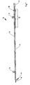
- Fig. 1 shows a partially disassembled fitting assembly 10 with a locking bar 12, which is in turn in a mounted state with a gear rod (not shown) drivingly coupled.
- the locking bar 12 is displaceable relative to the gear rod or completely decoupled from this.
- the longitudinal extension of the fitting assembly 10 by a relative displacement of the locking bar 12 and the gear rod to the respective present Dimensions of a wing of a window, a door or the like are adapted to which the fitting assembly 10 is to be mounted.
- Various types of coupling of the locking bar 12 and the gear rod are conceivable and have already been briefly described by way of example, so that no longer needs to be addressed at this point.
- the fitting assembly 10 has a longitudinal extent that is variably adjustable by a coupling mechanism coupling the locking bar 12 and the gear rod.
- an extension rail 14 is provided which can be coupled to the locking bar 12.
- one of the locking bar 12 opposite end of the extension rail 14 is formed substantially as a front of the connection with the extension rail 14 free end of the locking bar 12.
- Both the locking bar 12 and the extension rail 14 have a locking pin 16 which is provided for locking the fitting assembly 10 associated wing on the corresponding frame.
- the locking bar 12 and the extension rail 14 are each provided with a bar exclusion 18, slots 20, 20 'and holes 22, 22'.
- the components described above are designed and arranged to have the same effect, at least in functional terms, so that the end of the extension rail 14 provided with said components at least functionally simulates the free end of the locking bar 12. This in turn has the consequence that with the mentioned components cooperating components of the fitting assembly 10 and or the frame need not be changed when the extension rail 14 is used.
- the extension rail 14 also has a slot 20 ", which is aligned in an assembled state of the rail 14 with the slot 20 of the locking bar 12.
- Fig. 1 also shows a cuff rail section 24 and an end cover 26 which are used in mounting the extension rail 14 to the latch bar 12, as will be described below with reference to FIGS FIGS. 2 to 5 is explained.
- a pin 28 of the extension rail 14 is inserted into the hole 22 of the locking bar 12, whereby the rod 12 and the rail 14 are coupled together.
- the extension rail 14 is movable in substantially the same plane as the originally free end of the locking bar 12 - which is desirable for reasons of comfort - the extension rail 14 is formed cranked in the portion facing the locking bar 12. The same applies vice versa for the locking bar 12th
- the originally free end of the locking bar 12 is arranged in the cranked region of the extension rail 14 - and vice versa - what in Fig. 2 you can see.
- the locking bar 12 and the extension rail 14 thereby overlap in an overlapping area 30.
- the faceplate section 24 is mounted.
- the cuff rail section 24 has elongated holes 32, 32 ', which are assigned to the locking pin 16 of the locking bar 12 or the pin 28. While the slot 32 ensures that the locking pin 16 relative to the Stulpschienenabterrorism 24, which adjoins the covering of the moving parts of the fitting assembly 10 substantially directly to a Stulpschienenabterrorism 24 'of the locking bar 12, remains displaceable, the slot 32' is provided to the connection between the locking bar 12 and the extension rail fourteenth to secure. For this purpose, the pin 28 is inserted into an insertion hole 34 of the slot 32 '. Subsequently, the faceplate section 24 is displaced in the longitudinal direction.
- the cuff rail portion 24 engages behind a mushroom-shaped head of the pin 28, whereby the cuff rail portion 24 and the extension rail 14 are secured against lifting and thus securely coupled together. Ultimately, therefore, the free end of the locking bar 12 at the beginning of assembly between the Stulpschienenabêt 24 and the cranked portion of the extension rail 14 is fixed, as in Fig. 3 is shown.
- the end cover 26 On the free end of the extension rail 14, the end cover 26 is then attached (see also 4 and 5 ), which serves to cover the free end of the extension rail 14 and thus also has a covering function similar to a faceplate.
- a provided on the end cover 26 and the locking pin 16 associated slot 32 "corresponds functionally to the slot 32 of the cuff rail section 24th
- the end cover 26 is provided with an opening 38 which allows the passage of the bar exclusion 18. Furthermore, the end cover 26 has a coupling portion 40 which is hook-shaped and thereby allows coupling with a faceplate, which in turn at least partially covers a mechanism of a center closure. This coupling function facilitates the installation of the center lock associated components and increases the stability of the fitting assembly 10 in total.
- the end cover 26 can also be easily attached to the locking bar 12, if the extension rail 14 is not needed.
- Fig. 5 shows a preassembled state of the fitting assembly 10. This is then secured by means of mounting holes 42 of the components 26, 24, 24 'guided mounting screws (not shown) on the wing. Through the slots 20, 20 ', 20 "ensures that the locking bar 12 and the extension rail 14, despite the fastening screws relative to the components 26, 24, 24' remain displaceable.
- Fig. 6 shows a section of the fitting assembly 10 in a side view to illustrate the mushroom-shaped configuration of the head of the pin 28. As previously described, it serves together with the cuff rail portion 24 to secure the coupling between the latch bar 12 and the extension rail 14. If a cover of the rod 12 and the rail 14 is not essential, the cuff rail portion 24 may also be configured so that he essentially serves only as a backup. It can then be made much shorter, since he ultimately only the slot 32 'must provide.
- Fig. 7 shows a side view of the extension rail 14 in an assembled state in a side view. This view makes it clear that the fitting arrangement 10 also with mounted extension rail 14 is very flat. In addition, the configuration of the coupling portion 40 becomes clear by the selected representation, which - as already described - enables a simple coupling with other components of the fitting assembly 10.
- Fig. 8 shows a detailed view of the fitting assembly 10 in an area around the pin 28.
- the dashed lines indicate a portion A, which would be approximately sufficient if the Stulpschienenabêt 24 is only to secure the connection between the locking bar 12 and the extension rail 14.
- this section A then at least one mounting hole 42 would have to be provided so that the faceplate section 24 can be attached to the wing.
- Fig. 9 shows a detailed view of the free end of the extension rail 14 with plugged end cover 26.
- the bar exclusion 18 passes through the opening 38 of the end cover 26 and can thus contribute to the locking of the wing on its associated frame.
Landscapes
- Engineering & Computer Science (AREA)
- Mechanical Engineering (AREA)
- Fittings On The Vehicle Exterior For Carrying Loads, And Devices For Holding Or Mounting Articles (AREA)
- Operating, Guiding And Securing Of Roll- Type Closing Members (AREA)
- Snaps, Bayonet Connections, Set Pins, And Snap Rings (AREA)
Applications Claiming Priority (1)
| Application Number | Priority Date | Filing Date | Title |
|---|---|---|---|
| DE202011108844U DE202011108844U1 (de) | 2011-12-08 | 2011-12-08 | Beschlaganordnung |
Publications (3)
| Publication Number | Publication Date |
|---|---|
| EP2602412A2 true EP2602412A2 (fr) | 2013-06-12 |
| EP2602412A3 EP2602412A3 (fr) | 2017-12-20 |
| EP2602412B1 EP2602412B1 (fr) | 2020-07-01 |
Family
ID=46603784
Family Applications (1)
| Application Number | Title | Priority Date | Filing Date |
|---|---|---|---|
| EP12179343.4A Active EP2602412B1 (fr) | 2011-12-08 | 2012-08-06 | Agencement de ferrure |
Country Status (3)
| Country | Link |
|---|---|
| EP (1) | EP2602412B1 (fr) |
| DE (1) | DE202011108844U1 (fr) |
| HU (1) | HUE050196T2 (fr) |
Cited By (1)
| Publication number | Priority date | Publication date | Assignee | Title |
|---|---|---|---|---|
| WO2017051145A3 (fr) * | 2015-09-24 | 2017-05-04 | Assured Product Solutions Ltd | Système de verrouillage de fenêtre |
Families Citing this family (3)
| Publication number | Priority date | Publication date | Assignee | Title |
|---|---|---|---|---|
| DE102017114094A1 (de) * | 2017-03-27 | 2018-09-27 | Rittal Gmbh & Co. Kg | Schubstangenverschluss für ein Schaltschrankgehäuse sowie eine entsprechende Anordnung und ein entsprechendes Verfahren |
| EP3868985A4 (fr) * | 2018-10-14 | 2022-07-27 | Filobe Co., Ltd. | Structure d'installation de dispositif de verrouillage auxiliaire pour porte articulée |
| CA3093608A1 (fr) * | 2019-09-17 | 2021-03-17 | Truth Hardware Corporation | Armature de liaison et guide pour fenetre a battants |
Family Cites Families (10)
| Publication number | Priority date | Publication date | Assignee | Title |
|---|---|---|---|---|
| FR1005795A (fr) * | 1947-09-25 | 1952-04-15 | Presta Metallwerk G M B H | Barre d'espagnolette |
| DE1559730A1 (de) * | 1966-12-29 | 1969-10-16 | Gretsch Unitas Gmbh | Getriebestangenausbildung bei einem Fensterzentralverschluss |
| DE2805465C2 (de) * | 1978-02-09 | 1984-11-15 | Fa. Aug. Winkhaus, 4404 Telgte | Treibstangenbeschlag |
| DE19709283C2 (de) * | 1997-03-07 | 1999-02-25 | Siegenia Frank Kg | Kantengetriebe |
| US5906403A (en) * | 1997-05-12 | 1999-05-25 | Truth Hardware Corporation | Multipoint lock for sliding patio door |
| DE20109265U1 (de) * | 2001-06-05 | 2001-08-09 | Siegenia-Frank Kg, 57074 Siegen | Verriegelungsvorrichtung |
| CA2360634A1 (fr) * | 2001-10-30 | 2003-04-30 | Royal Group Technologies Limited | Fenetres a battants, composants et quincaillerie de fenetres a battants |
| DE202007006223U1 (de) * | 2007-04-27 | 2007-06-28 | Siegenia-Aubi Kg | Beschlag |
| CA2681067C (fr) * | 2008-10-03 | 2015-04-14 | Truth Hardware Corporation | Serrure a mortaiser multipoint de porte coulissante avec verrous |
| EP2343422B1 (fr) * | 2009-12-15 | 2013-02-13 | Roto Frank Ag | Bloc d'armature pour une fenêtre, une porte, un clapet ou analogue |
-
2011
- 2011-12-08 DE DE202011108844U patent/DE202011108844U1/de not_active Expired - Lifetime
-
2012
- 2012-08-06 EP EP12179343.4A patent/EP2602412B1/fr active Active
- 2012-08-06 HU HUE12179343A patent/HUE050196T2/hu unknown
Non-Patent Citations (1)
| Title |
|---|
| None |
Cited By (1)
| Publication number | Priority date | Publication date | Assignee | Title |
|---|---|---|---|---|
| WO2017051145A3 (fr) * | 2015-09-24 | 2017-05-04 | Assured Product Solutions Ltd | Système de verrouillage de fenêtre |
Also Published As
| Publication number | Publication date |
|---|---|
| EP2602412B1 (fr) | 2020-07-01 |
| DE202011108844U1 (de) | 2013-03-13 |
| HUE050196T2 (hu) | 2020-11-30 |
| EP2602412A3 (fr) | 2017-12-20 |
Similar Documents
| Publication | Publication Date | Title |
|---|---|---|
| DE102017117002A1 (de) | Vorrichtung zum Befestigen eines Bauteils an einem Trägerbauteil | |
| EP2602412B1 (fr) | Agencement de ferrure | |
| EP2246508A2 (fr) | Crémone avec pêne demi-tour et verrou à coulisse | |
| EP2252751B1 (fr) | Ferrure de tige d entraînement pour une fenêtre ou une porte | |
| EP3112577A1 (fr) | Joint abaissable | |
| EP0493689A1 (fr) | Tringlerie de commande pour fenêtres, portes ou similaires | |
| EP1898041B1 (fr) | Procedé et dispositif de montage d'accessoires sur cadres de bâtiments | |
| EP2099989B1 (fr) | Crémone | |
| EP1091065A2 (fr) | Elément de verrouillage pour une ferrure de verrouillage d'un vantail mobile d'une fenêtre ou d'une porte | |
| EP2343425B1 (fr) | Agencement de rails de partie de ferrure pour une fenêtre, une porte, un clapet ou analogue | |
| DE19913306A1 (de) | Beschlagsystem | |
| EP1264954A1 (fr) | Système de verouillage | |
| WO2013083265A1 (fr) | Elément de support pour un lève-glace pour véhicule automobile avec structure de renforcement | |
| DE1964842A1 (de) | Beschlag fuer Fenster,Tueren u.dgl. | |
| DE102009054644B4 (de) | Beschlagteilanordnung für ein Fenster, eine Tür, eine Klappe oder dergleichen | |
| DE69826866T2 (de) | Vorrichtung vom Typ Schraubenführung für Treibstangenbeschlag oder-verschluss | |
| EP0913546B1 (fr) | Ferrure pour le mécanisme de commande du vantail d'une porte ou d'une fenêtre | |
| EP1580371B1 (fr) | Ensemble ferrure | |
| EP4479613B1 (fr) | Dispositif de verrouillage, ensemble porte avec un tel dispositif de verrouillage et procédé d'assemblage d'un tel dispositif de verrouillage | |
| DE2461228A1 (de) | Verschlussvorrichtung fuer fenster, tueren oder dergleichen | |
| DE102021125772B4 (de) | Abstandhalter, Führungsschiene für einen Raffstore oder eine Jalousie sowie Raffstore und Jalousie und Verfahren hierfür | |
| EP2182157B1 (fr) | Ecran pour un espace entre un dormant de porte ou de portail et intrados | |
| EP1746235A2 (fr) | Ensemble de ferrure | |
| EP1944442B1 (fr) | Crémone à tringle d'entrainement pour fenêtres ou portes | |
| EP4536925A1 (fr) | Agencement d'ajustement de verrouillage d'une aile mobile |
Legal Events
| Date | Code | Title | Description |
|---|---|---|---|
| PUAI | Public reference made under article 153(3) epc to a published international application that has entered the european phase |
Free format text: ORIGINAL CODE: 0009012 |
|
| AK | Designated contracting states |
Kind code of ref document: A2 Designated state(s): AL AT BE BG CH CY CZ DE DK EE ES FI FR GB GR HR HU IE IS IT LI LT LU LV MC MK MT NL NO PL PT RO RS SE SI SK SM TR |
|
| AX | Request for extension of the european patent |
Extension state: BA ME |
|
| REG | Reference to a national code |
Ref country code: DE Ref legal event code: R079 Ref document number: 502012016184 Country of ref document: DE Free format text: PREVIOUS MAIN CLASS: E05C0009180000 Ipc: E05C0009000000 |
|
| PUAL | Search report despatched |
Free format text: ORIGINAL CODE: 0009013 |
|
| AK | Designated contracting states |
Kind code of ref document: A3 Designated state(s): AL AT BE BG CH CY CZ DE DK EE ES FI FR GB GR HR HU IE IS IT LI LT LU LV MC MK MT NL NO PL PT RO RS SE SI SK SM TR |
|
| AX | Request for extension of the european patent |
Extension state: BA ME |
|
| RIC1 | Information provided on ipc code assigned before grant |
Ipc: E05C 9/20 20060101ALI20171115BHEP Ipc: E05C 9/00 20060101AFI20171115BHEP |
|
| STAA | Information on the status of an ep patent application or granted ep patent |
Free format text: STATUS: THE APPLICATION HAS BEEN PUBLISHED |
|
| STAA | Information on the status of an ep patent application or granted ep patent |
Free format text: STATUS: REQUEST FOR EXAMINATION WAS MADE |
|
| 17P | Request for examination filed |
Effective date: 20181005 |
|
| RBV | Designated contracting states (corrected) |
Designated state(s): AL AT BE BG CH CY CZ DE DK EE ES FI FR GB GR HR HU IE IS IT LI LT LU LV MC MK MT NL NO PL PT RO RS SE SI SK SM TR |
|
| GRAP | Despatch of communication of intention to grant a patent |
Free format text: ORIGINAL CODE: EPIDOSNIGR1 |
|
| STAA | Information on the status of an ep patent application or granted ep patent |
Free format text: STATUS: GRANT OF PATENT IS INTENDED |
|
| INTG | Intention to grant announced |
Effective date: 20200109 |
|
| GRAS | Grant fee paid |
Free format text: ORIGINAL CODE: EPIDOSNIGR3 |
|
| GRAA | (expected) grant |
Free format text: ORIGINAL CODE: 0009210 |
|
| STAA | Information on the status of an ep patent application or granted ep patent |
Free format text: STATUS: THE PATENT HAS BEEN GRANTED |
|
| AK | Designated contracting states |
Kind code of ref document: B1 Designated state(s): AL AT BE BG CH CY CZ DE DK EE ES FI FR GB GR HR HU IE IS IT LI LT LU LV MC MK MT NL NO PL PT RO RS SE SI SK SM TR |
|
| REG | Reference to a national code |
Ref country code: GB Ref legal event code: FG4D Free format text: NOT ENGLISH |
|
| REG | Reference to a national code |
Ref country code: CH Ref legal event code: EP Ref country code: AT Ref legal event code: REF Ref document number: 1286326 Country of ref document: AT Kind code of ref document: T Effective date: 20200715 |
|
| REG | Reference to a national code |
Ref country code: IE Ref legal event code: FG4D Free format text: LANGUAGE OF EP DOCUMENT: GERMAN |
|
| REG | Reference to a national code |
Ref country code: DE Ref legal event code: R096 Ref document number: 502012016184 Country of ref document: DE |
|
| REG | Reference to a national code |
Ref country code: LT Ref legal event code: MG4D |
|
| PG25 | Lapsed in a contracting state [announced via postgrant information from national office to epo] |
Ref country code: BG Free format text: LAPSE BECAUSE OF FAILURE TO SUBMIT A TRANSLATION OF THE DESCRIPTION OR TO PAY THE FEE WITHIN THE PRESCRIBED TIME-LIMIT Effective date: 20201001 |
|
| REG | Reference to a national code |
Ref country code: HU Ref legal event code: AG4A Ref document number: E050196 Country of ref document: HU |
|
| REG | Reference to a national code |
Ref country code: NL Ref legal event code: MP Effective date: 20200701 |
|
| PG25 | Lapsed in a contracting state [announced via postgrant information from national office to epo] |
Ref country code: LT Free format text: LAPSE BECAUSE OF FAILURE TO SUBMIT A TRANSLATION OF THE DESCRIPTION OR TO PAY THE FEE WITHIN THE PRESCRIBED TIME-LIMIT Effective date: 20200701 Ref country code: HR Free format text: LAPSE BECAUSE OF FAILURE TO SUBMIT A TRANSLATION OF THE DESCRIPTION OR TO PAY THE FEE WITHIN THE PRESCRIBED TIME-LIMIT Effective date: 20200701 Ref country code: NO Free format text: LAPSE BECAUSE OF FAILURE TO SUBMIT A TRANSLATION OF THE DESCRIPTION OR TO PAY THE FEE WITHIN THE PRESCRIBED TIME-LIMIT Effective date: 20201001 Ref country code: SE Free format text: LAPSE BECAUSE OF FAILURE TO SUBMIT A TRANSLATION OF THE DESCRIPTION OR TO PAY THE FEE WITHIN THE PRESCRIBED TIME-LIMIT Effective date: 20200701 Ref country code: GR Free format text: LAPSE BECAUSE OF FAILURE TO SUBMIT A TRANSLATION OF THE DESCRIPTION OR TO PAY THE FEE WITHIN THE PRESCRIBED TIME-LIMIT Effective date: 20201002 Ref country code: FI Free format text: LAPSE BECAUSE OF FAILURE TO SUBMIT A TRANSLATION OF THE DESCRIPTION OR TO PAY THE FEE WITHIN THE PRESCRIBED TIME-LIMIT Effective date: 20200701 Ref country code: ES Free format text: LAPSE BECAUSE OF FAILURE TO SUBMIT A TRANSLATION OF THE DESCRIPTION OR TO PAY THE FEE WITHIN THE PRESCRIBED TIME-LIMIT Effective date: 20200701 Ref country code: CZ Free format text: LAPSE BECAUSE OF FAILURE TO SUBMIT A TRANSLATION OF THE DESCRIPTION OR TO PAY THE FEE WITHIN THE PRESCRIBED TIME-LIMIT Effective date: 20200701 Ref country code: PT Free format text: LAPSE BECAUSE OF FAILURE TO SUBMIT A TRANSLATION OF THE DESCRIPTION OR TO PAY THE FEE WITHIN THE PRESCRIBED TIME-LIMIT Effective date: 20201102 |
|
| PG25 | Lapsed in a contracting state [announced via postgrant information from national office to epo] |
Ref country code: RS Free format text: LAPSE BECAUSE OF FAILURE TO SUBMIT A TRANSLATION OF THE DESCRIPTION OR TO PAY THE FEE WITHIN THE PRESCRIBED TIME-LIMIT Effective date: 20200701 Ref country code: PL Free format text: LAPSE BECAUSE OF FAILURE TO SUBMIT A TRANSLATION OF THE DESCRIPTION OR TO PAY THE FEE WITHIN THE PRESCRIBED TIME-LIMIT Effective date: 20200701 Ref country code: LV Free format text: LAPSE BECAUSE OF FAILURE TO SUBMIT A TRANSLATION OF THE DESCRIPTION OR TO PAY THE FEE WITHIN THE PRESCRIBED TIME-LIMIT Effective date: 20200701 Ref country code: IS Free format text: LAPSE BECAUSE OF FAILURE TO SUBMIT A TRANSLATION OF THE DESCRIPTION OR TO PAY THE FEE WITHIN THE PRESCRIBED TIME-LIMIT Effective date: 20201101 |
|
| PG25 | Lapsed in a contracting state [announced via postgrant information from national office to epo] |
Ref country code: MC Free format text: LAPSE BECAUSE OF FAILURE TO SUBMIT A TRANSLATION OF THE DESCRIPTION OR TO PAY THE FEE WITHIN THE PRESCRIBED TIME-LIMIT Effective date: 20200701 Ref country code: NL Free format text: LAPSE BECAUSE OF FAILURE TO SUBMIT A TRANSLATION OF THE DESCRIPTION OR TO PAY THE FEE WITHIN THE PRESCRIBED TIME-LIMIT Effective date: 20200701 |
|
| REG | Reference to a national code |
Ref country code: CH Ref legal event code: PL |
|
| REG | Reference to a national code |
Ref country code: DE Ref legal event code: R097 Ref document number: 502012016184 Country of ref document: DE |
|
| PG25 | Lapsed in a contracting state [announced via postgrant information from national office to epo] |
Ref country code: LU Free format text: LAPSE BECAUSE OF NON-PAYMENT OF DUE FEES Effective date: 20200806 Ref country code: RO Free format text: LAPSE BECAUSE OF FAILURE TO SUBMIT A TRANSLATION OF THE DESCRIPTION OR TO PAY THE FEE WITHIN THE PRESCRIBED TIME-LIMIT Effective date: 20200701 Ref country code: SM Free format text: LAPSE BECAUSE OF FAILURE TO SUBMIT A TRANSLATION OF THE DESCRIPTION OR TO PAY THE FEE WITHIN THE PRESCRIBED TIME-LIMIT Effective date: 20200701 Ref country code: IT Free format text: LAPSE BECAUSE OF FAILURE TO SUBMIT A TRANSLATION OF THE DESCRIPTION OR TO PAY THE FEE WITHIN THE PRESCRIBED TIME-LIMIT Effective date: 20200701 Ref country code: LI Free format text: LAPSE BECAUSE OF NON-PAYMENT OF DUE FEES Effective date: 20200831 Ref country code: DK Free format text: LAPSE BECAUSE OF FAILURE TO SUBMIT A TRANSLATION OF THE DESCRIPTION OR TO PAY THE FEE WITHIN THE PRESCRIBED TIME-LIMIT Effective date: 20200701 Ref country code: EE Free format text: LAPSE BECAUSE OF FAILURE TO SUBMIT A TRANSLATION OF THE DESCRIPTION OR TO PAY THE FEE WITHIN THE PRESCRIBED TIME-LIMIT Effective date: 20200701 Ref country code: CH Free format text: LAPSE BECAUSE OF NON-PAYMENT OF DUE FEES Effective date: 20200831 |
|
| PLBE | No opposition filed within time limit |
Free format text: ORIGINAL CODE: 0009261 |
|
| STAA | Information on the status of an ep patent application or granted ep patent |
Free format text: STATUS: NO OPPOSITION FILED WITHIN TIME LIMIT |
|
| REG | Reference to a national code |
Ref country code: BE Ref legal event code: MM Effective date: 20200831 |
|
| PG25 | Lapsed in a contracting state [announced via postgrant information from national office to epo] |
Ref country code: AL Free format text: LAPSE BECAUSE OF FAILURE TO SUBMIT A TRANSLATION OF THE DESCRIPTION OR TO PAY THE FEE WITHIN THE PRESCRIBED TIME-LIMIT Effective date: 20200701 |
|
| 26N | No opposition filed |
Effective date: 20210406 |
|
| PG25 | Lapsed in a contracting state [announced via postgrant information from national office to epo] |
Ref country code: SK Free format text: LAPSE BECAUSE OF FAILURE TO SUBMIT A TRANSLATION OF THE DESCRIPTION OR TO PAY THE FEE WITHIN THE PRESCRIBED TIME-LIMIT Effective date: 20200701 |
|
| PG25 | Lapsed in a contracting state [announced via postgrant information from national office to epo] |
Ref country code: FR Free format text: LAPSE BECAUSE OF NON-PAYMENT OF DUE FEES Effective date: 20200901 |
|
| PG25 | Lapsed in a contracting state [announced via postgrant information from national office to epo] |
Ref country code: BE Free format text: LAPSE BECAUSE OF NON-PAYMENT OF DUE FEES Effective date: 20200831 Ref country code: SI Free format text: LAPSE BECAUSE OF FAILURE TO SUBMIT A TRANSLATION OF THE DESCRIPTION OR TO PAY THE FEE WITHIN THE PRESCRIBED TIME-LIMIT Effective date: 20200701 Ref country code: IE Free format text: LAPSE BECAUSE OF NON-PAYMENT OF DUE FEES Effective date: 20200806 |
|
| REG | Reference to a national code |
Ref country code: AT Ref legal event code: MM01 Ref document number: 1286326 Country of ref document: AT Kind code of ref document: T Effective date: 20200806 |
|
| PG25 | Lapsed in a contracting state [announced via postgrant information from national office to epo] |
Ref country code: AT Free format text: LAPSE BECAUSE OF NON-PAYMENT OF DUE FEES Effective date: 20200806 |
|
| PG25 | Lapsed in a contracting state [announced via postgrant information from national office to epo] |
Ref country code: TR Free format text: LAPSE BECAUSE OF FAILURE TO SUBMIT A TRANSLATION OF THE DESCRIPTION OR TO PAY THE FEE WITHIN THE PRESCRIBED TIME-LIMIT Effective date: 20200701 Ref country code: MT Free format text: LAPSE BECAUSE OF FAILURE TO SUBMIT A TRANSLATION OF THE DESCRIPTION OR TO PAY THE FEE WITHIN THE PRESCRIBED TIME-LIMIT Effective date: 20200701 Ref country code: CY Free format text: LAPSE BECAUSE OF FAILURE TO SUBMIT A TRANSLATION OF THE DESCRIPTION OR TO PAY THE FEE WITHIN THE PRESCRIBED TIME-LIMIT Effective date: 20200701 |
|
| PG25 | Lapsed in a contracting state [announced via postgrant information from national office to epo] |
Ref country code: MK Free format text: LAPSE BECAUSE OF FAILURE TO SUBMIT A TRANSLATION OF THE DESCRIPTION OR TO PAY THE FEE WITHIN THE PRESCRIBED TIME-LIMIT Effective date: 20200701 |
|
| PGFP | Annual fee paid to national office [announced via postgrant information from national office to epo] |
Ref country code: HU Payment date: 20250825 Year of fee payment: 14 |
|
| PGFP | Annual fee paid to national office [announced via postgrant information from national office to epo] |
Ref country code: DE Payment date: 20250820 Year of fee payment: 14 |
|
| PGFP | Annual fee paid to national office [announced via postgrant information from national office to epo] |
Ref country code: GB Payment date: 20250820 Year of fee payment: 14 |