EP2607596A2 - Système de verrouillage et coffre tubulaire doté d'un système de verrouillage - Google Patents
Système de verrouillage et coffre tubulaire doté d'un système de verrouillage Download PDFInfo
- Publication number
- EP2607596A2 EP2607596A2 EP12450046.3A EP12450046A EP2607596A2 EP 2607596 A2 EP2607596 A2 EP 2607596A2 EP 12450046 A EP12450046 A EP 12450046A EP 2607596 A2 EP2607596 A2 EP 2607596A2
- Authority
- EP
- European Patent Office
- Prior art keywords
- locking
- locking element
- locking device
- movement
- pipe
- Prior art date
- Legal status (The legal status is an assumption and is not a legal conclusion. Google has not performed a legal analysis and makes no representation as to the accuracy of the status listed.)
- Withdrawn
Links
Images

Classifications
-
- E—FIXED CONSTRUCTIONS
- E05—LOCKS; KEYS; WINDOW OR DOOR FITTINGS; SAFES
- E05B—LOCKS; ACCESSORIES THEREFOR; HANDCUFFS
- E05B47/00—Operating or controlling locks or other fastening devices by electric or magnetic means
- E05B47/06—Controlling mechanically-operated bolts by electro-magnetically-operated detents
- E05B47/0603—Controlling mechanically-operated bolts by electro-magnetically-operated detents the detent moving rectilinearly
-
- E—FIXED CONSTRUCTIONS
- E05—LOCKS; KEYS; WINDOW OR DOOR FITTINGS; SAFES
- E05B—LOCKS; ACCESSORIES THEREFOR; HANDCUFFS
- E05B65/00—Locks or fastenings for special use
- E05B65/0075—Locks or fastenings for special use for safes, strongrooms, vaults, fire-resisting cabinets or the like
-
- E—FIXED CONSTRUCTIONS
- E05—LOCKS; KEYS; WINDOW OR DOOR FITTINGS; SAFES
- E05G—SAFES OR STRONG-ROOMS FOR VALUABLES; BANK PROTECTION DEVICES; SAFETY TRANSACTION PARTITIONS
- E05G1/00—Safes or strong-rooms for valuables
- E05G1/02—Details
- E05G1/04—Closure fasteners
-
- E—FIXED CONSTRUCTIONS
- E05—LOCKS; KEYS; WINDOW OR DOOR FITTINGS; SAFES
- E05B—LOCKS; ACCESSORIES THEREFOR; HANDCUFFS
- E05B15/00—Other details of locks; Parts for engagement by bolts of fastening devices
- E05B15/04—Spring arrangements in locks
- E05B2015/0448—Units of springs; Two or more springs working together
-
- E—FIXED CONSTRUCTIONS
- E05—LOCKS; KEYS; WINDOW OR DOOR FITTINGS; SAFES
- E05Y—INDEXING SCHEME ASSOCIATED WITH SUBCLASSES E05D AND E05F, RELATING TO CONSTRUCTION ELEMENTS, ELECTRIC CONTROL, POWER SUPPLY, POWER SIGNAL OR TRANSMISSION, USER INTERFACES, MOUNTING OR COUPLING, DETAILS, ACCESSORIES, AUXILIARY OPERATIONS NOT OTHERWISE PROVIDED FOR, APPLICATION THEREOF
- E05Y2800/00—Details, accessories and auxiliary operations not otherwise provided for
- E05Y2800/26—Form or shape
- E05Y2800/268—Form or shape cylindrical; disc-shaped; circular
Definitions
- the invention relates to a locking device comprising a movable between a locking position and a release position locking element and at least one electrical or magnetic drive means which cooperates with the locking element for movement thereof between the locking position and the release position.
- the invention further relates to a pipe vault comprising a tubular receiving body, a receptacle body the front side closing pipe stoppers and a recorded in Rohrtresorstopfen locking device, the locking element for locking the pipe vault with a counter element of the tubular receiving body is operatively engageable.
- Locking devices with a locking element movable between a locking position and a release position are known in a large number of embodiments.
- mechanically acting access authorization requesting means such as lock cylinders
- locking means must be provided with electrical or magnetic drive or actuation means whereby, after successful electronic access authorization request, the release of the locking member can be done electrically, thereby increasing user friendliness and safety can be.
- the drive unit is usually installed in a relatively large-built, associated with the actual locking device knob.
- electric lock cylinder with knob which can be installed as a replacement for a conventional lock cylinder in the Sch thoroughlyzylindrungsEnglishung a locking device.
- a reading device for contact-type or wireless reading of key or identification data from an electronic identification medium is usually arranged. Due to the arrangement of the drive device and the reading device in an exposed knob there is a risk of manipulation, so that the security is impaired.
- Pipe safes are used as organizational means for storing keys or identification media. They serve, for example, the storage of general, waste room or technical keys.
- a pipe vault is usually installed in a generally accessible location of a building and has a cylinder lock, the associated key is provided only authorized service technicians or employees of the municipal administration or the fire department. After opening the pipe vault, the authorized person can quickly gain access to the relevant building with the key located in the pipe vault.
- tubular safes accommodate only a key or an ID medium, they can be made very small-sized, so that the locking device must be designed according to small construction.
- the locking device should generally be integrated in the receptacle body of the vesor frontally closing Rohrtresorstopfen.
- the present invention therefore aims to develop a locking device of the type mentioned in such a way that it can be arranged as space-saving as possible together with an electric or magnetic drive, with jamming or sticking of the moving parts by the drive should be avoided.
- the present invention aims to develop a pipe vault of the type mentioned in such a way that the user-friendliness improved and safety can be increased.
- the invention provides according to a first aspect in a locking device of the type mentioned above, that the drive means cooperates with interposition of a first spring element with the locking element to cause the movement of the locking element in the release position, and that the drive means with interposition a second spring element cooperates with the locking element to effect the movement of the locking element into the locking position.
- the drive means biases the spring element, wherein the actual adjustment of the locking element due to the energy stored in the spring element takes place only if, for example, by the movement of a door or other component to be locked the correct position of the locking element is reached.
- the described principle can be utilized both during the opening process, ie during the displacement of the locking element from the locking position into the release position, and during the closing operation, ie during the movement of the locking element from the release position into the locking position.
- the opening process it may happen, for example, that the locking element is clamped, for example, in a striking plate and thus immovable.
- the drive means biases the release or opening operation provided for the spring element, the unlocking takes place at any later time, as soon as the locking element is temporarily relieved from its trapped position.
- a preferred embodiment provides that a further element, in particular a closure element, is interposed.
- the design is preferably developed in such a way that a closure element is provided which is adjustable by the at least one drive device in at least two directions of movement and cooperates with the locking element for movement thereof between the locking position and the release position.
- the said closure element makes it possible to guide the movement of the locking element more precisely and further allows a fixed position securing the locking element, in particular in the locking position.
- the closure element and the locking element preferably interact with each other in the manner of a wedge gear. This means that, for example, an axial adjustment of the closure element causes a transverse movement of the locking element. It is particularly advantageous in this case if the locking element is pivotally mounted about an axis of rotation. In particular, the locking element between a first and second pivotal position is pivotally mounted, wherein the locking element is in the first pivot position in the release position and in the second pivot position in the locked position.
- the locking element in the release or the locking position can be fixed in its position independently of the drive unit and the spring element is provided according to a preferred development that the closure element engages positively in the locking position in a recess of the locking element or that the closure element engages positively in the release position in a recess of the locking element.
- the positive connection of the locking element with the closure element replaces the conventional function of a tumbler lock.
- the first and second spring element arranged between the drive device and the closure or locking element can be designed in many different ways, it being only important that the spring element is able to absorb a spring force in the direction in which the drive device the system works.
- this is a simple coil spring used
- the training is advantageously made such that the first and the second spring element are arranged compressible in the direction of movement of the closure element.
- the present invention is not limited to the use of two spring elements. It is also possible for more than two spring forces to be exerted on the closure element, wherein the spring elements are preferably arranged such that they are arranged uniformly around the closure element, so that the angle of the effective direction of adjacent spring elements is selected to be equal.
- a particularly space-saving design is preferred if the locking element in a transverse, preferably perpendicular to the two directions of movement of the closure element extending direction between the locking position and the release position is movable.
- a pipe vault of the type mentioned is further developed according to a second aspect of the invention that the locking device comprises at least one electric or magnetic drive means which cooperates with the locking element for movement thereof between a locking position and a release position.
- the locking device in combination with the locking device according to the invention, including electrical locking mechanism results in a very compact and reliable training a pipe vault, the locking device can be accommodated entirely in Rohrtresorstopfen.
- an electrical energy store is preferably also arranged as an energy supply of the drive device in the pipe-retaining plug.
- the pipe canister can also have an electronic reading unit for reading identification data from a data carrier.
- the reading device can work both wirelessly and contact-wise. The energy required to read out the identification data from the data carrier is less in a contact-type embodiment than in a wireless reading unit.
- the reading unit has a contact surface for contacting the data carrier on the externally exposed end face of the Rohrtresorstopfens.
- a contact surface for contacting a contact electrode of the data carrier usually offers no points of attack for manipulating the locking unit.
- the locking unit itself as well as all electronic components which are required for the reading device and for the evaluation of the received identification data, are advantageously arranged within the Rohrtresorstopfens and are thus protected against manipulation attempts, said components are preferably arranged in an axial portion of the Rohrtresorstopfens, which lies within the tubular and usually correspondingly massively designed receiving body of the tubular vault.
- the pipe containment stopper has an evaluation circuit for determining the access authorization on the basis of the received identification data, wherein the evaluation circuit interacts with the locking device for selectively enabling or blocking the same.
- the locking mechanism may be formed such that the locking element, for example, in the axial or in the radial direction with a corresponding counter-member of the tubular receiving body interacts.
- the locking element is arranged in the axially insertable into the tubular receiving body portion of the Rohrtresorstopfens and is movable in the radial direction between the locking position and the release position.
- the locking element engages behind a radial shoulder of the tubular receiving body in the locking position.
- FIG. 1 a schematic representation of the locking device according to the invention
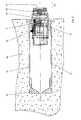
- Fig. 2 a cross section through a pipe vault according to the invention.
- Fig. 1a is a locking device designated 1.
- the locking element has a hook-shaped extension 2 and is pivotally mounted about a pivot axis 3.
- the hook-shaped extension 2 of the locking element 1 engages in the in Fig. 1a Locking position shown a counter-member 4, which has a paragraph 5.
- a closure element 6 is provided, which is guided in a guide, not shown, to perform a movement in the direction of the double arrow 7.
- the closure element 6 is coupled to a first spring element 8 and a second spring element 9. Im in Fig.
- the first spring element 8 and the second spring element 9 each formed by a compressible coil spring, wherein the axes of the two spring elements 8 and 9 are aligned with each other, wherein the first spring element 8 and the second spring element 9 engage on opposite sides of the closure element 6.
- the first spring element 8 and the second spring element 9 cooperate with a drive device, not shown, which is able to exert an obstruction force Fv and an opening force Fo on the spring elements 8 and 9.
- the Verperrkraft Fv and the opening force Fo act here in a common line of action and are directed against each other.
- the drive means is arranged to provide an opening force Fo greater than the shutter force Fv for releasing the lock member 1, and to provide a locking force Fv greater than the opening force Fo for locking the lock member 1.
- the closure member 6 has been moved from the in Fig. 1b shown position shifted to the left to lock in a recess 10 on the locking element 1.
- the recess 10 is in this case designed such that a nose 12 of the closure member 6 positively engages in the recess 10, so that the locking element 1 in the in Fig. 1a shown position can be pressed by no force acting on this from the locking position, as long as the closure element 6 is in the position shown.
- an opening force Fo is now applied to the second spring element 9, so that the closure element 6 of the in Fig. 1a position shown in the in Fig. 1b shown position is shifted to the right, whereby the nose 12 of the closure element 6 engages in the recess 11 of the locking element 1, whereby the locking element 1 with its hook-shaped Extension 2 can be pivoted downwards, whereby the lock is released.
- a pipe vault 13 is shown in section, which is inserted into a bore of a masonry 14.
- the pipe vault 13 has a cylindrical, tubular receiving body 15, which is closed on one side by a cover 16.
- a pipe retainer 17 At the exposed end face of the tubular body 15 is closed by a pipe retainer 17, which is held by means of a sleeve-shaped member 18 in the tubular body 15.
- the pipe containment plug 17 has in its protruding from the masonry 14 area a cup-shaped receiving cross-section 19 in which a reading device 20 is arranged with a contact surface 21 for contact readout of an identification medium such as an I-Button®.
- the reading device 20 cooperates with an electrical evaluation circuit arranged in the interior of the tube retort plug 17 in which the identification data read out by the reading device 20 are checked for any opening authorization. If an opening authorization is detected, a locking element 22 of a locking device integrated in the pipe safety plug 17 is actuated in order to release the lock. In the locked state, a hook-shaped projection on the locking element 22 engages behind a radial shoulder formed by the sleeve-shaped component 18.
- the locking device is in this case according to the in the FIGS. 1a and 1b formed illustrated principle. As soon as the locking element 22 has been released, the pipe-retaining plug 17 can be pulled out of the tubular receiving body 15 in the direction of the arrow 23 in order to release the contents of the tubular receiving body 15 in this way.
- the reading device 20 may preferably be accommodated interchangeably in the cup-shaped receiving cross-section 19, so that the tube vault can be adapted in a simple manner to different identification media technologies.
- the reading device may further be associated with a visual display preferably in the form of a light ring, wherein the color of the light ring can indicate the locking state of the locking device.
Landscapes
- Lock And Its Accessories (AREA)
Applications Claiming Priority (1)
| Application Number | Priority Date | Filing Date | Title |
|---|---|---|---|
| ATA1854/2011A AT511829B1 (de) | 2011-12-20 | 2011-12-20 | Verriegelungseinrichtung sowie Rohrtresor mit einer Verriegelungseinrichtung |
Publications (1)
| Publication Number | Publication Date |
|---|---|
| EP2607596A2 true EP2607596A2 (fr) | 2013-06-26 |
Family
ID=47294826
Family Applications (1)
| Application Number | Title | Priority Date | Filing Date |
|---|---|---|---|
| EP12450046.3A Withdrawn EP2607596A2 (fr) | 2011-12-20 | 2012-11-15 | Système de verrouillage et coffre tubulaire doté d'un système de verrouillage |
Country Status (2)
| Country | Link |
|---|---|
| EP (1) | EP2607596A2 (fr) |
| AT (1) | AT511829B1 (fr) |
Cited By (2)
| Publication number | Priority date | Publication date | Assignee | Title |
|---|---|---|---|---|
| DK178442B1 (da) * | 2012-10-05 | 2016-02-29 | Birepo Aps | Rørformet nøgleboks og fremgangsmåde til fremstilling af denne |
| EP3627458A2 (fr) | 2018-09-19 | 2020-03-25 | Astra Gesellschaft Für Asset Management MbH&Co. Kg | Élément de fermeture et coffre-fort tubulaire doté d'un tel élément de fermeture |
Family Cites Families (3)
| Publication number | Priority date | Publication date | Assignee | Title |
|---|---|---|---|---|
| JP2688429B2 (ja) * | 1988-09-29 | 1997-12-10 | マミヤ・オーピー株式会社 | モータロック金庫 |
| US5060491A (en) * | 1991-01-10 | 1991-10-29 | Smith Neil E | Tubular lock box |
| EP1637673A1 (fr) * | 2004-09-20 | 2006-03-22 | Kaba AG | Dispositif de verrouillage |
-
2011
- 2011-12-20 AT ATA1854/2011A patent/AT511829B1/de not_active IP Right Cessation
-
2012
- 2012-11-15 EP EP12450046.3A patent/EP2607596A2/fr not_active Withdrawn
Cited By (4)
| Publication number | Priority date | Publication date | Assignee | Title |
|---|---|---|---|---|
| DK178442B1 (da) * | 2012-10-05 | 2016-02-29 | Birepo Aps | Rørformet nøgleboks og fremgangsmåde til fremstilling af denne |
| EP3627458A2 (fr) | 2018-09-19 | 2020-03-25 | Astra Gesellschaft Für Asset Management MbH&Co. Kg | Élément de fermeture et coffre-fort tubulaire doté d'un tel élément de fermeture |
| EP3627458A3 (fr) * | 2018-09-19 | 2020-06-17 | Astra Gesellschaft Für Asset Management MbH&Co. Kg | Élément de fermeture et coffre-fort tubulaire doté d'un tel élément de fermeture |
| DE102018123060B4 (de) * | 2018-09-19 | 2025-05-28 | ASTRA Gesellschaft für Asset Management mbH & Co. KG | Verschlusselement und Rohrtresor mit einem solchen Verschlusselement |
Also Published As
| Publication number | Publication date |
|---|---|
| AT511829A4 (de) | 2013-03-15 |
| AT511829B1 (de) | 2013-03-15 |
Similar Documents
| Publication | Publication Date | Title |
|---|---|---|
| EP0861959B1 (fr) | Serrure de sécurité avec contrôle d'accès | |
| EP2673435B1 (fr) | Système de serrure pour bloc-porte à deux vantaux à fonction anti-panique | |
| DE102011008213B4 (de) | Türschlossvorrichtung und Verfahren zum Öffnen einer Türschlossvorrichtung | |
| DE102008063061A1 (de) | Betätigungsvorrichtung für ein elektronisches Türschloß | |
| DE19604442A1 (de) | Sicherheitsvorrichtung für elektronische Schlösser | |
| EP4386158A1 (fr) | Ouvre-porte | |
| DE102008047354A1 (de) | Sperrvorrichtung | |
| EP0779404B1 (fr) | Serrure de sécurité | |
| AT511829B1 (de) | Verriegelungseinrichtung sowie Rohrtresor mit einer Verriegelungseinrichtung | |
| DE19845515C2 (de) | Schließvorrichtung für ein Schloß | |
| EP1662076B1 (fr) | Dispositif d'accouplement pour un dispositif de verrouillage | |
| DE102015000611B4 (de) | Verriegelungsvorrichtung für eine Tür | |
| EP2862992B1 (fr) | Multi-serrure | |
| DE19613638A1 (de) | Schloß | |
| EP1908899A2 (fr) | Système de verrouillage | |
| EP4372190B1 (fr) | Unité de fermeture électronique | |
| AT512320B1 (de) | Rohrtresor mit einer Verriegelungseinrichtung | |
| EP4191002B1 (fr) | Dispositif d'arrêt pour un élément de fermeture ou un élément de commutation | |
| DE19812276C1 (de) | Sicherheitsschloß | |
| EP4441317B1 (fr) | Dispositif de verrouillage électromécanique | |
| DE102008022019B3 (de) | Schließvorrichtung für eine Tür | |
| DE202011000590U1 (de) | Sicherheitsschrank, insbesondere Gefahrstoffschrank | |
| DE3300171C2 (de) | Spann-Riegelsystem | |
| DE202024102679U1 (de) | Elektronisches Schloss und Handhabe mit einem solchen elektronischen Schloss | |
| DE102004030051B3 (de) | Schließvorrichtung |
Legal Events
| Date | Code | Title | Description |
|---|---|---|---|
| AK | Designated contracting states |
Kind code of ref document: A2 Designated state(s): AL AT BE BG CH CY CZ DE DK EE ES FI FR GB GR HR HU IE IS IT LI LT LU LV MC MK MT NL NO PL PT RO RS SE SI SK SM TR |
|
| AX | Request for extension of the european patent |
Extension state: BA ME |
|
| PUAI | Public reference made under article 153(3) epc to a published international application that has entered the european phase |
Free format text: ORIGINAL CODE: 0009012 |
|
| STAA | Information on the status of an ep patent application or granted ep patent |
Free format text: STATUS: THE APPLICATION IS DEEMED TO BE WITHDRAWN |
|
| 18D | Application deemed to be withdrawn |
Effective date: 20160601 |