EP4372190B1 - Unité de fermeture électronique - Google Patents
Unité de fermeture électronique Download PDFInfo
- Publication number
- EP4372190B1 EP4372190B1 EP22208298.4A EP22208298A EP4372190B1 EP 4372190 B1 EP4372190 B1 EP 4372190B1 EP 22208298 A EP22208298 A EP 22208298A EP 4372190 B1 EP4372190 B1 EP 4372190B1
- Authority
- EP
- European Patent Office
- Prior art keywords
- locking
- guide shaft
- coupling element
- knob
- locking unit
- Prior art date
- Legal status (The legal status is an assumption and is not a legal conclusion. Google has not performed a legal analysis and makes no representation as to the accuracy of the status listed.)
- Active
Links
Images

Classifications
-
- E—FIXED CONSTRUCTIONS
- E05—LOCKS; KEYS; WINDOW OR DOOR FITTINGS; SAFES
- E05B—LOCKS; ACCESSORIES THEREFOR; HANDCUFFS
- E05B47/00—Operating or controlling locks or other fastening devices by electric or magnetic means
- E05B47/06—Controlling mechanically-operated bolts by electro-magnetically-operated detents
- E05B47/0611—Cylinder locks with electromagnetic control
- E05B47/0638—Cylinder locks with electromagnetic control by disconnecting the rotor
- E05B47/0646—Cylinder locks with electromagnetic control by disconnecting the rotor radially
- E05B47/0649—Cylinder locks with electromagnetic control by disconnecting the rotor radially with a rectilinearly moveable coupling element
-
- E—FIXED CONSTRUCTIONS
- E05—LOCKS; KEYS; WINDOW OR DOOR FITTINGS; SAFES
- E05B—LOCKS; ACCESSORIES THEREFOR; HANDCUFFS
- E05B3/00—Fastening knobs or handles to lock or latch parts
-
- E—FIXED CONSTRUCTIONS
- E05—LOCKS; KEYS; WINDOW OR DOOR FITTINGS; SAFES
- E05B—LOCKS; ACCESSORIES THEREFOR; HANDCUFFS
- E05B47/00—Operating or controlling locks or other fastening devices by electric or magnetic means
- E05B47/06—Controlling mechanically-operated bolts by electro-magnetically-operated detents
- E05B47/0611—Cylinder locks with electromagnetic control
- E05B47/0615—Cylinder locks with electromagnetic control operated by handles, e.g. by knobs
-
- E—FIXED CONSTRUCTIONS
- E05—LOCKS; KEYS; WINDOW OR DOOR FITTINGS; SAFES
- E05B—LOCKS; ACCESSORIES THEREFOR; HANDCUFFS
- E05B9/00—Lock casings or latch-mechanism casings ; Fastening locks or fasteners or parts thereof to the wing
- E05B9/04—Casings of cylinder locks
- E05B2009/046—Cylinder locks operated by knobs or handles
-
- E—FIXED CONSTRUCTIONS
- E05—LOCKS; KEYS; WINDOW OR DOOR FITTINGS; SAFES
- E05B—LOCKS; ACCESSORIES THEREFOR; HANDCUFFS
- E05B47/00—Operating or controlling locks or other fastening devices by electric or magnetic means
- E05B47/0001—Operating or controlling locks or other fastening devices by electric or magnetic means with electric actuators; Constructional features thereof
- E05B2047/0014—Constructional features of actuators or power transmissions therefor
- E05B2047/0018—Details of actuator transmissions
- E05B2047/0026—Clutches, couplings or braking arrangements
- E05B2047/0031—Clutches, couplings or braking arrangements of the elastic type
Definitions
- the present invention relates to an electronic locking unit for locking a door.
- the electronic locking unit has at least one knob with an identification function, which is attached to a guide shaft.
- the guide shaft is inserted with a free end into an axially continuous cavity of a cylinder profile. After successful identification, the guide shaft interacts with a locking mechanism of the locking unit and enables locking of the locking unit or the door through a rotational movement of the at least one knob with an identification function.
- Such locking cylinders typically have a cylinder housing or cylinder profile and a cylinder core within it, which can be rotated within the housing using a suitable key.
- a locking mechanism e.g., a locking lug or driver that can be rotated relative to the cylinder profile
- lock i.e., unlock or lock
- so-called double cylinders which can be locked on both sides with the appropriate key, are the most common for locking doors in apartments, houses, etc.
- Such locking units can usually be locked keylessly by identifying authorized persons.
- identification of authorized persons for example, numeric codes, programmed fingerprints or other biometric data, RFID cards or chips can be used. Therefore, such locking units usually have an identification function through which entered identification data (e.g. numeric code, fingerprint) or RFID cards or chips brought within range of the locking unit are evaluated.
- the Locking unit is controlled in such a way that locking (i.e. unlocking or locking) of the door or lock is possible or not.
- the locking unit can, for example, have at least one knob with an identification function, which evaluates the entered identification data and/or RFID cards or chips.
- This knob can, for example, be attached to the outside of the door.
- a knob without an identification function is often provided on the inside of the door, to which the locking mechanism (e.g. a locking lug or driver arranged to rotate relative to the cylinder profile) is firmly connected or coupled - usually in a rotationally fixed manner. This allows the locking unit or the door to be locked or unlocked without identification by operating or turning the knob on the inside of the door.
- a knob with an identification function can also be attached to the inside of the door, so that identification is also necessary for locking.
- the at least one knob with identification function of the locking unit is attached to a guide shaft, which - as a cylinder core - is arranged in an axially continuous cavity of a cylinder profile of the locking unit.
- the guide shaft can be rotated, for example, by operating or turning the knob and, after successful identification of a person authorized to access, interacts with the locking mechanism of the locking unit (e.g., a locking lug or driver arranged to rotate relative to the cylinder profile).
- the locking mechanism of the locking unit e.g., a locking lug or driver arranged to rotate relative to the cylinder profile.
- the guide shaft is coupled, for example, mechanically or electromagnetically, to the locking mechanism and can interact with it.
- the interaction of the guide shaft and the locking mechanism means that a rotating movement of the knob with identification function unlocks or locks the locking unit or the door.
- the locking unit is not activated.
- the guide shaft then does not interact with the locking mechanism — for example, the mechanical, electromagnetic, etc. coupling between the guide shaft and the locking mechanism is lost. Locking the locking unit or the door is then not possible.
- the knob When the knob is operated, for example, it can rotate freely, i.e., the knob can be turned 360° "without resistance” without locking the locking unit. Alternatively, movement of the knob without prior, successful identification can also be blocked, and the knob can only be released upon successful identification.
- such electronic locking units often have the disadvantage that only a knob located on the inside of the door - usually a knob without an identification function - can be removed for installation.
- the knob located on the outside of the door when the locking unit is installed - usually the at least one knob with an identification function for the locking function - is usually fixed to the guide shaft for security reasons, and this is arranged in the cylinder profile in such a way that it can be adjusted to a specific door or lock thickness, for example.
- This means that the electronic locking unit can only be inserted into the door lock from the outside of the door towards the inside of the door, and then fastened using a so-called centering screw in the door and by means of the knob attached to the inside of the door.
- This limitation during installation causes problems, especially for doors with protective fittings, which are intended to protect the cylinder and door lock in particular from mechanical manipulation.
- the invention is therefore based on the object of providing an electronic locking unit which enables the door to be locked or bolted in a simple and secure manner even without prior identification and which can be installed easily and efficiently.
- an electronic locking unit for locking a door of the type specified at the outset, in which an actuating element and a coupling element are arranged in the guide shaft, wherein the actuating element is movable relative to the guide shaft and holds the coupling element in a starting position. In the starting position, a portion of the coupling element projects in the radial direction through an outlet in the guide shaft.
- the portion of the coupling element projecting through the outlet is designed such that it interacts with notches provided on an inner side of the locking mechanism of the locking unit in such a way that upon a rotational movement of the at least one knob with identification function without prior identification in a locking direction, the portion projecting through the outlet of the coupling element engages in one of the notches and thereby the locking mechanism of the locking unit is moved along with it, and that upon a rotational movement of the at least one knob with identification function without prior identification in an unlocking direction, the portion of the coupling element projecting through the outlet does not engage in one of the notches.
- the main aspect of the proposed solution is that, without prior identification, the knob with identification function always allows locking or locking by turning the knob in the locking direction, but prevents unauthenticated unlocking or unlocking of the door by turning the knob in the unlocking direction.
- the door can always be locked without identification, which saves time and simplifies the process for an authorized person, for example, since when leaving a house, apartment, etc.
- the knob with identification function which is usually attached to the outside of the door, only needs to be turned in the locking direction to lock the door. If the knob with identification function is turned in the unlocking direction without prior identification, the portion of the coupling element protruding through the opening will not engage in one of the notches.
- knob rotates during movement in the unlocking direction, preventing the door from being unlocked or unlocked, and in particular, preventing unauthorized unlocking. Only upon successful identification of the knob with identification function does the guide shaft couple to the locking mechanism in such a way that turning the knob in the unlocking direction allows the door to be unlocked or unlocked.
- the coupling element can be moved from its initial position to a further position by actuating the actuating element after successful identification.
- the portion of the coupling element which protrudes through the outlet in the guide shaft in the initial position is retracted into the guide shaft, and a further portion of the coupling element protrudes radially out of the guide shaft through a further outlet in the guide shaft.
- two coupling elements can be mounted in the guide shaft instead of one coupling element; in this case, in the further position, a portion of the second coupling element protrudes radially out of the guide shaft, with the second coupling element also being displaceable by the actuating element.
- the further partial area of the coupling element protruding from the guide shaft or the partial area of the second coupling element which protrudes from the guide shaft is designed in such a way that the further partial area of the coupling element or the partial area of the second coupling element interacts with the notches provided on the inside of the locking mechanism of the locking unit in such a way that upon a rotational movement of the at least one knob with identification function In the unlocking direction, the further portion of the coupling element or the portion of the second coupling element engages in one of the notches and the locking mechanism is moved along with it, and that upon rotation of the at least one knob with identification function in the locking direction, the further portion of the coupling element or the portion of the second coupling element does not engage in one of the notches.
- the actuating element moves the coupling element or the two coupling elements in such a way that the further portion of the coupling element or the portion of the second coupling element now protrudes through the further outlet in the guide shaft, through which a coupling between the guide shaft and the locking mechanism is established in such a way that when the knob with identification function is turned in the unlocking direction, the door is unlocked or unlocked. Due to the lack of coupling between the guide shaft and the locking mechanism, a rotation of the knob in the locking direction causes a "spin.”
- the coupling element can be returned from the further position to the starting position due to at least one predeterminable event (e.g. opening and subsequent closing of the door, etc.) or after a predeterminable period of time by actuating the actuating element.
- at least one predeterminable event e.g. opening and subsequent closing of the door, etc.
- two coupling elements are provided instead of one coupling element, these are returned to their respective starting positions by the at least one predeterminable event or after a predeterminable period of time by actuating the actuating element.
- the opening direction of a door is usually determined by a hinge side.
- left-opening door and “right-opening door” are regulated, for example, in Germany by a corresponding DIN standard (DIN 107) and in Austria by a corresponding ⁇ NORM standard ( ⁇ NORM B 5328) or by the standard EN 12519.
- the locking unit can then be installed, for example It can also be determined whether, for example, a first direction of rotation of the knob with identification function is the locking direction and a second direction of rotation of the knob with identification function is the unlocking direction or vice versa.
- At least one portion of the coupling element, which in the initial position protrudes through the outlet from the guide shaft is wedge-shaped. This allows for easy engagement with one of the notches provided on the inside of the locking mechanism when turning in the locking direction, and for rotation when turning in the unlocking direction. Furthermore, it is also advantageous if the further portion of the coupling element or the portion of the second coupling element, which in the further position protrudes through the further outlet from the guide shaft, is also wedge-shaped.
- a preferred embodiment of the electronic locking element provides that the actuating element is designed as a rotary pin, at whose free end a spring pin is eccentrically arranged, wherein the coupling element has a slot into which a free end of the spring pin engages. This allows the coupling element to be easily moved—e.g., by rotating the rotary pin—from the starting position to the further position or from the further position back to the starting position.
- At least one knob with an identification function is configured to move the actuating element using a drive unit. This allows the actuating element to be easily and efficiently actuated upon successful identification in order to move the coupling element from its initial position to the next position. This ideally switches the locking unit from "locking" to "unlocking.” Furthermore, upon the occurrence of at least one predefined event (e.g., opening the door, etc.) or upon the expiration of a predefined period of time, the actuating element can be easily controlled and actuated accordingly to return the coupling element to its initial position, so that only locking or locking of the door is possible.
- at least one predefined event e.g., opening the door, etc.
- a further, practical embodiment of the electronic locking element provides for a locking pin to be arranged in the cylinder profile of the locking element, which is spring-mounted via a spring element.
- the spring action of the spring element presses the locking pin into the axially continuous cavity of the cylinder profile.
- circumferential locking grooves are provided on the circumference of the guide shaft, whereby when the guide shaft is inserted (e.g. when installing the locking unit) into the cavity of the cylinder profile, the locking pin engages in one of the circumferential locking grooves. This allows the locking unit to be easily installed in any door (e.g. with existing security fittings) and in any way - ie from the inside or outside of the door.
- the guide shaft to which at least one knob with identification function is attached, is pushed into the cavity of the cylinder profile during installation and is fixed in the cavity by the locking pin engaging in one of the circumferential locking grooves of the guide shaft due to the spring action of the spring element, so that pulling out the guide shaft or simply removing the knob with identification function is no longer possible.
- the locking pin is advantageously wedge-shaped, with a beveled surface of the wedge-shaped locking pin pointing in the insertion direction of the guide shaft. Another surface of the wedge-shaped locking pin, which is perpendicular to the insertion direction of the guide shaft, points away from the insertion direction.
- the wedge-shaped design of the locking pin allows the guide shaft to be easily pushed further into the cavity until the locking pin engages in a circumferential locking groove of the guide shaft, in which the electronic locking unit is adapted, for example, to a door thickness.
- the circumferential locking grooves are designed in a ramp shape on the side facing the locking pin when inserting the guide shaft into the cavity of the cylinder profile. This significantly facilitates the insertion of the guide shaft and its further insertion.
- an area for tightening the spring element is located inside the door and is ideally only accessible for disassembling the electronic locking unit, for example.
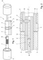
- the electronic locking unit 1 for locking a door is shown schematically and by way of example in a modular state, e.g. for installation in a door.
- the electronic locking unit 1 essentially has a cylinder profile 2, which can be designed, for example, as a profile cylinder profile and can be used in conventional door locks.
- the cylinder profile 2 can also have any other external shape.
- the cylinder profile 2 can consist of two profile parts which are connected via a connecting piece 3.
- a centering bore 4 can be provided in the connecting piece 3, through which the locking unit 1 is fixed after it has been fitted in the door, e.g. with a centering screw.
- the locking unit 1 has a locking mechanism 5, such as a locking lug or driver arranged so as to be rotatable relative to the cylinder profile 2.
- a locking mechanism 5 By actuating the locking mechanism 5 accordingly, the locking unit 1 can lock the door when installed—i.e., ensure that the door is locked or bolted, or unlocked or closed.
- the locking unit 1 has at least one knob 6 with an identification function.
- This knob 6 is intended, for example, for attachment to the outside of the door on the locking unit 1.
- entered identification data e.g., numeric code, fingerprint or other biometric data
- the knob 6 with the identification function can have corresponding devices for data entry (e.g., numeric keypad, fingerprint sensor, etc.).
- RFID cards or chips brought within range of the locking unit 1 can be read and evaluated using the identification function, or identification can be carried out via a mobile phone (e.g., Bluetooth interface).
- the knob 6 with the identification function also have corresponding devices, such as antennas, receiving units, etc.
- the locking unit 1 can also be opened mechanically by means of an emergency key.
- the knob 6 with identification function is attached to a guide shaft 7.
- the guide shaft 7 In the assembled state of the locking unit 1, the guide shaft 7 is arranged in an axially continuous cavity 8 of the cylinder profile, into which the guide shaft 7 is inserted with a free end during assembly and/or installation of the locking unit 1.
- the guide shaft 7 is rotatable by actuating the knob 6 and can interact with the locking mechanism 5 to lock the door.
- a coupling element 9 is provided in the guide shaft 7, which projects with a partial area 10 through an outlet 11 in the guide shaft 7.
- the interaction of the guide shaft 7 or the coupling element 9 with the locking mechanism 5 is explained below using examples shown in the Figures 2 , 3a , 3b and 4 illustrated embodiments of the locking unit 1 are explained in more detail.
- the locking unit 1 also includes a further knob 12, which can be designed, for example, as a rotary knob 12, and is attached, for example, to the inside of a door when the locking unit 1 is assembled.
- This further knob 12 often does not have an identification function and can be connected or coupled, for example, via a connecting shaft 13, to the locking mechanism 5 in a rotationally fixed manner. This allows the door to be easily locked or unlocked without identification by operating the further knob 12.
- the further knob 12, like the knob 6, can also be equipped with an identification function, for example, for security reasons.
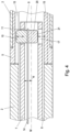
- Figure 2 shows, by way of example and schematically, a longitudinal section through a possible embodiment of the locking unit 1 in the assembled state, wherein an area of the free end of the guide shaft 7 is shown in particular.
- the guide shaft 7 is arranged in the axially continuous cavity 8 of the cylinder profile 2 and can be rotated relative to the cylinder profile 2 via the knob 6 with identification function.
- An actuating element 14 and the coupling element 9 are arranged within the guide shaft 7.
- the coupling element 9 is held in an initial position by the actuating element 14 or by a free end of the actuating element 14. In the initial position, the coupling element 9 with the partial area 10 protrudes in the radial direction through the outlet 11 in the guide shaft 7.
- the partial area 10 of the coupling element 9 is designed such that the partial area 10 interacts with notches 15, which are arranged on an inner side of the locking mechanism 5 of the locking unit 1 - for example in a connecting sleeve, which is connected in a rotationally fixed manner, for example, to a locking lug or a driver.
- the interaction between the partial area 10 of the coupling element 9 and the notches 15 is such that, without prior identification, upon a rotary movement of the knob 6 with identification function and thus a rotary movement of the guide shaft 7 in a blocking direction, the partial area 10 of the coupling element 9 protruding through the outlet 11 engages one of the notches 15 of the locking mechanism 5.
- the locking mechanism 5 of the locking unit 1 is then moved along with it, and the door in which the locking unit 1 is mounted is thereby locked or locked without prior identification. If a rotary movement of the knob 6 with identification function occurs - without prior identification - in a direction opposite to the blocking direction, i.e. in the unlocking direction, the partial area 10 of the coupling element 9 protruding through the outlet 11 interacts with the notches 15 in such a way that the partial area 10 does not engage in one of the notches 15. This means that the knob 6 can be freely rotated because the guide shaft 7 "slips" or ratchets through. Thus, with the locking unit 1, a door can be locked by operating the knob 6 with identification function without prior identification.
- the knob 6 rotates with identification function.
- the partial area 10 of the coupling element 9 can, for example, be wedge-shaped.
- the actuating element 14 or the free end of the actuating element 14 can be designed such that it has an at least slight spring effect, by means of which the partial region 10 of the coupling element 9 is pressed into the outlet 11, in particular during a rotational movement of the guide shaft 7 in the unlocking direction.
- the coupling element 9 can be retracted into the guide shaft 7 by actuating the actuating element 14, for example through the outlet 11.
- the actuating element 14 is movable relative to the guide shaft 7 for this purpose. It can be moved, for example, by a drive unit with a rotational movement D about a central axis M of the guide shaft 7 and/or with a movement T along the central axis M of the guide shaft 7. A movement N of the actuating element 14 normal to the central axis M of the guide shaft is also conceivable.
- the knob 6 with identification function can also be configured to move the actuating element 14 after successful identification by means of the drive unit. A corresponding control or control logic can be provided for this purpose in the knob 6 with identification function.
- the drive unit itself can also be arranged in the knob 6 with identification function.
- the guide shaft 7 is coupled to the locking mechanism 5 in such a way that when the knob 6 with identification function is rotated in the unlocking direction the door can be unlocked.
- This coupling can be electromagnetic, for example, but also - as in the Figures 3a , 3b or 4 as shown by way of example.
- the corresponding control or control logic for this can also be provided in the knob 6 with identification function.
- the locking unit 1 can be unlocked and the door unlocked with an emergency key.
- a turning of the emergency key can be transmitted to the actuating element 14 via a mechanical coupling in such a way that the coupling element 9 is retracted into the guide shaft and the drive unit is mechanically moved along with it.
- a determination of which of the rotation directions of the knob 6 with identification function is the locking direction and which of the rotation directions of the knob 6 with identification function is the unlocking direction can be made, for example, during assembly of the locking unit 1 on a door-specific basis.
- an application can be used, for example, which can be run and accessed on a mobile device (e.g., laptop, mobile phone, etc.).
- the locking unit 1 can be adapted, for example, to right- or left-opening doors, and the starting position of the coupling element 9 can be set accordingly so that the door can be locked or bolted without identification.
- Figure 3a shows, by way of example and schematically, a longitudinal section through a further embodiment of the locking unit 1 in the assembled state, wherein again the area around the free end of the guide shaft 7 is shown.
- the guide shaft 7 is again arranged in the cavity 8 of the cylinder profile 2 and is rotatable relative to the cylinder profile 2 via the knob 6 with identification function.
- the actuating element 14 and a coupling element 9 are again arranged, wherein in the Figure 3a In the exemplary illustration, the coupling element 9 is held in the starting position by the actuating element 14.
- the partial area 10 of the coupling element 9 projects through the outlet 11 in the guide shaft 7.
- the partial area 10 of the coupling element 9 projecting through the outlet 11 interacts with the notches 15 on the inside of the locking mechanism 5 in such a way that when the at least one knob 6 with identification function is rotated in the locking direction, the partial area 10 of the coupling element 9 engages in one of the notches 15 and the locking mechanism 5 is moved along with it, and when the at least one knob 6 with identification function is rotated in the unlocking direction, the partial area 10 of the coupling element 9 does not engage in one of the notches 15.
- a further partial area 16 is provided, which after successful identification - for example by Input of a numeric code, a fingerprint or other biometric data or by means of an RFID card or chip, etc. - is movable from the actuating element 14 through a further outlet 17 in the guide shaft 7 in the direction of movement P.
- the coupling element 9 is moved from the Figure 3a shown starting position is displaced by the actuating element 14 into a further position in the direction of movement P.
- the partial area 10 of the coupling element 9 is then retracted through the outlet 11 into the guide shaft 7. This means that it can no longer interact with the notches 15 on the inside of the locking mechanism 5.
- the further partial area 16 of the coupling element 9 now projects in the radial direction from the further outlet 17 in the guide shaft 7.
- the further partial area 16 of the coupling element 9 is now designed in such a way that it interacts with the notches 15 provided on the inside of the locking mechanism 5 of the locking unit 1 in such a way that when the knob 6 with identification function is rotated in the unlocking direction, the further partial area 16 of the coupling element 9 engages in one of the notches 15 and the locking mechanism 5 is moved along with it, whereas when the at least one knob 6 with identification function is rotated in the locking direction, the further partial area 16 of the coupling element 9 does not engage in one of the notches 15.
- the door is unlocked or unlocked by turning the knob 6 in the unlocking direction, while the knob 6 or the guide shaft 7 "ratchets" or rotates when turned in the locking direction.
- the coupling element 9 is moved from the starting position to the further position by the actuating element 14, which is moved by the drive unit after successful identification.
- the actuating element 14 can, for example, be designed as a rotary pin.
- a spring pin 18 can, for example, be arranged eccentrically at the free end of the rotary pin 14.
- the spring pin 18 can, for example, be arranged in a notch in the surface of the actuating element 14, which runs parallel to the longitudinal axis of the actuating element 14, and can be fastened to the actuating element 14 with a bent end in a force-fitting or form-fitting manner - e.g. by means of a press fit in a blind hole at the end of the notch.
- the coupling element 9 has, for example, a slot 19 into which the free end of the spring pin 18 engages.
- the slot 19 can, for example, be provided centrally between the partial area 10 and the further partial area 16.
- other connection variants positive locking, non-positive locking, etc. are also conceivable, which cause the coupling element 9 to interact or move with the actuating element 14 or the spring pin 18.
- the actuating element 14 performs a rotary movement D (e.g., by 180°) around the central axis M of the guide shaft 7. Due to the eccentric arrangement of the spring pin 18, the rotary movement D is converted into a translatory movement, whereby the coupling element 9 is moved from its initial position to its next position.
- the further partial area 16 of the coupling element 9 can now interact with the notches 15 in such a way that when the knob 6 with identification function is turned in the unlocking direction, the lock is unlocked.
- the coupling element 9 is reset from the further position to the starting position via the actuation of the actuating element 14 due to at least one predeterminable event, such as the opening and/or closing of the door.
- the actuating element 14 can, for example, be rotated counter to the rotational movement D (e.g., by 180°), whereby the coupling element 9 is moved translationally in direction P back to the starting position.
- the partial area 10 of the coupling element 9 protrudes again through the outlet 11 in the guide shaft 7 and, through its interaction with the notches 15, only enables the door to be locked.
- the further partial area 16 of the coupling element 9 is then retracted back into the guide shaft 7.
- a time period (e.g., a few seconds) can also be specified, after which the actuating element 14 returns the coupling element 9 from the further position to the starting position.
- This time period can be set, for example, during assembly and can be provided, for example, in the knob 6 with the identification function as a timer function.
- the coupling element 9 can be mechanically moved from its initial position to the further position using an emergency key, at least in an emergency, such as a malfunction of the identification function on the knob 6, in order to unlock the door.
- an emergency key such as a malfunction of the identification function on the knob 6, in order to unlock the door.
- the rotary movement of the emergency key is transmitted to the actuating element 14 via a mechanical coupling, for example, in order to move the coupling element 9 so that the door can subsequently be unlocked.
- the drive unit which usually moves the actuating element 14 automatically when the identification function is functioning, is also moved mechanically in this case.
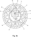
- Figure 3b is also a cross-section through the Figure 3a illustrated embodiment of the electronic locking unit 1 along a section line A - A, wherein the coupling element 9 is held in the starting position by the actuating element 14.
- the partial area 10 of the coupling element 9 projects through the outlet 11 in the guide shaft into the cavity 8 and can interact with the notches 15 of the locking mechanism 5 during rotary movements of the knob 6 with identification function in the locking direction or in the unlocking direction in such a way that when the knob 6 is rotated in the locking direction, the coupling element 9 is coupled and when the knob 6 is rotated in the unlocking direction, the guide shaft 7 rotates or the coupling element is not coupled.
- the partial area 10 of the coupling element 9 is for example - as in Figure 3b shown by way of example - wedge-shaped.
- a vertical edge of the wedge-shaped partial area 10 is arranged in such a way that when the guide shaft 7 rotates in the locking direction, the partial area 10 engages in one of the notches 15.
- the guide shaft 7 is thereby coupled to the locking mechanism 5 and moves the latter during the rotary movement S.
- a ramp-shaped or oblique edge of the wedge-shaped partial area 10 is arranged in such a way that when the guide shaft 7 rotates in the opposite direction to the rotary movement S - i.e. the knob 6 and thus the guide shaft 7 is now rotated in the unlocking direction - the partial area 10 is prevented from engaging in one of the notches 15.
- the further partial area 16 of the coupling element 9, which in the further position - after successful identification - projects through the further outlet 17 from the guide shaft 7 into the cavity 8, can also be wedge-shaped.
- the vertical edge of the wedge-shaped partial area 16 is arranged such that during the rotary movement E of the guide shaft 7 in the unlocking direction, the partial area 16 engages in one of the notches 15 of the locking mechanism 5.
- the rotary movement E of the guide shaft 7 now moves the locking mechanism in the unlocking direction and the door can be unlocked.
- a ramp-shaped or oblique edge of the wedge-shaped partial area 16 is arranged such that during a rotary movement S in the opposite direction of the rotary movement S or in the locking direction, the partial area 16 of the coupling element 9 does not engage in one of the notches 15 of the locking mechanism 5. This means that during a rotational movement E, the section 16 repeatedly slips out of the notches 15 and can also, due to the spring action of the spring pin 18 into the further outlet 17 in the guide shaft 7, thereby preventing engagement in a simple and safe manner.
- two coupling elements 9, 20 can be arranged in the guide shaft 7, which can be moved between the starting position and the further position by actuating the actuating element 14 arranged in the guide shaft 7.
- the starting position is again shown as an example, in which only locking the door is possible without identification.
- the partial area 10 of the coupling element 9 again projects through the outlet 11 of the guide shaft 7 into the cavity 8.
- a second coupling element 20, which can also be moved by actuating the actuating element 14, is retracted into the guide shaft 7 in the starting position.
- the coupling element 9 can interact with the notches 15 on the inside of the locking mechanism 5, whereby the partial area 10 of the coupling element 9 only engages in one of the notches 15 when the knob 6 with identification function is rotated in the locking direction.
- the partial area 10 can again be wedge-shaped for this purpose.
- the actuating element 14 Upon successful identification, the actuating element 14 is then moved by the drive unit in the direction N normal to the central axis M of the guide shaft 7 in order to move the coupling element 9 and thus also the second coupling element 20 from the starting position to the further position. It is also conceivable for this movement to occur via a rotational movement of the actuating element 14.
- the coupling element 9 In the further position, the coupling element 9 is then retracted into the guide shaft 7, while the second coupling element 20 protrudes with a partial area 21 through the further outlet 17 in the guide shaft into the cavity 8 in order to engage in one of the notches 15 upon a rotational movement of the knob 6 with identification function in the unlocking direction and to enable the door to be unlocked or opened.
- the partial area 21 of the second coupling element 20 can, for example, also be wedge-shaped.
- a reset of the two coupling elements 9, 20 from the further position to the starting position can again be carried out event-based and/or upon expiration of a predefined period of time.
- the actuating element 14 or the free end of the actuating element 14 can also be designed such that it has an at least slight spring effect. Due to this spring effect, the partial area 10 of the coupling element 9 in the initial position, in particular during a rotational movement of the guide shaft 7 in the unlocking direction, can be pressed into the outlet 11, or the partial area 21 of the second coupling element 20 in the further position, in particular during a rotational movement of the guide shaft 7 in the locking direction, can be pressed into the further outlet 17, in order to enable a simpler and easier "ratcheting through”. Furthermore, the coupling elements 9, 20 can, for example, - for the transmission of the Movement - positively, non-positively, by means of an adhesive connection, etc., with the actuating element 14. It is also conceivable that the two coupling elements 9, 20 and the actuating element 14 are designed as a single unit.
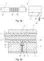
- FIG. 5a This shows Figure 5a the guide shaft 7 of the locking unit 1, to which the knob 6 with identification function (not shown) is attached, as well as the cylinder profile 2 or that part of the cylinder profile 2 of the locking unit 1 which is arranged in the door leaf between the outside of the door and the locking mechanism 5, in a modular or not yet assembled state.
- an outlet 22 e.g. a through hole
- the locking pin 23 is spring-mounted in the outlet 22 via a spring element 24, wherein the locking pin 23 can, for example, have a groove at an end facing the spring element 23, in which groove the spring element 23 engages, for example for a better connection.
- the locking pin 23 and spring element 24 can, for example, be held in the outlet 22 by the connecting piece 3.
- the locking pin 23 is pressed into the cavity 8 in the cylinder profile 2 in the assembled state.
- the locking pin 23 is wedge-shaped, with a beveled surface of the wedge-shaped locking pin 23 pointing in an insertion direction F of the guide shaft 7.
- a vertical surface of the locking pin 23 faces away from the insertion direction E.
- other configurations of the locking pin such as cuboid, cylindrical, etc., are also conceivable.
- the guide shaft has a plurality of circumferential locking grooves 25 on its circumference, which are arranged at a predetermined distance (e.g., 5 mm) from one another.
- the circumferential locking grooves 25 have, for example, a vertical and a ramp-shaped side.
- the guide shaft 7 can be inserted in the insertion direction F into the axially continuous cavity 8 of the cylinder profile 2.
- the side of the circumferential locking grooves 25 pointing in the insertion direction F is ramp-shaped, while the side of the circumferential grooves 25 pointing away from the insertion direction E is vertical. This means that with a wedge-shaped locking pin 23, the ramp-shaped side of the circumferential locking grooves 25 faces the beveled surface of the locking pin 23, and the vertical side points away from the locking pin 23.
- the locking pin 23 engages in one of the circumferential locking grooves 25 of the guide shaft 7. Pulling the guide shaft 7 out of the cavity 8 of the cylinder profile 2 is prevented by the spring action of the spring element 24 then pressing the locking pin 23 into the circumferential locking groove 25.
- the guide shaft 7 can be pushed further into the cavity 8 even after it has clicked into place, until, for example, a desired distance is set between the knob 6 with identification function and, for example, a side of the door in which the locking unit 1 is to be installed.
- a locking pin 23 which is not wedge-shaped or, for example, cuboid-shaped or cylindrical, a length must be correctly set before the guide shaft 7 is inserted into the cavity 8, since with such a design of the locking pin 23, after the locking pin 23 has engaged in one of the circumferential locking grooves 25, it is no longer possible to slide the guide shaft further.
- Figure 5b shows a longitudinal section through the closing unit 1 in the assembled state, in which the guide shaft 7 is inserted into the axially continuous cavity 8 in the cylinder profile 2.
- the locking pin 23 and the spring element 24 are arranged in the outlet 22 in the cylinder profile 2 and are held in the outlet 22, for example, by the connecting piece 3.
- the spring action of the spring element 24 presses the locking pin 23 into the cavity 8 and is engaged in one of the circumferential locking grooves 25 on the circumference of the guide shaft 7.
- the spring action of the spring element 24 and the interaction of the locking pin 23 with the circumferential locking groove 25, in which the locking pin 23 is engaged prevent the guide shaft 7 from being pulled out of the cavity 8.
- the guide shaft 7 can be pushed even further into the cavity 8 in the insertion direction F by the ramp-shaped side of the circumferential locking groove 25, which faces the beveled surface of the locking pin 23. In doing so, the locking pin 23 is pressed into the outlet 22, tensioning the spring element 24. Upon reaching the next circumferential locking groove 25, the locking pin 23 then engages in it due to the spring action of the spring element 24.
- the guide shaft 7 After inserting the guide shaft 7 into the cavity 8 of the cylinder profile 2 and after engaging the locking pin 23 in one of the locking grooves 25 of the guide shaft 7, the guide shaft 7 can only be released from the cavity 8 of the cylinder profile 2 by tensioning the spring element 24.
- an area or access point for tensioning the spring element 24 is located inside the door to prevent unauthorized removal of the knob 6 with identification function or the guide shaft 7.
Landscapes
- Physics & Mathematics (AREA)
- Electromagnetism (AREA)
- Engineering & Computer Science (AREA)
- Mechanical Engineering (AREA)
- Lock And Its Accessories (AREA)
Claims (11)
- Unité de fermeture électronique (1) comportant au moins un bouton (6) avec fonction d'identification, lequel est monté sur un arbre de guidage (7), dans laquelle l'arbre de guidage (7) est disposé avec une extrémité libre dans une cavité (8) traversant axialement un profilé cylindrique (2), et dans laquelle, après une identification réussie, l'arbre de guidage (7) coopère avec un mécanisme de fermeture (5) de l'unité de fermeture et permet un blocage d'une porte par un mouvement de rotation de l'au moins un bouton (6) avec fonction d'identification, caractérisée en ce que dans l'arbre de guidage (7) sont disposés un élément d'actionnement (14), lequel est mobile par rapport à l'arbre de guidage (7), et un élément d'accouplement (9), en ce que l'élément d'actionnement (14) maintient l'élément d'accouplement (9) dans une position initiale, dans laquelle une zone partielle (10) de l'élément d'accouplement (9) fait saillie dans le sens radial à travers une sortie (11) dans l'arbre de guidage (7), et en ce que la zone partielle (10) de l'élément d'accouplement (9) qui fait saillie à travers la sortie (11) est conçue de telle sorte que la zone partielle (10) coopère avec des encoches (15) lesquelles sont pratiquées sur un côté intérieur du mécanisme de fermeture (5) de l'unité de fermeture (1), de telle sorte que lors d'un mouvement de rotation de l'au moins un bouton (6) avec fonction d'identification sans identification préalable dans un sens de blocage, la zone partielle (10) s'enclenche dans l'une des encoches (15) et entraîne le mécanisme de fermeture (5), et que lors d'un mouvement de rotation de l'au moins un bouton (6) avec fonction d'identification sans identification préalable dans un sens de déblocage, aucun enclenchement de la zone partielle (10) dans l'une des encoches (15) n'a lieu.
- Unité de fermeture électronique (1) selon la revendication 1, caractérisée en ce qu 'après une identification réussie, l'élément d'accouplement (9) peut être déplacé dans une autre position par un actionnement de l'élément d'actionnement (14), en ce que dans l'autre position, la zone partielle (10) de l'élément d'accouplement (9) est rétractée dans l'arbre de guidage (7) et une autre zone partielle (16) de l'élément d'accouplement (9) ou une zone partielle (21) d'un second élément d'accouplement (20) monté dans l'arbre de guidage fait saillie de l'arbre de guidage (7) dans le sens radial à travers une autre sortie (17) dans l'arbre de guidage (7), et en ce que l'autre zone partielle (16) de l'élément d'accouplement (9) ou la zone partielle (21) du second élément d'accouplement (20) est conçue de telle sorte, que l'autre zone partielle (16) de l'élément d'accouplement (9) ou la zone partielle (21) du second élément d'accouplement (20) coopère avec les encoches (15) pratiquées sur le côté intérieur du mécanisme de fermeture (5) de l'unité de fermeture (1) de telle sorte, que lors d'un mouvement de rotation de l'au moins un bouton (6) avec fonction d'identification dans le sens de déblocage, l'autre zone partielle (16) de l'élément d'accouplement (9) ou la zone partielle (21) du second élément d'accouplement (20) s'enclenche dans l'une des encoches (15) et entraîne le mécanisme de fermeture (5), et en ce que, lors d'un mouvement de rotation de l'au moins un bouton (6) avec fonction d'identification dans le sens de blocage, aucun enclenchement de l'autre zone partielle (16) de l'élément d'accouplement (9) ou de la zone partielle (21) du second élément d'accouplement (20) dans l'une des encoches (15) n'a lieu.
- Unité de fermeture électronique (1) selon la revendication 2, caractérisée en ce que l'élément d'accouplement (9) peut être ramené de l'autre position à la position initiale par actionnement de l'élément d'actionnement (14) en raison d'au moins un événement pouvant être prédéfini ou après l'écoulement d'une durée pouvant être prédéfinie.
- Unité de fermeture électronique (1) selon l'une des revendications précédentes, caractérisée en ce qu'il est possible de déterminer, à l'aide d'une application ou d'un applicatif, de manière spécifique à la porte, lequel des sens de rotation de l'au moins un bouton (6) avec fonction d'identification est le sens de blocage et lequel des sens de rotation de l'au moins un bouton (6) avec fonction d'identification est le sens de déblocage.
- Unité de fermeture électronique (1) selon l'une des revendications précédentes, caractérisée en ce qu 'au moins l'une zone partielle (10) et l'autre zone partielle (16) de l'élément d'accouplement (9) sont conçues en forme de coin.
- Unité de fermeture électronique (1) selon l'une des revendications précédentes, caractérisée en ce que l'élément d'actionnement (14) est conçu comme une tige rotative à l'extrémité libre de laquelle une tige élastique (18) est disposée de manière excentrée, dans laquelle l'élément d'accouplement (9) présente une fente (19) dans laquelle vient en prise une extrémité libre de la tige élastique (18).
- Unité de fermeture électronique (1) selon l'une des revendications précédentes, caractérisée en ce que l'au moins un bouton (6) avec fonction d'identification est équipé pour déplacer l'élément d'actionnement (14) à l'aide d'une unité d'entraînement.
- Unité de fermeture électronique (1) selon l'une des revendications précédentes, caractérisée en ce que dans le profilé cylindrique (2) est disposée une tige de blocage (23) montée élastiquement par l'intermédiaire d'un élément élastique (24), dans laquelle un effet élastique de l'élément élastique (24) pousse la tige de blocage (23) dans la cavité (8) du profilé cylindrique (2), et en ce que des rainures de blocage périphériques (25) sont prévues sur la périphérie de l'arbre de guidage (7), dans laquelle la tige de blocage (23) s'enclenche dans l'une des rainures de blocage périphériques (25) lors de l'introduction de l'arbre de guidage (7) dans la cavité (8) du profilé cylindrique (2).
- Unité de fermeture électronique (1) selon la revendication 8, caractérisée en ce que la tige de blocage (23) est conçue en forme de coin, dans laquelle une surface biseautée de la tige de blocage (23) en forme de coin est orientée dans un sens d'insertion (F) de l'arbre de guidage (7).
- Unité de fermeture électronique (1) selon l'une des revendications 8 à 9, caractérisée en ce que les rainures de blocage périphériques (25) sont conçues en forme de rampe sur un côté qui est tourné vers la tige de blocage (23) lors de l'insertion de l'arbre de guidage (7).
- Unité de fermeture électronique (1) selon l'une des revendications 8 à 10, caractérisée en ce qu 'après l'introduction de l'arbre de guidage (7) dans la cavité (8) du profilé cylindrique (2) et après l'enclenchement de la tige de blocage (23) dans l'une des rainures de blocage périphériques (25) de l'arbre de guidage (7), l'arbre de guidage (7) peut être libéré de la cavité (8) du profilé cylindrique (2) par serrage de l'élément élastique (24).
Priority Applications (1)
| Application Number | Priority Date | Filing Date | Title |
|---|---|---|---|
| EP22208298.4A EP4372190B1 (fr) | 2022-11-18 | 2022-11-18 | Unité de fermeture électronique |
Applications Claiming Priority (1)
| Application Number | Priority Date | Filing Date | Title |
|---|---|---|---|
| EP22208298.4A EP4372190B1 (fr) | 2022-11-18 | 2022-11-18 | Unité de fermeture électronique |
Publications (3)
| Publication Number | Publication Date |
|---|---|
| EP4372190A1 EP4372190A1 (fr) | 2024-05-22 |
| EP4372190C0 EP4372190C0 (fr) | 2025-05-21 |
| EP4372190B1 true EP4372190B1 (fr) | 2025-05-21 |
Family
ID=84360456
Family Applications (1)
| Application Number | Title | Priority Date | Filing Date |
|---|---|---|---|
| EP22208298.4A Active EP4372190B1 (fr) | 2022-11-18 | 2022-11-18 | Unité de fermeture électronique |
Country Status (1)
| Country | Link |
|---|---|
| EP (1) | EP4372190B1 (fr) |
Families Citing this family (1)
| Publication number | Priority date | Publication date | Assignee | Title |
|---|---|---|---|---|
| SE548041C2 (en) * | 2024-06-10 | 2026-02-10 | Assa Abloy Ab | Arrangement for lock device, and lock device |
Family Cites Families (3)
| Publication number | Priority date | Publication date | Assignee | Title |
|---|---|---|---|---|
| DE19923786A1 (de) * | 1998-06-03 | 1999-12-09 | Dom Sicherheitstechnik | Schließzylinder |
| DE102009003315A1 (de) * | 2009-01-07 | 2010-07-08 | Cestronics Gmbh | Kupplungseinrichtung in einem Schließzylinder bzw. Schließzylinder mit einer Kupplungseinrichtung |
| NL2018421B1 (nl) * | 2017-02-24 | 2018-09-17 | M & C Protect B V | Elektrisch bekrachtigd cilinderslot |
-
2022
- 2022-11-18 EP EP22208298.4A patent/EP4372190B1/fr active Active
Also Published As
| Publication number | Publication date |
|---|---|
| EP4372190A1 (fr) | 2024-05-22 |
| EP4372190C0 (fr) | 2025-05-21 |
Similar Documents
| Publication | Publication Date | Title |
|---|---|---|
| DE102008063061A1 (de) | Betätigungsvorrichtung für ein elektronisches Türschloß | |
| DE19930054C5 (de) | Elektromechanisches Schließsystem | |
| DE29803818U1 (de) | Türbeschlag | |
| DE19604442A1 (de) | Sicherheitsvorrichtung für elektronische Schlösser | |
| EP3219886A1 (fr) | Barre de poussée comprenant un dispositif d'entraînement | |
| EP4372190B1 (fr) | Unité de fermeture électronique | |
| AT501753A4 (de) | Sicherheitseinrichtung für schlösser | |
| EP2345782A1 (fr) | Cylindre anti-panique | |
| EP3095934B1 (fr) | Dispositif de detection d'une position de verrou | |
| EP1908899A2 (fr) | Système de verrouillage | |
| AT511829B1 (de) | Verriegelungseinrichtung sowie Rohrtresor mit einer Verriegelungseinrichtung | |
| WO2023099747A1 (fr) | Dispositif de blocage destiné à un élément de fermeture ou à un élément de commutation | |
| DE102004060477B4 (de) | Schließzylinder | |
| AT4485U1 (de) | Schliesszylinder | |
| AT413844B (de) | Schliesseinrichtung | |
| DE29914093U1 (de) | Elektrisch entriegelbarer Schließmechanismus | |
| EP3396641B1 (fr) | Installation de fermeture | |
| EP3112567B1 (fr) | Verrou avec dispositif d'activation ou de désactivation d'une fonction de jour pour le verrou | |
| DE29923398U1 (de) | Schließsystem für Möbel | |
| EP1338733B1 (fr) | Serrure cylindrique | |
| DE19518491C2 (de) | Anordnung aus zwei Schließzylindern für abzusichernde Zugangsbereiche | |
| EP3889918B1 (fr) | Cylindre de fermeture pour une machine automatique de jeu, machine automatique de jeu et procédé | |
| EP4509681A1 (fr) | Serrure cylindrique | |
| AT512320B1 (de) | Rohrtresor mit einer Verriegelungseinrichtung | |
| DE19603416C1 (de) | Vorrichtung zur Verriegelung eines zwischen zwei Endstellungen bewegbaren, in Verschlußstellung befindlichen Bauteils zum Verschließen einer Zugangsöffnung zu einem von Wänden umschlossenen Raum |
Legal Events
| Date | Code | Title | Description |
|---|---|---|---|
| PUAI | Public reference made under article 153(3) epc to a published international application that has entered the european phase |
Free format text: ORIGINAL CODE: 0009012 |
|
| STAA | Information on the status of an ep patent application or granted ep patent |
Free format text: STATUS: THE APPLICATION HAS BEEN PUBLISHED |
|
| AK | Designated contracting states |
Kind code of ref document: A1 Designated state(s): AL AT BE BG CH CY CZ DE DK EE ES FI FR GB GR HR HU IE IS IT LI LT LU LV MC ME MK MT NL NO PL PT RO RS SE SI SK SM TR |
|
| STAA | Information on the status of an ep patent application or granted ep patent |
Free format text: STATUS: REQUEST FOR EXAMINATION WAS MADE |
|
| 17P | Request for examination filed |
Effective date: 20241009 |
|
| RAP3 | Party data changed (applicant data changed or rights of an application transferred) |
Owner name: CSANK, CHRISTIAN |
|
| RBV | Designated contracting states (corrected) |
Designated state(s): AL AT BE BG CH CY CZ DE DK EE ES FI FR GB GR HR HU IE IS IT LI LT LU LV MC ME MK MT NL NO PL PT RO RS SE SI SK SM TR |
|
| RIN1 | Information on inventor provided before grant (corrected) |
Inventor name: CSANK, CHRISTIAN |
|
| GRAP | Despatch of communication of intention to grant a patent |
Free format text: ORIGINAL CODE: EPIDOSNIGR1 |
|
| STAA | Information on the status of an ep patent application or granted ep patent |
Free format text: STATUS: GRANT OF PATENT IS INTENDED |
|
| INTG | Intention to grant announced |
Effective date: 20250206 |
|
| GRAS | Grant fee paid |
Free format text: ORIGINAL CODE: EPIDOSNIGR3 |
|
| GRAA | (expected) grant |
Free format text: ORIGINAL CODE: 0009210 |
|
| STAA | Information on the status of an ep patent application or granted ep patent |
Free format text: STATUS: THE PATENT HAS BEEN GRANTED |
|
| AK | Designated contracting states |
Kind code of ref document: B1 Designated state(s): AL AT BE BG CH CY CZ DE DK EE ES FI FR GB GR HR HU IE IS IT LI LT LU LV MC ME MK MT NL NO PL PT RO RS SE SI SK SM TR |
|
| REG | Reference to a national code |
Ref country code: GB Ref legal event code: FG4D Free format text: NOT ENGLISH |
|
| REG | Reference to a national code |
Ref country code: CH Ref legal event code: EP |
|
| REG | Reference to a national code |
Ref country code: DE Ref legal event code: R096 Ref document number: 502022004026 Country of ref document: DE |
|
| REG | Reference to a national code |
Ref country code: IE Ref legal event code: FG4D Free format text: LANGUAGE OF EP DOCUMENT: GERMAN |
|
| U01 | Request for unitary effect filed |
Effective date: 20250528 |
|
| U07 | Unitary effect registered |
Designated state(s): AT BE BG DE DK EE FI FR IT LT LU LV MT NL PT RO SE SI Effective date: 20250605 |
|
| PG25 | Lapsed in a contracting state [announced via postgrant information from national office to epo] |
Ref country code: ES Free format text: LAPSE BECAUSE OF FAILURE TO SUBMIT A TRANSLATION OF THE DESCRIPTION OR TO PAY THE FEE WITHIN THE PRESCRIBED TIME-LIMIT Effective date: 20250521 |
|
| PG25 | Lapsed in a contracting state [announced via postgrant information from national office to epo] |
Ref country code: NO Free format text: LAPSE BECAUSE OF FAILURE TO SUBMIT A TRANSLATION OF THE DESCRIPTION OR TO PAY THE FEE WITHIN THE PRESCRIBED TIME-LIMIT Effective date: 20250821 Ref country code: GR Free format text: LAPSE BECAUSE OF FAILURE TO SUBMIT A TRANSLATION OF THE DESCRIPTION OR TO PAY THE FEE WITHIN THE PRESCRIBED TIME-LIMIT Effective date: 20250822 |
|
| PG25 | Lapsed in a contracting state [announced via postgrant information from national office to epo] |
Ref country code: PL Free format text: LAPSE BECAUSE OF FAILURE TO SUBMIT A TRANSLATION OF THE DESCRIPTION OR TO PAY THE FEE WITHIN THE PRESCRIBED TIME-LIMIT Effective date: 20250521 |
|
| PG25 | Lapsed in a contracting state [announced via postgrant information from national office to epo] |
Ref country code: HR Free format text: LAPSE BECAUSE OF FAILURE TO SUBMIT A TRANSLATION OF THE DESCRIPTION OR TO PAY THE FEE WITHIN THE PRESCRIBED TIME-LIMIT Effective date: 20250521 |
|
| PG25 | Lapsed in a contracting state [announced via postgrant information from national office to epo] |
Ref country code: RS Free format text: LAPSE BECAUSE OF FAILURE TO SUBMIT A TRANSLATION OF THE DESCRIPTION OR TO PAY THE FEE WITHIN THE PRESCRIBED TIME-LIMIT Effective date: 20250821 |
|
| PG25 | Lapsed in a contracting state [announced via postgrant information from national office to epo] |
Ref country code: IS Free format text: LAPSE BECAUSE OF FAILURE TO SUBMIT A TRANSLATION OF THE DESCRIPTION OR TO PAY THE FEE WITHIN THE PRESCRIBED TIME-LIMIT Effective date: 20250921 |
|
| U20 | Renewal fee for the european patent with unitary effect paid |
Year of fee payment: 4 Effective date: 20251201 |
|
| PG25 | Lapsed in a contracting state [announced via postgrant information from national office to epo] |
Ref country code: SM Free format text: LAPSE BECAUSE OF FAILURE TO SUBMIT A TRANSLATION OF THE DESCRIPTION OR TO PAY THE FEE WITHIN THE PRESCRIBED TIME-LIMIT Effective date: 20250521 |
|
| PG25 | Lapsed in a contracting state [announced via postgrant information from national office to epo] |
Ref country code: CZ Free format text: LAPSE BECAUSE OF FAILURE TO SUBMIT A TRANSLATION OF THE DESCRIPTION OR TO PAY THE FEE WITHIN THE PRESCRIBED TIME-LIMIT Effective date: 20250521 |
|
| PG25 | Lapsed in a contracting state [announced via postgrant information from national office to epo] |
Ref country code: SK Free format text: LAPSE BECAUSE OF FAILURE TO SUBMIT A TRANSLATION OF THE DESCRIPTION OR TO PAY THE FEE WITHIN THE PRESCRIBED TIME-LIMIT Effective date: 20250521 |
|
| PLBE | No opposition filed within time limit |
Free format text: ORIGINAL CODE: 0009261 |
|
| STAA | Information on the status of an ep patent application or granted ep patent |
Free format text: STATUS: NO OPPOSITION FILED WITHIN TIME LIMIT |
|
| REG | Reference to a national code |
Ref country code: CH Ref legal event code: L10 Free format text: ST27 STATUS EVENT CODE: U-0-0-L10-L00 (AS PROVIDED BY THE NATIONAL OFFICE) Effective date: 20260402 |
|
| 26N | No opposition filed |
Effective date: 20260224 |