EP2613560A1 - Haut-parleur de vibration - Google Patents
Haut-parleur de vibration Download PDFInfo
- Publication number
- EP2613560A1 EP2613560A1 EP12158365.2A EP12158365A EP2613560A1 EP 2613560 A1 EP2613560 A1 EP 2613560A1 EP 12158365 A EP12158365 A EP 12158365A EP 2613560 A1 EP2613560 A1 EP 2613560A1
- Authority
- EP
- European Patent Office
- Prior art keywords
- conductive
- transducer
- vibration speaker
- plate
- alignment
- Prior art date
- Legal status (The legal status is an assumption and is not a legal conclusion. Google has not performed a legal analysis and makes no representation as to the accuracy of the status listed.)
- Withdrawn
Links
Images




Classifications
-
- H—ELECTRICITY
- H04—ELECTRIC COMMUNICATION TECHNIQUE
- H04R—LOUDSPEAKERS, MICROPHONES, GRAMOPHONE PICK-UPS OR LIKE ACOUSTIC ELECTROMECHANICAL TRANSDUCERS; ELECTRIC HEARING AIDS; PUBLIC ADDRESS SYSTEMS
- H04R17/00—Piezoelectric transducers; Electrostrictive transducers
-
- H—ELECTRICITY
- H04—ELECTRIC COMMUNICATION TECHNIQUE
- H04R—LOUDSPEAKERS, MICROPHONES, GRAMOPHONE PICK-UPS OR LIKE ACOUSTIC ELECTROMECHANICAL TRANSDUCERS; ELECTRIC HEARING AIDS; PUBLIC ADDRESS SYSTEMS
- H04R1/00—Details of transducers, loudspeakers or microphones
- H04R1/06—Arranging circuit leads; Relieving strain on circuit leads
-
- H—ELECTRICITY
- H04—ELECTRIC COMMUNICATION TECHNIQUE
- H04R—LOUDSPEAKERS, MICROPHONES, GRAMOPHONE PICK-UPS OR LIKE ACOUSTIC ELECTROMECHANICAL TRANSDUCERS; ELECTRIC HEARING AIDS; PUBLIC ADDRESS SYSTEMS
- H04R2307/00—Details of diaphragms or cones for electromechanical transducers, their suspension or their manufacture covered by H04R7/00 or H04R31/003, not provided for in any of its subgroups
- H04R2307/023—Diaphragms comprising ceramic-like materials, e.g. pure ceramic, glass, boride, nitride, carbide, mica and carbon materials
-
- H—ELECTRICITY
- H04—ELECTRIC COMMUNICATION TECHNIQUE
- H04R—LOUDSPEAKERS, MICROPHONES, GRAMOPHONE PICK-UPS OR LIKE ACOUSTIC ELECTROMECHANICAL TRANSDUCERS; ELECTRIC HEARING AIDS; PUBLIC ADDRESS SYSTEMS
- H04R2307/00—Details of diaphragms or cones for electromechanical transducers, their suspension or their manufacture covered by H04R7/00 or H04R31/003, not provided for in any of its subgroups
- H04R2307/025—Diaphragms comprising polymeric materials
-
- H—ELECTRICITY
- H04—ELECTRIC COMMUNICATION TECHNIQUE
- H04R—LOUDSPEAKERS, MICROPHONES, GRAMOPHONE PICK-UPS OR LIKE ACOUSTIC ELECTROMECHANICAL TRANSDUCERS; ELECTRIC HEARING AIDS; PUBLIC ADDRESS SYSTEMS
- H04R2307/00—Details of diaphragms or cones for electromechanical transducers, their suspension or their manufacture covered by H04R7/00 or H04R31/003, not provided for in any of its subgroups
- H04R2307/027—Diaphragms comprising metallic materials
Definitions
- the present invention generally relates to a vibration speaker, and more particularly to a piezoelectric vibration speaker.
- a speaker is an energy transducer that transforms an electrical signal to mechanical vibration.
- a conventional moving-coil speaker is made up of a magnet, a voice coil, a flexible support and a sound releasing hole. In operation, the electrical signal is transferred to the voice coil, which produces electromagnetic induction, therefore generating an induced current. The induced current energizes the flexible support, and sound is thus produced via the sound releasing hole.
- the conventional moving-coil speaker has been fully developed, it nevertheless occupies large volume, consumes great power and is liable to magnetic field. Therefore, the conventional moving-coil speaker is not adaptable to miniaturization or portability for electronic devices
- the embodiment of the present invention provides a vibration speaker that advantageously occupies small volume, consumes little power, and has a simplified architecture to facilitate easy assembling.
- a vibration speaker includes a top cover, a bottom cover, at least one transducer plate and at least one conductive connector.
- the top cover and the bottom cover define a space.
- the transducer plate is disposed in the defined space, wherein each of the transducer plate includes a conductive plate, a first smart material layer coated on a first surface of the conductive plate, and a first electrode layer formed on the first smart material layer.
- the conductive connector has a protrusion portion that presses on the transducer plate, such that the conductive connector electrically contacts the first electrode layer but not the conductive plate.
- FIG. 1A shows a schematic diagram illustrative of a vibration speaker according to a first embodiment of the present invention.
- the vibration speaker includes a vibration module 10 and a driving module 11.
- the driving module 11 may drive the vibration module 10, for example, via a conductive wire (not shown).
- a vibration plate not shown
- the vibration module 10 and the driving module 10 of the embodiment may have their shapes modified and their relative positions adjusted in accordance with a specific application.
- FIG. 1B shows a disassembled vibration module 10 according to the first embodiment of the present invention.
- the vibration module 10 includes a bottom cover 101, at least one conductive connector 102, at least one transducer plate 103 and a top cover 104.
- the bottom cover 101 and the top cover 104 define a space to accommodate the conductive connector 102 and the transducer plate 103.
- the transducer plate 103 of the embodiment includes a unimorph transducer having a cross-sectional view shown in FIG. 1C , and a perspective view shown in FIG. 1D .
- the transducer plate 103 of the embodiment includes a conductive plate 1031, a first smart material layer 1032 coated on a first (top) surface of the conductive plate 1031, and a first electrode layer 1033 formed on the first smart material layer 1032.
- the first smart material layer 1032 may be made up of a smart material, which includes a piezoelectric material, an electro-active polymer (EAP), a shape memory alloy (SMA), a magnetostrictive material or an electrostrictive material.
- the conductive connector 102 presses on the transducer plate 103.
- the conductive connector 102 has at least one protrusion portion, for example, having a U-shaped cross section. Accordingly, the conductive connector 102 electrically contacts the first electrode layer 1033, but not the conductive plate 1031.
- the driving module 11 drives the transducer plate 103 by electrically connecting, via conductive wires, the conductive connector 102 and the conductive plate 1031, respectively.
- the bottom cover 101 includes two first alignment pins 1011 contacting one end of the transducer plate 103; and the bottom cover 101 also includes two second alignment pins 1012 contacting another end of the transducer plate 103.
- the first alignment pins 1011 are opposite to the second alignment pins 1012.
- the transducer plate 103 of the embedment includes at least one ledge 1031B extended from a center of one side of the transducer plate 103.
- the ledge 1031 B is held between the two first alignment pins 1011, or between the two second alignment pins 1012.
- FIG. 1E shows a perspective view of the conductive connector 102 according to the first embodiment of the present invention.
- the conductive connector 102 of the embodiment presses on the transducer plate 103.
- the conductive connector 102 has one end held between the two first alignment pins 1011, and another end held between the two second alignment pins 1012. Further, two sides of the conductive connector 102 have reentrant curves 1021 respectively, which facilitate holding of the conductive connector 102 between the two first alignment pins 1011.
- the bottom cover 101 of the embodiment may include a third alignment pin 1013, which is adjacent to the first alignment pins 1011 but opposite to the other end of the conductive connector 102.
- the conductive connector 102 is held by the two first alignment pins 1011.
- the conductive connector 102 of the embodiment has a hole 1022 at one end, and the third alignment pin 1013 may pass through the hole 1022.
- FIG. 1F shows a perspective view of a bottom surface of the top cover 104 according to the first embodiment of the present invention.
- the top cover 104 includes at least one pair of first alignment holes 1041 disposed corresponding to the two first alignment pins 1011 of the bottom cover 101; and the top cover 104 also includes at least one pair of second alignment holes 1042 disposed corresponding to the two second alignment pins 1012 of the bottom cover 101.
- the top cover 104 may further include at least one third alignment hole 1043 disposed corresponding to the third alignment pin 1013 of the bottom cover 101.
- the thickness of the protrusion portion of the conductive connector 102 in the embodiment may be properly determined to adjust the distance between the transducer plate 103 and the bottom cover 101, or between the transducer plate 103 and the top cover 104. Accordingly, the transducer plate 103, while be driven by the driving module 11, will not slap the bottom cover 101 or the top cover 104 to produce noise.
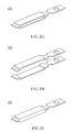
- FIG. 1G shows a perspective view of another conductive connector 102 according to the first embodiment of the present invention.
- the conductive connector 102 of the embodiment has two protrusion portions on the top and bottom respectively to effectively increase its thickness such that the transducer plate 103 can be prevented from slapping the bottom cover 101 or the top cover 104.
- FIG. 1G may be made up of two composing elements as illustrated in FIG. 1H .
- the space between two protrusion portions of FIG. 1G may be solid as illustrated in FIG. 1I .
- a protrusion 1014 ( FIG. 1B or FIG. 1F ) may be disposed, corresponding to the conductive connector 102, on the bottom cover 101 or the top cover 104 such that the transducer plate 103 can be prevented from slapping the bottom cover 101 or the top cover 104.
- the positive electrode and the negative electrode of the embodiment may be connected to the driving module 11 according to the following schemes.
- the first electrode connecting scheme adopts soldering technique by applying solder on the conductive connectors 102 to make them electrically connected, and applying solder on the ledge 1031B of the transducer plates 103 to make them electrically connected.
- the second electrode connecting scheme uses conductive ring 105, as shown in FIG. 2A , which is attached to the third alignment pin 1013 and is electrically connected with the conductive connectors 102, such that the conductivity of the first electrode layer 1033 may thus be derived.
- the conductive ring 105 of the embodiment is not restricted to that shown in FIG. 2A , but may be properly modified as exemplified in FIG. 2B, FIG. 2C or FIG.
- the third electrode connecting scheme uses the third alignment pin 1013 with conductivity, or, in other words, a conductive third alignment pin 1013.
- FIG. 2E shows a screw, which may pass through the third alignment hole 1043 of the top cover 104 and then screws into a screw hole in the third alignment pin 1013.
- the conductive third alignment pin 1013 may be a screw pin as shown in FIG. 2F , or a screw spring as shown in FIG. 2G .
- the conductive connector 102 may act as a fixing point for the transducer plate 103, and a vibration pivot point for the transducer plate 103 while being driven.
- the transducer plate 103 vibrates after being driven by the driving module 11, an inertial force is generated at (the pivot/fixing point) of the conductive connector 102, and the inertial force is then propagated to the bottom cover 101 and the vibration plate to produce sound.
- the conductive connector 102 may further fix the transducer plate 103.
- FIG. 3A shows a disassembled vibration module according to a second embodiment of the present invention.
- the vibration module of the second embodiment is similar to the first embodiment ( FIG. 1B ), with the exception that the transducer plate 103 of the present embodiment uses a single bimorph transducer.
- FIG. 3B shows a cross-sectional view of the bimorph transducer according to the second embodiment of the present invention.
- the transducer plate 103 of the embodiment includes a conductive plate 1031, a first smart material layer 1032 coated on a first (top) surface of the conductive plate 1031, and a first electrode layer 1033 formed on the first smart material layer 1032.
- the transducer plate 103 of the embodiment also includes a second smart material layer 1034 coated on a second (bottom) surface of the conductive plate 1031, and a second electrode layer 1035 formed below the second smart material layer 1034.
- the embodiment includes two conductive connectors 102 that are disposed above and below the transducer plate 103, respectively, to contact the first electrode layer 1033 and the second electrode layer 1035, respectively.
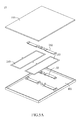
- FIG. 4 shows a perspective view of a disassembled vibration module 10 according to a third embodiment of the present invention.
- the present embodiment is similar to the second embodiment, with the exception that the present embodiment uses two (or more) bimorph transducers as the transducer plates 103 that are (vertically) stacked up; and at least one conductive connector 102 is disposed above or below adjacent transducer plate 103, or between neighboring transducer plates 103.
- the embodiment may adopt a plurality of conductive rings 105 ( FIG. 2A ), which are attached to the third alignment pin 1013, and each of which is disposed between neighboring conductive connectors 102 to make the conductive connectors 102 electrically connected.
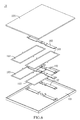
- FIG. 5A shows a perspective view of a disassembled vibration module 10 according to a fourth embodiment of the present invention.
- the present embodiment is similar to the second embodiment, with the exception that the present embodiment uses two (or more) bimorph transducers that are (horizontally) aligned in parallel, and the conductive connectors 102 are disposed above and below the transducer plates 103.
- a third alignment pin 1013 may be shared with two (horizontally) adjacently aligned transducer plates 103.
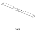
- two original conductive connectors 102 may be integrated to a single conductive connector 102, as shown in FIG. 5B .
- the embodiment may adopt the conductive rings 105 ( FIG. 2A ), which is attached to the third alignment pin 1013, and is electrically connected to the conductive connector 102.
- the embodiments discussed above may be individually used or be used in combination.
- the third embodiment ( FIG. 4 ) and the fourth embodiment ( FIG. 5A ) are used in combination, that is, two (or more) transducer plates 103 that are (vertically) stacked up, and two (or more) transducer plates 103 that are (horizontally) aligned in parallel.
Landscapes
- Physics & Mathematics (AREA)
- Engineering & Computer Science (AREA)
- Acoustics & Sound (AREA)
- Signal Processing (AREA)
- Piezo-Electric Transducers For Audible Bands (AREA)
Applications Claiming Priority (1)
| Application Number | Priority Date | Filing Date | Title |
|---|---|---|---|
| TW101100521A TW201330642A (zh) | 2012-01-05 | 2012-01-05 | 振動喇叭 |
Publications (1)
| Publication Number | Publication Date |
|---|---|
| EP2613560A1 true EP2613560A1 (fr) | 2013-07-10 |
Family
ID=45787118
Family Applications (1)
| Application Number | Title | Priority Date | Filing Date |
|---|---|---|---|
| EP12158365.2A Withdrawn EP2613560A1 (fr) | 2012-01-05 | 2012-03-07 | Haut-parleur de vibration |
Country Status (5)
| Country | Link |
|---|---|
| US (1) | US20130177183A1 (fr) |
| EP (1) | EP2613560A1 (fr) |
| JP (1) | JP2013141191A (fr) |
| CN (1) | CN103200505A (fr) |
| TW (1) | TW201330642A (fr) |
Families Citing this family (3)
| Publication number | Priority date | Publication date | Assignee | Title |
|---|---|---|---|---|
| US20160296849A9 (en) * | 2012-05-22 | 2016-10-13 | Hasbro, Inc. | Building Elements with Sonic Actuation |
| EP3092818A1 (fr) * | 2014-01-07 | 2016-11-16 | Sony Corporation | Casque à écouteurs équipé d'un matériau pouvant changer de taille |
| EP3384685B1 (fr) * | 2015-12-04 | 2019-09-11 | Harman Becker Automotive Systems GmbH | Haut-parleur électroactif |
Citations (5)
| Publication number | Priority date | Publication date | Assignee | Title |
|---|---|---|---|---|
| JPH05111085A (ja) * | 1991-10-17 | 1993-04-30 | Matsushita Electric Ind Co Ltd | セラミツクレシーバ |
| EP0656665A1 (fr) * | 1993-11-26 | 1995-06-07 | Ngk Insulators, Ltd. | Dispositif piézoélectrique |
| EP0825799A2 (fr) * | 1996-08-13 | 1998-02-25 | Murata Manufacturing Co., Ltd. | Transducteur électroacoustique avec dimensions réduites et borne améliorée |
| US6445108B1 (en) * | 1999-02-19 | 2002-09-03 | Murata Manufacturing Co., Ltd. | Piezoelectric acoustic component |
| US6587567B1 (en) * | 1997-01-06 | 2003-07-01 | Murata Manufacturing Co., Ltd. | Piezoelectric electroacoustic transducer |
Family Cites Families (4)
| Publication number | Priority date | Publication date | Assignee | Title |
|---|---|---|---|---|
| US4985926A (en) * | 1988-02-29 | 1991-01-15 | Motorola, Inc. | High impedance piezoelectric transducer |
| DE68919100T2 (de) * | 1988-03-17 | 1995-03-09 | Tdk Corp | Piezoelektrischer Summer und Verfahren zu dessen Herstellung. |
| JP2005045691A (ja) * | 2003-07-24 | 2005-02-17 | Taiyo Yuden Co Ltd | 圧電振動装置 |
| KR20120036631A (ko) * | 2010-10-08 | 2012-04-18 | 삼성전자주식회사 | 압전형 마이크로 스피커 및 그 제조방법 |
-
2012
- 2012-01-05 TW TW101100521A patent/TW201330642A/zh unknown
- 2012-01-19 CN CN2012100177214A patent/CN103200505A/zh active Pending
- 2012-03-07 EP EP12158365.2A patent/EP2613560A1/fr not_active Withdrawn
- 2012-03-07 US US13/414,380 patent/US20130177183A1/en not_active Abandoned
- 2012-03-14 JP JP2012057150A patent/JP2013141191A/ja active Pending
Patent Citations (5)
| Publication number | Priority date | Publication date | Assignee | Title |
|---|---|---|---|---|
| JPH05111085A (ja) * | 1991-10-17 | 1993-04-30 | Matsushita Electric Ind Co Ltd | セラミツクレシーバ |
| EP0656665A1 (fr) * | 1993-11-26 | 1995-06-07 | Ngk Insulators, Ltd. | Dispositif piézoélectrique |
| EP0825799A2 (fr) * | 1996-08-13 | 1998-02-25 | Murata Manufacturing Co., Ltd. | Transducteur électroacoustique avec dimensions réduites et borne améliorée |
| US6587567B1 (en) * | 1997-01-06 | 2003-07-01 | Murata Manufacturing Co., Ltd. | Piezoelectric electroacoustic transducer |
| US6445108B1 (en) * | 1999-02-19 | 2002-09-03 | Murata Manufacturing Co., Ltd. | Piezoelectric acoustic component |
Also Published As
| Publication number | Publication date |
|---|---|
| CN103200505A (zh) | 2013-07-10 |
| TW201330642A (zh) | 2013-07-16 |
| JP2013141191A (ja) | 2013-07-18 |
| US20130177183A1 (en) | 2013-07-11 |
Similar Documents
| Publication | Publication Date | Title |
|---|---|---|
| US8625824B2 (en) | Flat speaker unit and speaker device therewith | |
| US10250993B1 (en) | Miniature speaker | |
| US9154884B2 (en) | Electro-acoustic transducer | |
| US9475094B2 (en) | Vibration generating apparatus | |
| TW201308866A (zh) | 能量轉換模組 | |
| CN209805645U (zh) | 一种激励器及电子产品 | |
| EP2613561A1 (fr) | Haut-parleur de vibration | |
| US20170034629A1 (en) | Speaker | |
| US20180048962A1 (en) | Vibration output apparatus and portable electronic device comprising vibration output apparatus | |
| JP2017098930A (ja) | ロングストローク型スピーカ | |
| JP6053794B2 (ja) | 音響発生器、音響発生装置および電子機器 | |
| US9660172B2 (en) | Vibrator | |
| EP2613560A1 (fr) | Haut-parleur de vibration | |
| CN211909151U (zh) | 扬声器的磁性结构 | |
| KR101588922B1 (ko) | 압전 액추에이터를 포함하는 진동발생장치 | |
| US10602278B2 (en) | Speaker | |
| JP5806401B2 (ja) | 携帯型電子機器用カバーおよびそれを用いた携帯型電子装置 | |
| CN103444207A (zh) | 振荡器和电子设备 | |
| CN210609695U (zh) | 电子设备 | |
| CN210202072U (zh) | 电声转换器件及应用其的电子设备 | |
| CN218162854U (zh) | 压电换能器及电子设备 | |
| CN117977999A (zh) | 驱动单元、压电马达、摄像模组和电子设备 | |
| WO2010023755A1 (fr) | Microphone et casque d'écoute à conduction osseuse | |
| KR20230087169A (ko) | 에너지 하베스터 및 이를 포함하는 표시장치 | |
| KR100510071B1 (ko) | 압전 진동체를 이용한 전자음향장치 |
Legal Events
| Date | Code | Title | Description |
|---|---|---|---|
| PUAI | Public reference made under article 153(3) epc to a published international application that has entered the european phase |
Free format text: ORIGINAL CODE: 0009012 |
|
| 17P | Request for examination filed |
Effective date: 20130411 |
|
| AK | Designated contracting states |
Kind code of ref document: A1 Designated state(s): AL AT BE BG CH CY CZ DE DK EE ES FI FR GB GR HR HU IE IS IT LI LT LU LV MC MK MT NL NO PL PT RO RS SE SI SK SM TR |
|
| AX | Request for extension of the european patent |
Extension state: BA ME |
|
| STAA | Information on the status of an ep patent application or granted ep patent |
Free format text: STATUS: THE APPLICATION IS DEEMED TO BE WITHDRAWN |
|
| 18D | Application deemed to be withdrawn |
Effective date: 20130713 |