EP0825799A2 - Transducteur électroacoustique avec dimensions réduites et borne améliorée - Google Patents
Transducteur électroacoustique avec dimensions réduites et borne améliorée Download PDFInfo
- Publication number
- EP0825799A2 EP0825799A2 EP97401914A EP97401914A EP0825799A2 EP 0825799 A2 EP0825799 A2 EP 0825799A2 EP 97401914 A EP97401914 A EP 97401914A EP 97401914 A EP97401914 A EP 97401914A EP 0825799 A2 EP0825799 A2 EP 0825799A2
- Authority
- EP
- European Patent Office
- Prior art keywords
- piezoelectric
- plate
- metallic plate
- lead
- casing
- Prior art date
- Legal status (The legal status is an assumption and is not a legal conclusion. Google has not performed a legal analysis and makes no representation as to the accuracy of the status listed.)
- Withdrawn
Links
Images

Classifications
-
- H—ELECTRICITY
- H04—ELECTRIC COMMUNICATION TECHNIQUE
- H04R—LOUDSPEAKERS, MICROPHONES, GRAMOPHONE PICK-UPS OR LIKE ACOUSTIC ELECTROMECHANICAL TRANSDUCERS; ELECTRIC HEARING AIDS; PUBLIC ADDRESS SYSTEMS
- H04R17/00—Piezoelectric transducers; Electrostrictive transducers
Definitions
- the present invention relates generally to piezoelectric devices, and more particularly to piezoelectric electro-acoustic transducers for use in piezoelectric sounders, piezoelectric telephone receivers and other devices.
- the invention also relates to a piezoelectric electro-acoustic transducer having an improved terminal for interconnection with a piezoelectric diaphragm.
- PJPA Japanese Patent Application
- No. 5-111085 discloses a ceramic receiver which includes a piezoelectric diaphragm that consists of a lamination of a metal plate and a piezoelectric element on the surface thereof and that is contained inside a casing, wherein a metal terminal is connected at one end thereof to the piezoelectric diaphragm and the other end of the metal terminal extends to outside of the casing. Interconnection of the metal terminals to the piezoelectric diaphragm is done by soldering or spring-contact techniques.
- a piezoelectric telephone receiver is disclosed in PUJPA No. 7-203590, wherein a piezoelectric diaphragm consists of a metal plate and a piezoelectric ceramic plate laminated on one surface thereof, and is contained inside a casing while associated lead wires are coupled to the piezoelectric diaphragm such that the lead wires extend to outside of the casing.
- the prior art piezoelectric electro-acoustic transducers have been structured such that the piezoelectric diaphragm is supported inside the casing while the piezoelectric diaphragm is connected to one end of a lead wire or a metal terminal with the lead wire or metal terminal being elongated to extend outside of the casing.
- the preferred embodiments of the invention provide an improved piezoelectric electro-acoustic transducer having an improved structure for suppressing or eliminating a negative influence on the sound pressure and resonant frequency characteristics caused by an electrode takeout device, even though the electro-acoustic transducer has a substantially reduced size and thickness.
- the preferred embodiments of the present invention provide a piezoelectric electro-acoustic transducer which includes a piezoelectric diaphragm having a piezoelectric ceramic plate and a metallic plate.
- the ceramic plate preferably has a thickness of about 100 ⁇ m or less whereas the metallic plate preferably has a thickness of about 100 ⁇ m or less.
- the transducer also includes a casing for supporting and storing the piezoelectric diaphragm.
- the piezoelectric diaphragm has an electrode disposed on a surface opposite to at least the metallic plate while metal terminals are arranged to be in contact with the metallic plate of the piezoelectric diaphragm and the electrode, respectively.
- the modulus of elasticity X is specifically determined to fall within a desired range given as: b ⁇ h 3 ⁇ E 4 ⁇ L 3 ⁇ 100 (N/m), where, E (N/m) is the Young's modulus of the metal terminal disposed in contact with the electrode on the piezoelectric ceramic plate, b (mm) is the width of a portion of the metal terminal extending from the inside of the casing to the outside thereof, h (mm) is the thickness of the metal terminal, and L (mm) is the length of the metal terminal.
- the piezoelectric electro-acoustic transducer of the preferred embodiments of the present invention includes a metal terminal comprised of a specific component part which achieves the above criteria in physical nature and in size; in particular, it has been discovered that such metal terminal may be used as the metal terminal to be disposed in contact with the electrode provided on a piezoelectric ceramic plate of the piezoelectric diaphragm.
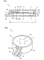
- Fig. 1 is a longitudinal cross-sectional view of a piezoelectric electro-acoustic transducer in accordance with one preferred embodiment of the present invention.
- Fig. 2 is a perspective view of the piezoelectric electro-acoustic transducer shown in Fig. 1.
- Fig. 3 is a side view of one metal terminal disposed in contact with a piezoelectric element of the transducer.
- Fig. 4 is a cross-sectional view of the metal terminal taken along line A-A of Fig. 3.
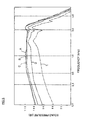
- Fig. 5 is a graph showing the sound pressure versus frequency characteristics of several working samples of the piezoelectric electro-acoustic transducer as manufactured using five different types of metal terminals.
- Fig. 6 is a graph showing the correlation of the modulus of elasticity versus sound pressure at 1 kHz.
- a piezoelectric electro-acoustic transducer device in accordance with one preferred embodiment of the invention is generally designated by reference numeral 1.
- the piezoelectric electro-acoustic transducer 1 includes a piezoelectric diaphragm 2, and a casing 3 which holds or stores therein the piezoelectric diaphragm 2.
- the piezoelectric diaphragm 2 is preferably constructed from a disk-like metal plate 4 and a disk-like piezoelectric element 5 which preferably has a diameter less than that of the metal plate 4 and is laminated by adhesion on the upper surface of the metal plate 4.
- the metal plate 4 may be made of a chosen metal or metal alloy, including stainless steel, brass, Ni-alloy and other suitable materials. In one preferred embodiment, the metal plate 4 preferably measures about 100 ⁇ m or less in thickness.
- the piezoelectric element 5 may be constituted by a structure in which an electrode (not shown) is formed on the upper surface of a disk-like piezoelectric ceramic plate.
- This piezoelectric ceramic plate may be made of either suitable piezoelectric ceramics such as lead zirconate titanate-based piezoelectric ceramics or piezoelectric single-crystals such as quartz crystal.
- a plate which has a thickness of about 100 ⁇ m or less is preferably used. The reason for this is that if the thickness is greater than 100 ⁇ m then it will no longer be possible to accomplish sufficient suppression of a decrease in sound pressure as well as a variation in resonance frequency, even with use of the metal terminals which satisfy the criteria as defined by the formula described later.
- this electrode may be formed by known electrode fabrication techniques.
- the casing 3 preferably has a substantially tubular or cylindrical casing member 6 of a decreased height having an opening at its upper end and a bottom at its lower end, and a lid member 7 which is secured to the casing member 6 so as to block or close an opening 6a of the casing member 6.
- the casing member 6 and lid member 7 may be made of a chosen dielectric material, such as insulative ceramics, synthetic resin, or other suitable materials.
- a step-like portion 6b is formed on the inner wall of the casing member 6 at a vertical midpoint position, allowing the piezoelectric diaphragm 2 to be supported at the step-like portion 6b. More specifically, the piezoelectric diaphragm 2 is mounted on the step-like portion 6b for rigid support of the piezoelectric diaphragm 2 between a downwardly extended ring-like section 7a of the lid member 7 and the step-like portion 6b.
- a cut-away portion 6c is formed at part of the circumferential wall of the casing member 6, allowing metal terminals 8, 9 to extend to the outside of the casing member 6.
- the casing member 6 also has an external terminal-edge support 6e laterally projecting from the outer circumferential wall thereof providing fixed support for two spaced-apart terminal ends of the parallel elongate metal terminals 8, 9 on the upper surface thereof as best illustrated in Fig. 2.
- the lid member 7 is also provided with a plurality of through holes 7b, which are provided for externally radiating sound waves and for receiving incoming sound waves. Similarly, a plurality of through holes 6d are formed in the bottom plane of the casing member 6 for the same reasons.
- the metal terminal 8 is disposed in contact with the electrode on the upper surface of the piezoelectric element 5 whereas the metal terminal 9 is disposed in contact with the metal plate 2.
- the contacts are achieved by use of solder 10a, 10b in this preferred embodiment; however, the same may alternatively be attained using other possible contact methods and structures including a method of using conductive adhesive instead of the solder, a welding technique, and other suitable contact-establishing techniques.
- the metal terminal 9 may be made of suitable metals or alloys.
- a feature of the present preferred embodiment lies in that the metal terminal 8 is specifically arranged in such a manner that the modulus of elasticity X is specifically determined to fall within a range as defined by: b ⁇ h 3 ⁇ E 4 ⁇ L 3 ⁇ 100 (N/m), where E (N/m 3 ) is the Young's modulus of the metal terminal disposed in contact with the piezoelectric element, b (mm) is the width of a part of the metal terminal extending from the inside of the casing to the outside thereof, h (mm) is the thickness of the metal terminal, and L (mm) is the length of the metal terminal.
- a piezoelectric diaphragm 2 was prepared from a metal plate 4 made of Ni alloy and measuring 19.4 mm in diameter and 0.05 mm in thickness, and a PZT piezoelectric element 5 of 14 mm diameter x 0.05 mm thickness was laminated on the upper surface of metal plate 4.
- the casing 3 was made of PBT (polybutylene terphthalate) resin and measured 18.8 mm in inner diameter at the positions lower in level than the step-like portion 6b, 21.5 mm in outer diameter A of Fig. 1, and 1.8 mm in height. Note that the height position from the bottom plane of the step-like portion 6b was 0.8 mm.
- piezoelectric electro-acoustic transducers Five different types were manufactured using the piezoelectric diaphragm 2 and casing 3 having the dimensions as stated supra and also using for the metal terminal 8, several metal terminals A to E shown in the Table below. Additionally, for the metal terminal 9, brass was used.
- the metal terminal 8 preferably has a bent section 8a in the vicinity of a certain part to be brought into contact with the piezoelectric element 5, has a linear section 8b extending from this bent section 8a to the outside of the casing 3, and has a shape wherein a second bent section 8c is formed at an external edge side of the linear section 8b.
- the length L of the metal terminal 8 may refer to the length of the linear section 8b elongated from the bent section 8a toward the outside of the casing 3 as shown in Fig. 3.
- the plate thickness h and width b may refer to the thickness and width dimensions at the linear section 8b (see Fig. 4).
- Fig. 6 the relation of the modulus of elasticity versus sound pressure at 1 kHz is shown in Fig. 6. As can be seen from Fig. 6, as the modulus of elasticity increases beyond 100 at 1 kHz, the sound pressure decreases significantly. Therefore, it has been found that it is required that the modulus of elasticity be less than or equal to 100 at 1 kHz in order to eliminate a decrease in sound pressure.
- piezoelectric diaphragm 2 having a ring-like shape
- piezoelectric diaphragms of other shapes may alternatively be used such as those having a substantially rectangular shape; it is also pointed out that the planar shape of the casing 3 may be freely modified in conformity with the planar shape of the piezoelectric diaphragm when necessary.
Landscapes
- Physics & Mathematics (AREA)
- Engineering & Computer Science (AREA)
- Acoustics & Sound (AREA)
- Signal Processing (AREA)
- Piezo-Electric Transducers For Audible Bands (AREA)
- Telephone Set Structure (AREA)
Applications Claiming Priority (6)
| Application Number | Priority Date | Filing Date | Title |
|---|---|---|---|
| JP21389096 | 1996-08-13 | ||
| JP21389096 | 1996-08-13 | ||
| JP213890/96 | 1996-08-13 | ||
| JP23807596A JP3233041B2 (ja) | 1996-08-13 | 1996-09-09 | 圧電型電気音響変換器 |
| JP23807596 | 1996-09-09 | ||
| JP238075/96 | 1996-09-09 |
Publications (2)
| Publication Number | Publication Date |
|---|---|
| EP0825799A2 true EP0825799A2 (fr) | 1998-02-25 |
| EP0825799A3 EP0825799A3 (fr) | 2005-03-09 |
Family
ID=26520035
Family Applications (1)
| Application Number | Title | Priority Date | Filing Date |
|---|---|---|---|
| EP97401914A Withdrawn EP0825799A3 (fr) | 1996-08-13 | 1997-08-11 | Transducteur électroacoustique avec dimensions réduites et borne améliorée |
Country Status (5)
| Country | Link |
|---|---|
| US (1) | US5955824A (fr) |
| EP (1) | EP0825799A3 (fr) |
| JP (1) | JP3233041B2 (fr) |
| CN (1) | CN1139299C (fr) |
| NO (1) | NO973701L (fr) |
Cited By (2)
| Publication number | Priority date | Publication date | Assignee | Title |
|---|---|---|---|---|
| EP2613560A1 (fr) * | 2012-01-05 | 2013-07-10 | Chief Land Electronic Co. Ltd. | Haut-parleur de vibration |
| EP2613561A1 (fr) * | 2012-01-05 | 2013-07-10 | Chief Land Electronic Co. Ltd. | Haut-parleur de vibration |
Families Citing this family (15)
| Publication number | Priority date | Publication date | Assignee | Title |
|---|---|---|---|---|
| US6445108B1 (en) * | 1999-02-19 | 2002-09-03 | Murata Manufacturing Co., Ltd. | Piezoelectric acoustic component |
| DE10013673C2 (de) * | 2000-03-20 | 2002-02-07 | Siemens Audiologische Technik | Mikromechanischer elektroakustischer Wandler |
| JP3501100B2 (ja) * | 2000-05-15 | 2004-02-23 | 株式会社村田製作所 | 超音波送受波器 |
| JP3706903B2 (ja) * | 2000-08-10 | 2005-10-19 | 独立行政法人産業技術総合研究所 | フレキシブル高感度セラミックスセンサー |
| JP2003078995A (ja) * | 2001-09-03 | 2003-03-14 | Taiyo Yuden Co Ltd | 圧電音響装置 |
| JP4037413B2 (ja) * | 2005-01-13 | 2008-01-23 | Tdk株式会社 | 圧電サウンダ |
| EP2787747B1 (fr) * | 2011-11-29 | 2017-06-28 | Sumitomo Riko Company Limited | Haut-parleur polymère |
| JP5578218B2 (ja) * | 2012-09-25 | 2014-08-27 | Tdk株式会社 | 圧電サウンダ |
| CN103796120A (zh) * | 2013-10-28 | 2014-05-14 | 广州市番禺奥迪威电子有限公司 | 一种压电式受话器 |
| US9705069B2 (en) * | 2013-10-31 | 2017-07-11 | Seiko Epson Corporation | Sensor device, force detecting device, robot, electronic component conveying apparatus, electronic component inspecting apparatus, and component machining apparatus |
| FR3022674B1 (fr) * | 2014-06-18 | 2019-12-13 | Iem Sarl | Borne de detection comprenant un transducteur piezoelectrique fixe a une membrane liee a une structure de butee |
| JP6222185B2 (ja) * | 2015-08-11 | 2017-11-01 | Tdk株式会社 | 圧電発音体 |
| US11950051B2 (en) * | 2017-11-21 | 2024-04-02 | Nitto Denko Corporation | Piezoelectric speaker |
| JP7524658B2 (ja) * | 2020-07-30 | 2024-07-30 | セイコーエプソン株式会社 | 流体デバイス |
| JP7484534B2 (ja) * | 2020-07-30 | 2024-05-16 | セイコーエプソン株式会社 | 流体デバイス |
Family Cites Families (14)
| Publication number | Priority date | Publication date | Assignee | Title |
|---|---|---|---|---|
| US3849679A (en) * | 1970-02-12 | 1974-11-19 | Dynamics Corp Massa Div | Electroacoustic transducer with controlled beam pattern |
| US3700938A (en) * | 1971-12-15 | 1972-10-24 | Bell Telephone Labor Inc | Electroacoustic transducer with magnetic transducing element clamping |
| US4006371A (en) * | 1973-03-19 | 1977-02-01 | Whitewater Electronics, Inc. | Electroacoustical transducer comprising piezoelectric element |
| US3855693A (en) * | 1973-04-18 | 1974-12-24 | Honeywell Inf Systems | Method for assembling microelectronic apparatus |
| DE2532512A1 (de) * | 1975-07-21 | 1977-02-10 | Basf Ag | Akkumulator |
| JPS57113697A (en) * | 1981-01-05 | 1982-07-15 | Murata Mfg Co Ltd | Piezoelectric type speaker |
| JPS63146700A (ja) * | 1986-12-10 | 1988-06-18 | Matsushita Electric Ind Co Ltd | 圧電発音体 |
| JPH05111085A (ja) * | 1991-10-17 | 1993-04-30 | Matsushita Electric Ind Co Ltd | セラミツクレシーバ |
| JP3238492B2 (ja) * | 1992-10-19 | 2001-12-17 | 株式会社タイセー | 圧電センサ |
| US5486682A (en) * | 1992-10-21 | 1996-01-23 | Acra Electric Corporation | Heater assembly for swaged cartridge heater and method of manufacture |
| JP3521499B2 (ja) * | 1993-11-26 | 2004-04-19 | 日本碍子株式会社 | 圧電/電歪膜型素子 |
| JPH07203590A (ja) * | 1993-12-28 | 1995-08-04 | Matsushita Electric Ind Co Ltd | 圧電受話器 |
| JP2872056B2 (ja) * | 1994-12-06 | 1999-03-17 | 日本電気株式会社 | 弾性表面波デバイス |
| JP3248404B2 (ja) * | 1995-07-31 | 2002-01-21 | 株式会社村田製作所 | 圧電部品用端子 |
-
1996
- 1996-09-09 JP JP23807596A patent/JP3233041B2/ja not_active Expired - Lifetime
-
1997
- 1997-07-28 US US08/901,598 patent/US5955824A/en not_active Expired - Lifetime
- 1997-08-11 EP EP97401914A patent/EP0825799A3/fr not_active Withdrawn
- 1997-08-12 NO NO973701A patent/NO973701L/no not_active Application Discontinuation
- 1997-08-13 CN CNB971176183A patent/CN1139299C/zh not_active Expired - Lifetime
Cited By (2)
| Publication number | Priority date | Publication date | Assignee | Title |
|---|---|---|---|---|
| EP2613560A1 (fr) * | 2012-01-05 | 2013-07-10 | Chief Land Electronic Co. Ltd. | Haut-parleur de vibration |
| EP2613561A1 (fr) * | 2012-01-05 | 2013-07-10 | Chief Land Electronic Co. Ltd. | Haut-parleur de vibration |
Also Published As
| Publication number | Publication date |
|---|---|
| US5955824A (en) | 1999-09-21 |
| CN1139299C (zh) | 2004-02-18 |
| EP0825799A3 (fr) | 2005-03-09 |
| JP3233041B2 (ja) | 2001-11-26 |
| NO973701L (no) | 1998-02-16 |
| NO973701D0 (no) | 1997-08-12 |
| CN1178443A (zh) | 1998-04-08 |
| JPH10112898A (ja) | 1998-04-28 |
Similar Documents
| Publication | Publication Date | Title |
|---|---|---|
| US5955824A (en) | Reduced size electro-acoustic transducer with improved terminal | |
| US6888947B2 (en) | Piezoelectric electroacoustic transducer | |
| US7531946B2 (en) | Piezoelectric sounding body | |
| US7247976B2 (en) | Piezoelectric vibrator | |
| US7141919B1 (en) | Piezoelectric electroacoustic transducer | |
| WO1983002709A1 (fr) | Transducteur ultrasonique | |
| US10609490B2 (en) | Piezoelectric sounding component | |
| CN115176308B (zh) | 压电发声部件 | |
| WO1995023434A1 (fr) | Transducteur piezoelectrique, emettant un son | |
| JPH11161278A (ja) | 圧電ブザー | |
| JPH08205273A (ja) | 骨伝導音声振動検出素子および骨伝導音声振動検出装置 | |
| US4309680A (en) | Electro-mechanical filter including mechanical resonator | |
| US3609417A (en) | Piezoelectric ceramic ring resonator | |
| JP3562451B2 (ja) | 圧電部品の端子構造 | |
| JP4415445B2 (ja) | 超音波トランスジューサ | |
| JPH09307996A (ja) | 圧電スピーカ | |
| GB2054322A (en) | Acousto-electrical transducer | |
| JP4737082B2 (ja) | 圧電発音体 | |
| KR200335706Y1 (ko) | 혼형 경보기용 압전진동판 | |
| JPH10164694A (ja) | 圧電スピーカ | |
| JPS6098795A (ja) | 圧電型電気音響変換器 | |
| JP2000224697A (ja) | 圧電発音体 | |
| JP2002214249A (ja) | 加速度センサー | |
| JPH09247781A (ja) | 圧電レシーバ | |
| JP2012039329A (ja) | 超音波送受信器 |
Legal Events
| Date | Code | Title | Description |
|---|---|---|---|
| PUAI | Public reference made under article 153(3) epc to a published international application that has entered the european phase |
Free format text: ORIGINAL CODE: 0009012 |
|
| AK | Designated contracting states |
Kind code of ref document: A2 Designated state(s): AT BE CH DE DK ES FI FR GB GR IE IT LI LU MC NL PT SE |
|
| PUAL | Search report despatched |
Free format text: ORIGINAL CODE: 0009013 |
|
| AK | Designated contracting states |
Kind code of ref document: A3 Designated state(s): AT BE CH DE DK ES FI FR GB GR IE IT LI LU MC NL PT SE |
|
| 17P | Request for examination filed |
Effective date: 20050901 |
|
| AKX | Designation fees paid |
Designated state(s): DE FI FR SE |
|
| STAA | Information on the status of an ep patent application or granted ep patent |
Free format text: STATUS: THE APPLICATION IS DEEMED TO BE WITHDRAWN |
|
| 18D | Application deemed to be withdrawn |
Effective date: 20061107 |