EP2615044B1 - Betätiger für invertierten injektionsmechanismus mit konstantem volumen für aerosolartiges produkt - Google Patents
Betätiger für invertierten injektionsmechanismus mit konstantem volumen für aerosolartiges produkt Download PDFInfo
- Publication number
- EP2615044B1 EP2615044B1 EP10856986.4A EP10856986A EP2615044B1 EP 2615044 B1 EP2615044 B1 EP 2615044B1 EP 10856986 A EP10856986 A EP 10856986A EP 2615044 B1 EP2615044 B1 EP 2615044B1
- Authority
- EP
- European Patent Office
- Prior art keywords
- constant
- valve
- volume
- pressing member
- stem
- Prior art date
- Legal status (The legal status is an assumption and is not a legal conclusion. Google has not performed a legal analysis and makes no representation as to the accuracy of the status listed.)
- Not-in-force
Links
- 230000007246 mechanism Effects 0.000 title claims description 49
- 239000000443 aerosol Substances 0.000 title claims description 8
- 238000002347 injection Methods 0.000 title description 2
- 239000007924 injection Substances 0.000 title description 2
- 238000003825 pressing Methods 0.000 claims description 84
- 230000002093 peripheral effect Effects 0.000 claims description 7
- 230000000694 effects Effects 0.000 claims description 6
- 238000011144 upstream manufacturing Methods 0.000 claims description 2
- 239000007789 gas Substances 0.000 description 19
- 210000004761 scalp Anatomy 0.000 description 13
- -1 polypropylene Polymers 0.000 description 7
- 239000000843 powder Substances 0.000 description 6
- 230000000994 depressogenic effect Effects 0.000 description 5
- 150000001298 alcohols Chemical class 0.000 description 4
- 239000003795 chemical substances by application Substances 0.000 description 4
- LYCAIKOWRPUZTN-UHFFFAOYSA-N Ethylene glycol Chemical compound OCCO LYCAIKOWRPUZTN-UHFFFAOYSA-N 0.000 description 3
- 239000000470 constituent Substances 0.000 description 3
- 239000004033 plastic Substances 0.000 description 3
- 229920003023 plastic Polymers 0.000 description 3
- PUPZLCDOIYMWBV-UHFFFAOYSA-N (+/-)-1,3-Butanediol Chemical compound CC(O)CCO PUPZLCDOIYMWBV-UHFFFAOYSA-N 0.000 description 2
- KWGRBVOPPLSCSI-WPRPVWTQSA-N (-)-ephedrine Chemical compound CN[C@@H](C)[C@H](O)C1=CC=CC=C1 KWGRBVOPPLSCSI-WPRPVWTQSA-N 0.000 description 2
- CURLTUGMZLYLDI-UHFFFAOYSA-N Carbon dioxide Chemical compound O=C=O CURLTUGMZLYLDI-UHFFFAOYSA-N 0.000 description 2
- RTZKZFJDLAIYFH-UHFFFAOYSA-N Diethyl ether Chemical compound CCOCC RTZKZFJDLAIYFH-UHFFFAOYSA-N 0.000 description 2
- LCGLNKUTAGEVQW-UHFFFAOYSA-N Dimethyl ether Chemical compound COC LCGLNKUTAGEVQW-UHFFFAOYSA-N 0.000 description 2
- LFQSCWFLJHTTHZ-UHFFFAOYSA-N Ethanol Chemical compound CCO LFQSCWFLJHTTHZ-UHFFFAOYSA-N 0.000 description 2
- JOYRKODLDBILNP-UHFFFAOYSA-N Ethyl urethane Chemical compound CCOC(N)=O JOYRKODLDBILNP-UHFFFAOYSA-N 0.000 description 2
- PEDCQBHIVMGVHV-UHFFFAOYSA-N Glycerine Chemical compound OCC(O)CO PEDCQBHIVMGVHV-UHFFFAOYSA-N 0.000 description 2
- GQPLMRYTRLFLPF-UHFFFAOYSA-N Nitrous Oxide Chemical compound [O-][N+]#N GQPLMRYTRLFLPF-UHFFFAOYSA-N 0.000 description 2
- 229920002472 Starch Polymers 0.000 description 2
- XLOMVQKBTHCTTD-UHFFFAOYSA-N Zinc monoxide Chemical compound [Zn]=O XLOMVQKBTHCTTD-UHFFFAOYSA-N 0.000 description 2
- UCTWMZQNUQWSLP-UHFFFAOYSA-N adrenaline Chemical compound CNCC(O)C1=CC=C(O)C(O)=C1 UCTWMZQNUQWSLP-UHFFFAOYSA-N 0.000 description 2
- 230000001166 anti-perspirative effect Effects 0.000 description 2
- 239000003213 antiperspirant Substances 0.000 description 2
- TZCXTZWJZNENPQ-UHFFFAOYSA-L barium sulfate Chemical compound [Ba+2].[O-]S([O-])(=O)=O TZCXTZWJZNENPQ-UHFFFAOYSA-L 0.000 description 2
- 239000007767 bonding agent Substances 0.000 description 2
- 150000001875 compounds Chemical class 0.000 description 2
- 239000003599 detergent Substances 0.000 description 2
- 239000006260 foam Substances 0.000 description 2
- KWIUHFFTVRNATP-UHFFFAOYSA-N glycine betaine Chemical compound C[N+](C)(C)CC([O-])=O KWIUHFFTVRNATP-UHFFFAOYSA-N 0.000 description 2
- IPCSVZSSVZVIGE-UHFFFAOYSA-N hexadecanoic acid Chemical compound CCCCCCCCCCCCCCCC(O)=O IPCSVZSSVZVIGE-UHFFFAOYSA-N 0.000 description 2
- CGIGDMFJXJATDK-UHFFFAOYSA-N indomethacin Chemical compound CC1=C(CC(O)=O)C2=CC(OC)=CC=C2N1C(=O)C1=CC=C(Cl)C=C1 CGIGDMFJXJATDK-UHFFFAOYSA-N 0.000 description 2
- 239000000077 insect repellent Substances 0.000 description 2
- 239000007788 liquid Substances 0.000 description 2
- 238000000034 method Methods 0.000 description 2
- OSWPMRLSEDHDFF-UHFFFAOYSA-N methyl salicylate Chemical compound COC(=O)C1=CC=CC=C1O OSWPMRLSEDHDFF-UHFFFAOYSA-N 0.000 description 2
- 239000000203 mixture Substances 0.000 description 2
- 239000003921 oil Substances 0.000 description 2
- 235000019198 oils Nutrition 0.000 description 2
- 239000003973 paint Substances 0.000 description 2
- 239000004094 surface-active agent Substances 0.000 description 2
- 230000008961 swelling Effects 0.000 description 2
- NOOLISFMXDJSKH-UTLUCORTSA-N (+)-Neomenthol Chemical compound CC(C)[C@@H]1CC[C@@H](C)C[C@@H]1O NOOLISFMXDJSKH-UTLUCORTSA-N 0.000 description 1
- DSSYKIVIOFKYAU-XCBNKYQSSA-N (R)-camphor Chemical compound C1C[C@@]2(C)C(=O)C[C@@H]1C2(C)C DSSYKIVIOFKYAU-XCBNKYQSSA-N 0.000 description 1
- 229940058015 1,3-butylene glycol Drugs 0.000 description 1
- CBCKQZAAMUWICA-UHFFFAOYSA-N 1,4-phenylenediamine Chemical compound NC1=CC=C(N)C=C1 CBCKQZAAMUWICA-UHFFFAOYSA-N 0.000 description 1
- XPALGXXLALUMLE-UHFFFAOYSA-N 2-(dimethylamino)tetradecanoic acid Chemical compound CCCCCCCCCCCCC(N(C)C)C(O)=O XPALGXXLALUMLE-UHFFFAOYSA-N 0.000 description 1
- CDAWCLOXVUBKRW-UHFFFAOYSA-N 2-aminophenol Chemical compound NC1=CC=CC=C1O CDAWCLOXVUBKRW-UHFFFAOYSA-N 0.000 description 1
- QTWJRLJHJPIABL-UHFFFAOYSA-N 2-methylphenol;3-methylphenol;4-methylphenol Chemical compound CC1=CC=C(O)C=C1.CC1=CC=CC(O)=C1.CC1=CC=CC=C1O QTWJRLJHJPIABL-UHFFFAOYSA-N 0.000 description 1
- 239000005995 Aluminium silicate Substances 0.000 description 1
- NLXLAEXVIDQMFP-UHFFFAOYSA-N Ammonium chloride Substances [NH4+].[Cl-] NLXLAEXVIDQMFP-UHFFFAOYSA-N 0.000 description 1
- 108010011485 Aspartame Proteins 0.000 description 1
- 241000430525 Aurinia saxatilis Species 0.000 description 1
- BVKZGUZCCUSVTD-UHFFFAOYSA-L Carbonate Chemical compound [O-]C([O-])=O BVKZGUZCCUSVTD-UHFFFAOYSA-L 0.000 description 1
- 241000557876 Centaurea cineraria Species 0.000 description 1
- 241000723346 Cinnamomum camphora Species 0.000 description 1
- NOOLISFMXDJSKH-UHFFFAOYSA-N DL-menthol Natural products CC(C)C1CCC(C)CC1O NOOLISFMXDJSKH-UHFFFAOYSA-N 0.000 description 1
- 108010010803 Gelatin Proteins 0.000 description 1
- 239000004354 Hydroxyethyl cellulose Substances 0.000 description 1
- 229920000663 Hydroxyethyl cellulose Polymers 0.000 description 1
- DGAQECJNVWCQMB-PUAWFVPOSA-M Ilexoside XXIX Chemical compound C[C@@H]1CC[C@@]2(CC[C@@]3(C(=CC[C@H]4[C@]3(CC[C@@H]5[C@@]4(CC[C@@H](C5(C)C)OS(=O)(=O)[O-])C)C)[C@@H]2[C@]1(C)O)C)C(=O)O[C@H]6[C@@H]([C@H]([C@@H]([C@H](O6)CO)O)O)O.[Na+] DGAQECJNVWCQMB-PUAWFVPOSA-M 0.000 description 1
- OYHQOLUKZRVURQ-HZJYTTRNSA-N Linoleic acid Chemical compound CCCCC\C=C/C\C=C/CCCCCCCC(O)=O OYHQOLUKZRVURQ-HZJYTTRNSA-N 0.000 description 1
- MMOXZBCLCQITDF-UHFFFAOYSA-N N,N-diethyl-m-toluamide Chemical compound CCN(CC)C(=O)C1=CC=CC(C)=C1 MMOXZBCLCQITDF-UHFFFAOYSA-N 0.000 description 1
- 239000004677 Nylon Substances 0.000 description 1
- 235000019482 Palm oil Nutrition 0.000 description 1
- 235000021314 Palmitic acid Nutrition 0.000 description 1
- 239000005662 Paraffin oil Substances 0.000 description 1
- 229930182556 Polyacetal Natural products 0.000 description 1
- 239000004698 Polyethylene Substances 0.000 description 1
- 239000004743 Polypropylene Substances 0.000 description 1
- DBMJMQXJHONAFJ-UHFFFAOYSA-M Sodium laurylsulphate Chemical compound [Na+].CCCCCCCCCCCCOS([O-])(=O)=O DBMJMQXJHONAFJ-UHFFFAOYSA-M 0.000 description 1
- 229920002125 Sokalan® Polymers 0.000 description 1
- 235000021355 Stearic acid Nutrition 0.000 description 1
- 239000004376 Sucralose Substances 0.000 description 1
- 239000002386 air freshener Substances 0.000 description 1
- 125000005211 alkyl trimethyl ammonium group Chemical group 0.000 description 1
- DTOSIQBPPRVQHS-PDBXOOCHSA-N alpha-linolenic acid Chemical compound CC\C=C/C\C=C/C\C=C/CCCCCCCC(O)=O DTOSIQBPPRVQHS-PDBXOOCHSA-N 0.000 description 1
- 235000020661 alpha-linolenic acid Nutrition 0.000 description 1
- 229910052782 aluminium Inorganic materials 0.000 description 1
- 235000012211 aluminium silicate Nutrition 0.000 description 1
- NNCOOIBIVIODKO-UHFFFAOYSA-N aluminum;hypochlorous acid Chemical compound [Al].ClO NNCOOIBIVIODKO-UHFFFAOYSA-N 0.000 description 1
- 235000019270 ammonium chloride Nutrition 0.000 description 1
- LFVGISIMTYGQHF-UHFFFAOYSA-N ammonium dihydrogen phosphate Chemical compound [NH4+].OP(O)([O-])=O LFVGISIMTYGQHF-UHFFFAOYSA-N 0.000 description 1
- 229910000387 ammonium dihydrogen phosphate Inorganic materials 0.000 description 1
- 239000002280 amphoteric surfactant Substances 0.000 description 1
- 239000003945 anionic surfactant Substances 0.000 description 1
- 229940121363 anti-inflammatory agent Drugs 0.000 description 1
- 239000002260 anti-inflammatory agent Substances 0.000 description 1
- 239000000924 antiasthmatic agent Substances 0.000 description 1
- 239000003963 antioxidant agent Substances 0.000 description 1
- 230000003078 antioxidant effect Effects 0.000 description 1
- 238000013459 approach Methods 0.000 description 1
- 239000000605 aspartame Substances 0.000 description 1
- IAOZJIPTCAWIRG-QWRGUYRKSA-N aspartame Chemical compound OC(=O)C[C@H](N)C(=O)N[C@H](C(=O)OC)CC1=CC=CC=C1 IAOZJIPTCAWIRG-QWRGUYRKSA-N 0.000 description 1
- 235000010357 aspartame Nutrition 0.000 description 1
- 229960003438 aspartame Drugs 0.000 description 1
- 229960003237 betaine Drugs 0.000 description 1
- 235000019437 butane-1,3-diol Nutrition 0.000 description 1
- 235000010410 calcium alginate Nutrition 0.000 description 1
- 239000000648 calcium alginate Substances 0.000 description 1
- 229960002681 calcium alginate Drugs 0.000 description 1
- OKHHGHGGPDJQHR-YMOPUZKJSA-L calcium;(2s,3s,4s,5s,6r)-6-[(2r,3s,4r,5s,6r)-2-carboxy-6-[(2r,3s,4r,5s,6r)-2-carboxylato-4,5,6-trihydroxyoxan-3-yl]oxy-4,5-dihydroxyoxan-3-yl]oxy-3,4,5-trihydroxyoxane-2-carboxylate Chemical compound [Ca+2].O[C@@H]1[C@H](O)[C@H](O)O[C@@H](C([O-])=O)[C@H]1O[C@H]1[C@@H](O)[C@@H](O)[C@H](O[C@H]2[C@H]([C@@H](O)[C@H](O)[C@H](O2)C([O-])=O)O)[C@H](C(O)=O)O1 OKHHGHGGPDJQHR-YMOPUZKJSA-L 0.000 description 1
- 239000010495 camellia oil Substances 0.000 description 1
- 229960000846 camphor Drugs 0.000 description 1
- 229930008380 camphor Natural products 0.000 description 1
- 239000001569 carbon dioxide Substances 0.000 description 1
- 229910002092 carbon dioxide Inorganic materials 0.000 description 1
- 239000005018 casein Substances 0.000 description 1
- BECPQYXYKAMYBN-UHFFFAOYSA-N casein, tech. Chemical compound NCCCCC(C(O)=O)N=C(O)C(CC(O)=O)N=C(O)C(CCC(O)=N)N=C(O)C(CC(C)C)N=C(O)C(CCC(O)=O)N=C(O)C(CC(O)=O)N=C(O)C(CCC(O)=O)N=C(O)C(C(C)O)N=C(O)C(CCC(O)=N)N=C(O)C(CCC(O)=N)N=C(O)C(CCC(O)=N)N=C(O)C(CCC(O)=O)N=C(O)C(CCC(O)=O)N=C(O)C(COP(O)(O)=O)N=C(O)C(CCC(O)=N)N=C(O)C(N)CC1=CC=CC=C1 BECPQYXYKAMYBN-UHFFFAOYSA-N 0.000 description 1
- 235000021240 caseins Nutrition 0.000 description 1
- 239000003093 cationic surfactant Substances 0.000 description 1
- 239000001913 cellulose Substances 0.000 description 1
- 229920002678 cellulose Polymers 0.000 description 1
- 238000004140 cleaning Methods 0.000 description 1
- 239000012459 cleaning agent Substances 0.000 description 1
- 239000002826 coolant Substances 0.000 description 1
- 239000002537 cosmetic Substances 0.000 description 1
- 239000006071 cream Substances 0.000 description 1
- 229930003836 cresol Natural products 0.000 description 1
- KWGRBVOPPLSCSI-UHFFFAOYSA-N d-ephedrine Natural products CNC(C)C(O)C1=CC=CC=C1 KWGRBVOPPLSCSI-UHFFFAOYSA-N 0.000 description 1
- 230000000881 depressing effect Effects 0.000 description 1
- 238000011161 development Methods 0.000 description 1
- 229960001673 diethyltoluamide Drugs 0.000 description 1
- LQZZUXJYWNFBMV-UHFFFAOYSA-N dodecan-1-ol Chemical compound CCCCCCCCCCCCO LQZZUXJYWNFBMV-UHFFFAOYSA-N 0.000 description 1
- 239000000975 dye Substances 0.000 description 1
- 239000003995 emulsifying agent Substances 0.000 description 1
- 229960002179 ephedrine Drugs 0.000 description 1
- 239000003822 epoxy resin Substances 0.000 description 1
- 239000010642 eucalyptus oil Substances 0.000 description 1
- 229940044949 eucalyptus oil Drugs 0.000 description 1
- 238000011156 evaluation Methods 0.000 description 1
- NBVXSUQYWXRMNV-UHFFFAOYSA-N fluoromethane Chemical compound FC NBVXSUQYWXRMNV-UHFFFAOYSA-N 0.000 description 1
- 235000013305 food Nutrition 0.000 description 1
- 235000003599 food sweetener Nutrition 0.000 description 1
- 239000000499 gel Substances 0.000 description 1
- 239000008273 gelatin Substances 0.000 description 1
- 229920000159 gelatin Polymers 0.000 description 1
- 235000019322 gelatine Nutrition 0.000 description 1
- 235000011852 gelatine desserts Nutrition 0.000 description 1
- 235000011187 glycerol Nutrition 0.000 description 1
- 239000000118 hair dye Substances 0.000 description 1
- 210000003128 head Anatomy 0.000 description 1
- 235000019447 hydroxyethyl cellulose Nutrition 0.000 description 1
- 229960000905 indomethacin Drugs 0.000 description 1
- 239000004615 ingredient Substances 0.000 description 1
- 229940119170 jojoba wax Drugs 0.000 description 1
- NLYAJNPCOHFWQQ-UHFFFAOYSA-N kaolin Chemical compound O.O.O=[Al]O[Si](=O)O[Si](=O)O[Al]=O NLYAJNPCOHFWQQ-UHFFFAOYSA-N 0.000 description 1
- 235000020778 linoleic acid Nutrition 0.000 description 1
- OYHQOLUKZRVURQ-IXWMQOLASA-N linoleic acid Natural products CCCCC\C=C/C\C=C\CCCCCCCC(O)=O OYHQOLUKZRVURQ-IXWMQOLASA-N 0.000 description 1
- 229960004488 linolenic acid Drugs 0.000 description 1
- KQQKGWQCNNTQJW-UHFFFAOYSA-N linolenic acid Natural products CC=CCCC=CCC=CCCCCCCCC(O)=O KQQKGWQCNNTQJW-UHFFFAOYSA-N 0.000 description 1
- 239000003915 liquefied petroleum gas Substances 0.000 description 1
- 239000000314 lubricant Substances 0.000 description 1
- 239000000463 material Substances 0.000 description 1
- 229940041616 menthol Drugs 0.000 description 1
- 229910052751 metal Inorganic materials 0.000 description 1
- 239000002184 metal Substances 0.000 description 1
- 229920000609 methyl cellulose Polymers 0.000 description 1
- 229960001047 methyl salicylate Drugs 0.000 description 1
- 239000001923 methylcellulose Substances 0.000 description 1
- 235000010981 methylcellulose Nutrition 0.000 description 1
- 239000010445 mica Substances 0.000 description 1
- 229910052618 mica group Inorganic materials 0.000 description 1
- 230000003020 moisturizing effect Effects 0.000 description 1
- 235000019837 monoammonium phosphate Nutrition 0.000 description 1
- WQEPLUUGTLDZJY-UHFFFAOYSA-N n-Pentadecanoic acid Natural products CCCCCCCCCCCCCCC(O)=O WQEPLUUGTLDZJY-UHFFFAOYSA-N 0.000 description 1
- 239000001272 nitrous oxide Substances 0.000 description 1
- 239000000041 non-steroidal anti-inflammatory agent Substances 0.000 description 1
- 229920001778 nylon Polymers 0.000 description 1
- QIQXTHQIDYTFRH-UHFFFAOYSA-N octadecanoic acid Chemical compound CCCCCCCCCCCCCCCCCC(O)=O QIQXTHQIDYTFRH-UHFFFAOYSA-N 0.000 description 1
- OQCDKBAXFALNLD-UHFFFAOYSA-N octadecanoic acid Natural products CCCCCCCC(C)CCCCCCCCC(O)=O OQCDKBAXFALNLD-UHFFFAOYSA-N 0.000 description 1
- 239000004006 olive oil Substances 0.000 description 1
- 235000008390 olive oil Nutrition 0.000 description 1
- 239000002540 palm oil Substances 0.000 description 1
- 238000005192 partition Methods 0.000 description 1
- 239000000575 pesticide Substances 0.000 description 1
- 229920001707 polybutylene terephthalate Polymers 0.000 description 1
- 229920000647 polyepoxide Polymers 0.000 description 1
- 229920000573 polyethylene Polymers 0.000 description 1
- 229920006324 polyoxymethylene Polymers 0.000 description 1
- 229920001155 polypropylene Polymers 0.000 description 1
- 229910000028 potassium bicarbonate Inorganic materials 0.000 description 1
- 235000015497 potassium bicarbonate Nutrition 0.000 description 1
- 239000011736 potassium bicarbonate Substances 0.000 description 1
- TYJJADVDDVDEDZ-UHFFFAOYSA-M potassium hydrogencarbonate Chemical compound [K+].OC([O-])=O TYJJADVDDVDEDZ-UHFFFAOYSA-M 0.000 description 1
- 239000002728 pyrethroid Substances 0.000 description 1
- 229920005989 resin Polymers 0.000 description 1
- 239000011347 resin Substances 0.000 description 1
- 150000003839 salts Chemical class 0.000 description 1
- 238000007789 sealing Methods 0.000 description 1
- 239000003352 sequestering agent Substances 0.000 description 1
- 229920002545 silicone oil Polymers 0.000 description 1
- WXMKPNITSTVMEF-UHFFFAOYSA-M sodium benzoate Chemical compound [Na+].[O-]C(=O)C1=CC=CC=C1 WXMKPNITSTVMEF-UHFFFAOYSA-M 0.000 description 1
- 239000004299 sodium benzoate Substances 0.000 description 1
- 235000010234 sodium benzoate Nutrition 0.000 description 1
- 229910000030 sodium bicarbonate Inorganic materials 0.000 description 1
- 235000017557 sodium bicarbonate Nutrition 0.000 description 1
- UIIMBOGNXHQVGW-UHFFFAOYSA-M sodium bicarbonate Substances [Na+].OC([O-])=O UIIMBOGNXHQVGW-UHFFFAOYSA-M 0.000 description 1
- 235000019333 sodium laurylsulphate Nutrition 0.000 description 1
- 239000008107 starch Substances 0.000 description 1
- 235000019698 starch Nutrition 0.000 description 1
- 239000008117 stearic acid Substances 0.000 description 1
- 230000001954 sterilising effect Effects 0.000 description 1
- 238000004659 sterilization and disinfection Methods 0.000 description 1
- 239000000126 substance Substances 0.000 description 1
- BAQAVOSOZGMPRM-QBMZZYIRSA-N sucralose Chemical compound O[C@@H]1[C@@H](O)[C@@H](Cl)[C@@H](CO)O[C@@H]1O[C@@]1(CCl)[C@@H](O)[C@H](O)[C@@H](CCl)O1 BAQAVOSOZGMPRM-QBMZZYIRSA-N 0.000 description 1
- 235000019408 sucralose Nutrition 0.000 description 1
- 150000005846 sugar alcohols Polymers 0.000 description 1
- 239000000375 suspending agent Substances 0.000 description 1
- 239000003765 sweetening agent Substances 0.000 description 1
- 239000000454 talc Substances 0.000 description 1
- 229910052623 talc Inorganic materials 0.000 description 1
- TUNFSRHWOTWDNC-HKGQFRNVSA-N tetradecanoic acid Chemical compound CCCCCCCCCCCCC[14C](O)=O TUNFSRHWOTWDNC-HKGQFRNVSA-N 0.000 description 1
- 230000001256 tonic effect Effects 0.000 description 1
- 239000006097 ultraviolet radiation absorber Substances 0.000 description 1
- 238000012795 verification Methods 0.000 description 1
- 229940088594 vitamin Drugs 0.000 description 1
- 239000011782 vitamin Substances 0.000 description 1
- 229930003231 vitamin Natural products 0.000 description 1
- 235000013343 vitamin Nutrition 0.000 description 1
- 150000003722 vitamin derivatives Chemical class 0.000 description 1
- XLYOFNOQVPJJNP-UHFFFAOYSA-N water Substances O XLYOFNOQVPJJNP-UHFFFAOYSA-N 0.000 description 1
- 239000000230 xanthan gum Substances 0.000 description 1
- 235000010493 xanthan gum Nutrition 0.000 description 1
- 229920001285 xanthan gum Polymers 0.000 description 1
- 229940082509 xanthan gum Drugs 0.000 description 1
- 239000011787 zinc oxide Substances 0.000 description 1
Images


Classifications
-
- B—PERFORMING OPERATIONS; TRANSPORTING
- B65—CONVEYING; PACKING; STORING; HANDLING THIN OR FILAMENTARY MATERIAL
- B65D—CONTAINERS FOR STORAGE OR TRANSPORT OF ARTICLES OR MATERIALS, e.g. BAGS, BARRELS, BOTTLES, BOXES, CANS, CARTONS, CRATES, DRUMS, JARS, TANKS, HOPPERS, FORWARDING CONTAINERS; ACCESSORIES, CLOSURES, OR FITTINGS THEREFOR; PACKAGING ELEMENTS; PACKAGES
- B65D83/00—Containers or packages with special means for dispensing contents
- B65D83/14—Containers for dispensing liquid or semi-liquid contents by internal gaseous pressure, i.e. aerosol containers comprising propellant
- B65D83/40—Closure caps
-
- B—PERFORMING OPERATIONS; TRANSPORTING
- B65—CONVEYING; PACKING; STORING; HANDLING THIN OR FILAMENTARY MATERIAL
- B65D—CONTAINERS FOR STORAGE OR TRANSPORT OF ARTICLES OR MATERIALS, e.g. BAGS, BARRELS, BOTTLES, BOXES, CANS, CARTONS, CRATES, DRUMS, JARS, TANKS, HOPPERS, FORWARDING CONTAINERS; ACCESSORIES, CLOSURES, OR FITTINGS THEREFOR; PACKAGING ELEMENTS; PACKAGES
- B65D83/00—Containers or packages with special means for dispensing contents
- B65D83/14—Containers for dispensing liquid or semi-liquid contents by internal gaseous pressure, i.e. aerosol containers comprising propellant
- B65D83/44—Valves specially adapted for the discharge of contents; Regulating devices
- B65D83/52—Metering valves; Metering devices
- B65D83/546—Metering valves; Metering devices the metering occurring at least partially in the actuating means
-
- B—PERFORMING OPERATIONS; TRANSPORTING
- B05—SPRAYING OR ATOMISING IN GENERAL; APPLYING FLUENT MATERIALS TO SURFACES, IN GENERAL
- B05B—SPRAYING APPARATUS; ATOMISING APPARATUS; NOZZLES
- B05B11/00—Single-unit hand-held apparatus in which flow of contents is produced by the muscular force of the operator at the moment of use
- B05B11/01—Single-unit hand-held apparatus in which flow of contents is produced by the muscular force of the operator at the moment of use characterised by the means producing the flow
- B05B11/10—Pump arrangements for transferring the contents from the container to a pump chamber by a sucking effect and forcing the contents out through the dispensing nozzle
- B05B11/1001—Piston pumps
- B05B11/1023—Piston pumps having an outlet valve opened by deformation or displacement of the piston relative to its actuating stem
- B05B11/1025—Piston pumps having an outlet valve opened by deformation or displacement of the piston relative to its actuating stem a spring urging the outlet valve in its closed position
-
- B—PERFORMING OPERATIONS; TRANSPORTING
- B05—SPRAYING OR ATOMISING IN GENERAL; APPLYING FLUENT MATERIALS TO SURFACES, IN GENERAL
- B05B—SPRAYING APPARATUS; ATOMISING APPARATUS; NOZZLES
- B05B9/00—Spraying apparatus for discharge of liquids or other fluent material, without essentially mixing with gas or vapour
- B05B9/03—Spraying apparatus for discharge of liquids or other fluent material, without essentially mixing with gas or vapour characterised by means for supplying liquid or other fluent material
- B05B9/04—Spraying apparatus for discharge of liquids or other fluent material, without essentially mixing with gas or vapour characterised by means for supplying liquid or other fluent material with pressurised or compressible container; with pump
- B05B9/0403—Spraying apparatus for discharge of liquids or other fluent material, without essentially mixing with gas or vapour characterised by means for supplying liquid or other fluent material with pressurised or compressible container; with pump with pumps for liquids or other fluent material
- B05B9/0409—Spraying apparatus for discharge of liquids or other fluent material, without essentially mixing with gas or vapour characterised by means for supplying liquid or other fluent material with pressurised or compressible container; with pump with pumps for liquids or other fluent material the pumps being driven by a hydraulic or a pneumatic fluid
-
- B—PERFORMING OPERATIONS; TRANSPORTING
- B65—CONVEYING; PACKING; STORING; HANDLING THIN OR FILAMENTARY MATERIAL
- B65D—CONTAINERS FOR STORAGE OR TRANSPORT OF ARTICLES OR MATERIALS, e.g. BAGS, BARRELS, BOTTLES, BOXES, CANS, CARTONS, CRATES, DRUMS, JARS, TANKS, HOPPERS, FORWARDING CONTAINERS; ACCESSORIES, CLOSURES, OR FITTINGS THEREFOR; PACKAGING ELEMENTS; PACKAGES
- B65D83/00—Containers or packages with special means for dispensing contents
- B65D83/14—Containers for dispensing liquid or semi-liquid contents by internal gaseous pressure, i.e. aerosol containers comprising propellant
- B65D83/16—Actuating means
- B65D83/20—Actuator caps
- B65D83/206—Actuator caps comprising cantilevered actuating elements, e.g. levers pivoting about living hinges
-
- B—PERFORMING OPERATIONS; TRANSPORTING
- B65—CONVEYING; PACKING; STORING; HANDLING THIN OR FILAMENTARY MATERIAL
- B65D—CONTAINERS FOR STORAGE OR TRANSPORT OF ARTICLES OR MATERIALS, e.g. BAGS, BARRELS, BOTTLES, BOXES, CANS, CARTONS, CRATES, DRUMS, JARS, TANKS, HOPPERS, FORWARDING CONTAINERS; ACCESSORIES, CLOSURES, OR FITTINGS THEREFOR; PACKAGING ELEMENTS; PACKAGES
- B65D83/00—Containers or packages with special means for dispensing contents
- B65D83/14—Containers for dispensing liquid or semi-liquid contents by internal gaseous pressure, i.e. aerosol containers comprising propellant
- B65D83/28—Nozzles, nozzle fittings or accessories specially adapted therefor
- B65D83/285—Nozzles, nozzle fittings or accessories specially adapted therefor for applying the content, e.g. brushes or pads
-
- B—PERFORMING OPERATIONS; TRANSPORTING
- B65—CONVEYING; PACKING; STORING; HANDLING THIN OR FILAMENTARY MATERIAL
- B65D—CONTAINERS FOR STORAGE OR TRANSPORT OF ARTICLES OR MATERIALS, e.g. BAGS, BARRELS, BOTTLES, BOXES, CANS, CARTONS, CRATES, DRUMS, JARS, TANKS, HOPPERS, FORWARDING CONTAINERS; ACCESSORIES, CLOSURES, OR FITTINGS THEREFOR; PACKAGING ELEMENTS; PACKAGES
- B65D83/00—Containers or packages with special means for dispensing contents
- B65D83/14—Containers for dispensing liquid or semi-liquid contents by internal gaseous pressure, i.e. aerosol containers comprising propellant
- B65D83/36—Containers for dispensing liquid or semi-liquid contents by internal gaseous pressure, i.e. aerosol containers comprising propellant allowing operation in any orientation
-
- B—PERFORMING OPERATIONS; TRANSPORTING
- B65—CONVEYING; PACKING; STORING; HANDLING THIN OR FILAMENTARY MATERIAL
- B65D—CONTAINERS FOR STORAGE OR TRANSPORT OF ARTICLES OR MATERIALS, e.g. BAGS, BARRELS, BOTTLES, BOXES, CANS, CARTONS, CRATES, DRUMS, JARS, TANKS, HOPPERS, FORWARDING CONTAINERS; ACCESSORIES, CLOSURES, OR FITTINGS THEREFOR; PACKAGING ELEMENTS; PACKAGES
- B65D83/00—Containers or packages with special means for dispensing contents
- B65D83/14—Containers for dispensing liquid or semi-liquid contents by internal gaseous pressure, i.e. aerosol containers comprising propellant
- B65D83/44—Valves specially adapted for the discharge of contents; Regulating devices
- B65D83/48—Lift valves, e.g. operated by push action
-
- B—PERFORMING OPERATIONS; TRANSPORTING
- B65—CONVEYING; PACKING; STORING; HANDLING THIN OR FILAMENTARY MATERIAL
- B65D—CONTAINERS FOR STORAGE OR TRANSPORT OF ARTICLES OR MATERIALS, e.g. BAGS, BARRELS, BOTTLES, BOXES, CANS, CARTONS, CRATES, DRUMS, JARS, TANKS, HOPPERS, FORWARDING CONTAINERS; ACCESSORIES, CLOSURES, OR FITTINGS THEREFOR; PACKAGING ELEMENTS; PACKAGES
- B65D83/00—Containers or packages with special means for dispensing contents
- B65D83/14—Containers for dispensing liquid or semi-liquid contents by internal gaseous pressure, i.e. aerosol containers comprising propellant
- B65D83/44—Valves specially adapted for the discharge of contents; Regulating devices
- B65D83/52—Metering valves; Metering devices
Definitions
- the present invention relates to an actuator-inverted constant-volume ejection mechanism of an aerosol-type product which uses liquefied gas or soluble compressed gas.
- This actuator-inverted constant-volume ejection mechanism is of a type in which container body content (housing content) first flows into a space in a constant-volume chamber for storage therein as a constant-volume chamber outflow valve in an actuator closes and a constant-volume chamber inflow valve in a stem opens as a result of an ejecting action performed on an aerosol-type product, and the content of the constant-volume chamber is ejected into an external space through the constant-volume chamber outflow valve which has been set to an open state due to action of the liquefied gas or soluble compressed gas (or action of an elastic member) as the stem returns to a stationary mode position and the constant-volume chamber inflow valve closes subsequently.
- a valve member 5 for example, in an inverted constant-volume ejection mechanism of FIGS. 1 to 5 , the entirety of a valve member 5, a movable member 6, a pressing member 7 and a pushing lever 8 corresponds to the "actuator.”
- the actuator constant-volume ejection mechanism of Patent Document 1 includes constituent elements, such as:
- annular valve seat 24 of the valve seat portion 22 and an annular valve element 26 of the operating button body 25 together constitute a constant-volume chamber outflow valve.
- the coil spring for the stem and the stem gasket which are conventionally known are similar to a stem coil spring 10 and a stem gasket 11 of FIGS. 1 to 5 .
- the stem 21, the valve seat portion 22 and the operating button body 25 forming a single structure, that is, with the constant-volume chamber outflow valve closed, descends and, then, the constant-volume chamber inflow valve opens so that the content of the container body flows into the constant-volume chamber for storage therein.
- the stem 21 ascends due to elastic action of the coil spring for the stem, thereby closing the constant-volume chamber inflow valve, and the operating button body 25 ascends (relative to the valve seat portion 22) due to elastic action of the operating button coil spring 23, thereby opening the constant-volume chamber outflow valve. Therefore, the only content of the constant-volume chamber is ejected into the external space.
- Patent Document 3 discloses a fixed quantity dispenser for an aerosol container.
- the fixed quantity dispenser comprises a fixed amount injection valve whose top end is secured to a lid and which is disposed in the aerosol container, and a pushing body having pushing projections.
- the stem and a partition gasket form an inflow valve for a fixed amount chamber, wherein the inflow valve is in an open state if the pushing body is not depressed.
- An orifice of the stem and a stem gasket form an outflow valve for the fixed amount chamber, wherein the outflow valve is in a closed state if the pushing body is not depressed.
- Patent Document 4 discloses a cleaning device having an aerosol container and a stem valve, which extends into the aerosol container. An orifice of the stem valve and a valve seat form an outflow valve, which is in a closed state if the container is not depressed, and which is moved in an open state if the container is pressed downwards. The outflow valve is open and the content of the container is being discharged as long as the container is held pressed downwards. Therefore, the amount discharged from the container depends from the time the container is held pressed downwards such that the device of Patent Document 4 is not a constant-volume ejection mechanism.
- the present invention is, so to speak, an extension of development of the above-described kind of actuator constant-volume ejection mechanism by the applicant that is based on an approach taken from a different point of view from the aforementioned point regarding whether or not the operating button coil spring 23 can be eliminated.
- This object applies to both an actuator-inverted constant-volume ejection mechanism from which the operating button coil spring 23 is eliminated and an actuator-inverted constant-volume ejection mechanism provided with the operating button coil spring.
- the present invention solves the aforementioned problem in the below-described fashion.
- the actuator-inverted constant-volume ejection mechanism thus configured and an aerosol-type product provided with the actuator-inverted constant-volume ejection mechanism are subjects of the present invention.
- the invention employs as an inverted constant-volume ejecting part not only a longitudinal pressing member which is pressed against an ejection target area like the scalp and movable along a longitudinal direction, the longitudinal pressing member having a plurality of projections like needles of a needlepoint holder, but also a lateral pushing member which is movable along a lateral direction for driving the longitudinal pressing member in a pressing direction thereof. Therefore, it is possible to ensure convenience in performing inverted constant-volume ejecting operation.
- the stem shifts to a state in which the constant-volume chamber inflow valve is sufficiently opened as in a case where the ejection mechanism is strongly pressed against the scalp if a user pushes the lateral pushing member inward.
- the present invention is directed to either of cases of an actuator-inverted constant-volume ejection mechanism which uses an operating button coil spring 23 and an actuator-inverted constant-volume ejection mechanism which does not use the operating button coil spring.
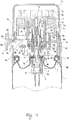
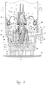
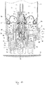
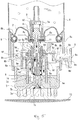
- FIGS. 1 to 5 A best mode of carrying out the invention is now described with reference to FIGS. 1 to 5 .
- a constituent element e.g., a cutout portion 3a designated by a reference numeral associated with an alphabetical suffix hereinafter indicates that this element is in principle part of a constituent element (e.g., a housing 3) designated by an alphabetical portion of the reference numeral.
- FIGS. 1 to 5 designated by A is a continuous space from an inflow valve to an outflow valve constituting a constant-volume chamber in which content to be ejected in a constant volume and liquefied gas are once stored, indicated by B is a state in which the content flows from a container body into the constant-volume chamber A (refer to FIGS. 3 and 4 ), and indicated by C is a state in which the content is ejected from the constant-volume chamber A into an external space (refer to FIG. 5 ).
- designated by 1 is the container body of an aerosol-type product accommodating the content and ejecting gas which will be described later
- designated by 2 is a mounting cap attached to an open end side of the container body 1
- designated by 3 is the housing attached to a central portion of the mounting cap 2
- designated by 3a is the cutout portion formed in part of a peripheral surface of the housing to serve as a content inflow portion during inverted constant-volume ejection
- designated by 4 is a stem of which lower portion is disposed inside the housing 3, the stem 4 being biased in an upward direction when in an upright position by elastic action of a later-described conventional stem coil spring 10 and serving as a constant-volume chamber inflow valve together with a later-described conventional stem gasket 11, designated by 4a is an inner passage, and designated by 4b is a lateral hole portion constituting one side of the constant-volume chamber inflow valve.
- the cylindrical movable member which can be moved up and down relative to the valve member 5, the movable member 6 defining the constant-volume chamber A, designated by 6a is an inner cylindrical portion with which the inverted skirt portion 5d comes into tight contact, designated by 6b is an outer cylindrical portion fitted in the later-described pressing member 7, designated by 6c are a plurality of legs fitted in the respective locking holes 5f, designated by 6d are raised portions formed on outside surfaces of the legs for preventing the legs 6c from coming off the locking holes 5f in the longitudinal direction, designated by 6e are a total of two driven parallelepipedic protrusions formed on a curved outside surface of the movable member at opposite locations separated by 180 degrees from each other along a circumferential direction, the driven parallelepipedic protrusions 6e serving to produce cam action together with a later-described pushing lever 8, designated by 6f are inverted-position lower edge portions of the driven parallelepipedic protrusions located on the side of a later-described operating surface 8a, and
- the pressing member which is fixed to the outer cylindrical portion 6b of the movable member 6, defining the constant-volume chamber A, and constitutes the constant-volume chamber outflow valve together with the valve member 5, the pressing member 7 being of a needlepoint-holder-type having channels to the external space and movable along an upward/downward direction
- designated by 7a is an annular groove 7a in which the outer cylindrical portion 6b is affixed
- designated by 7b is a passage formed between the inside and outside of the pressing member
- designated by 7c are a plurality of orifices formed on an outlet side of the passage for ejecting the content
- designated by 7d is a circular edge portion at an inlet section of the passage, the circular edge portion 7d constituting the other side of the constant-volume chamber outflow valve by going into contact with and apart from the central truncated conical portion 5a of the valve member 5, and designated by 7e are a plurality of projections (needles) which go into contact with an ejection target area like later-de
- 8 is the pushing lever which moves in a lateral direction toward a middle part of the container and thereby drives the pressing member 7 to a pushed position thereof as a result of pushing action performed by a user
- 8a is the operating surface provided on the outside of a later-described shoulder cover 9
- 8b is a generally rectangular basal portion which connects inward from the push-action operating surface
- 8c are a pair of straight arm portions individually extending inward from both widthwise ends of the basal portion
- 8d are slant surfaces formed at far end portions of the respective straight arm portions, the slant surfaces 8d serving to produce cam action by going into contact with the inverted-position lower edge portions 6f of the driven parallelepipedic protrusions 6e
- 8e is an arciform concave portion formed in an upright-position upper surface of the basal portion 8b
- designated by 8f is a raised portion formed on an upright-position upper surface on the inside of the arciform concave portion for restricting
- 9 is the shoulder cover which is fitted on an undercut part of the mounting cap 2 (i.e., an annular recessed part between an outer end portion of the mounting cap and the container body 1) and stays fixed to the container body 1 in either of constant-volume chamber inflow mode and inverted constant-volume ejection mode
- 9a is an outer cylindrical portion which is fitted on the mounting cap 2
- 9b is an annular swelling part formed on a curved inside surface of the outer cylindrical portion at a lower end thereof for fitting the outer cylindrical portion 9a on the mounting cap
- 9c is an opening formed in part of the outer cylindrical portion for passing the basal portion 8b of the pushing lever 8 and guiding the basal portion 8b to positions along the upward/downward direction and the lateral direction
- 9d is a position limiting part which is a curved inside surface portion located immediately above the opening when in the upright position for engaging with the raised portion 8f of the pushing lever 8 in a most retracted position thereof
- 9e is an inner cylindrical portion connected to the outer cylindrical
- the shelf-surface guide portion 9k having a flat platelike shape extending along the vertical direction as illustrated to guide upright-position lower surfaces of the respective straight arm portions 8c.
- the stem coil spring disposed inside the housing 3 for biasing the stem 4 in the upward direction
- designated by 11 is the stem gasket disposed between an inside surface of the mounting cap 2 at an inner end portion thereof and an upright-position upper end portion of the housing 3 in such a manner as to close off the lateral hole portion 4b of the stem 4 in stationary mode
- the stem gasket 11 constituting the other side of the constant-volume chamber inflow valve
- designated by 12 is a top cap having a detachable shape and attached to the arciform concave portion 8e of the pushing lever 8 and to the outer cylindrical portion 9a of the shoulder cover 9, and designated by 13 is the scalp which is a constant-volume ejection target area.
- elements like the housing 3, the stem 4, the valve member 5, the movable member 6, the pressing member 7, the pushing lever 8, the shoulder cover 9 and the top cap 12 are plastic members made of such materials as polypropylene, polyethylene, polyacetal, nylon or polybutylene terephthalate.
- the container body 1 and the mounting cap 2 are metallic members.
- the stem coil spring 10 is a metallic or plastic member and the stem gasket 11 is a rubber member.
- the stem 4 moves upward due to an elastic force of the stem coil spring 10 as in an ordinary aerosol-type product so that the lateral hole portion 4b of the stem is closed by the stem gasket 11. This means that the constant-volume chamber inflow valve is in a "closed" state.
- the movable member 6 and the pressing member 7 which is integrally assembled with the movable member 6 are in a state in which the circular edge portion 7d at an inlet side of the passage 7b of the pressing member 7 is in contact with the central truncated conical portion 5a of the valve member 5. This means that the constant-volume chamber outflow valve is set in an open state.
- the distance between the central truncated conical portion 5a and the circular edge portion 7d is approximately 0.1 mm only at this time.
- the constant-volume chamber inflow mode of FIG. 3 depicts a situation in which the user holding the container body 1 presses the projections 7e of the pressing member 7 against the scalp 13, causing the container body and the shoulder cover 9 assembled integrally therewith to move downward in the inverted position relative to the stem 4, the valve member 5, the movable member 6 and the pressing member 7.
- the constant-volume chamber inflow mode of FIG. 3 may be regarded as a situation where the stem 4, the valve member 5, the movable member 6 and the pressing member 7 have moved upward relative to the container body 1 in the inverted position.
- the constant-volume chamber inflow mode of FIG. 4 depicts a situation in which the user pushes the operating surface 8a of the pushing lever 8 inward in an arrow direction as illustrated and, as a consequence, the cam action produced between the slant surfaces 8d of the respective straight arm portions 8c of the pushing lever and the inverted-position lower edge portions 6f of the respective driven parallelepipedic protrusions 6e of the movable member 6 has caused the movable member and the pressing member 7 assembled integrally therewith to move upward in the inverted position.
- movements on the actuator side can be expressed as follows in terms of a relationship among relative positions referenced to the container body 1:
- the actuator side is shifted to a state in which the constant-volume chamber inflow valve is opened and the constant-volume chamber outflow valve is closed in the constant-volume chamber inflow mode of FIGS. 3 and 4 .
- the content of the container body 1 in the inverted position depicted in FIGS. 3 and 4 and ejecting liquefied gas flow into the constant-volume chamber A and stored therein through "the cutout portion 3a of the housing 3, an annular space between a curved inside surface of the housing 3 and the curved outside surface of the stem 4, the lateral hole portion 4b of the stem 4, the inner passage 4a of the stem 4, an internal space of the valve member 5 and the holes 5c of the valve member 5 in this order" as indicated by arrows B.
- Depicted in the inverted constant-volume ejection mode of FIG. 5 is a mode in which operation performed on the pressing member 7 of FIG. 3 to press the same against the scalp 13 or operation performed on the pushing lever 8 of FIG. 4 to push the same inward into the container has been terminated to eject the content of the constant-volume chamber A into the external space, that is, a state in which the constant-volume chamber inflow valve is closed and the constant-volume chamber outflow valve is opened.
- the ejection mechanism shifts to the inverted constant-volume ejection mode only when both of these operations are terminated.
- the ejection mechanism shifts to the inverted constant-volume ejection mode in the state in which the constant-volume chamber inflow valve is closed and the constant-volume chamber outflow valve is opened in the aforementioned manner, the content of the constant-volume chamber A is ejected into the external space through "a space of a gap between the central truncated conical portion 5a of the valve member 5 and the circular edge portion 7d of the pressing member 7, the passage 7b and the plurality of orifices 7c" as indicated by arrows C in FIG. 5 due to action of the liquefied gas.
- the movable member 6 and the pressing member 7 move downward relative to the valve member 5 due to an effect of the pressure of the content of the constant-volume chamber A (an effect of the pressure of the liquefied gas).
- a pressure oriented downward as illustrated acts on a ceiling portion of the pressing member defining the constant-volume chamber and the weights of the movable member 6 and the pressing member 7 act downward.
- the constant-volume chamber outflow valve is set to the "open" state by the pressure itself of the content of the constant-volume chamber without the provision of the aforementioned operating button coil spring 23 for opening the constant-volume chamber outflow valve as described above.
- the number of components of the constant-volume ejection mechanism is reduced by as much as this operating button coil spring and it becomes correspondingly easier to perform operations for setting the pressing member 7 and the pushing lever 8 to the constant-volume chamber inflow mode.
- valve member 5 and the pressing member 7 move in directions in which these members 5 and 7 are relatively separated from each other due to the effect of the pressure of the stored content, potentially creating a situation where the content is continuously ejected in an ordinary fashion.
- the aforementioned load applied by the pressure of the content of the constant-volume chamber A is set to a value of 0.3 to 1.5 kgf, for example. It is to be noted however that this value is merely exemplary and the load may be set to an arbitrary value that satisfies the aforementioned requirements (41) and (42).
- the actuator-inverted constant-volume ejection mechanism illustrated is assembled generally by the below-described procedure:
- the movable member 6, the pushing lever 8 and the shoulder cover 9 are made of plastic. Therefore, these members 6, 8, 9 individually deform in a range in which the members can elastically restore their original shapes during a fitting process mentioned in point (54) above, so that the straight arm portions 8c, the inner cylindrical portion 9e and the upright-position upper-side connecting portions 9j in which the driven parallelepipedic protrusions 6e on the movable member 6 are fitted can slide over the driven parallelepipedic protrusions 6e.
- the present invention is not limited to the illustrated actuator-inverted constant-volume ejection mechanism, but the pressing member 7 may be configured as an operating member of a tilt type and not of a longitudinally moving type.
- Aerosol-type products to which the invention is applied include products for various applications such as those for an air freshener, a detergent, a cleaning agent, an antiperspirant, a coolant, an anti-inflammatory agent, a hair styling agent, a hair treatment agent, a hair dye, a hair tonic, cosmetics, shaving foam, a food, a liquid droplet product (e.g., vitamin), a medical supply, a nonmedicinal product, paint, a horticultural agent, a pesticide (insect repellent), a cleaner, laundry starch, urethane foam, a fire extinguisher, a bonding agent and a lubricant.
- a detergent e.g., a cleaning agent
- an antiperspirant e.g., a coolant
- an anti-inflammatory agent e.g., a hair styling agent
- a hair treatment agent e.g., a hair treatment agent
- a hair dye e.g., a hair tonic
- the content to be accommodated in the container body may be of any of various forms, such as liquid, cream or gel types. Additionally, ingredients that may be mixed in the content may be products like powders, oil components, alcohols, surfactants, high molecular compounds, any of components effective for individual applications and water, for example.
- the powders that may be used are a metal salt powder, an inorganic powder, a resin powder and the like.
- the usable powder products include talc, kaolin, aluminum hydroxychloride (aluminum salt), calcium alginate, gold dust, silver dust, mica, carbonate, barium sulfate, cellulose, and a mixture thereof, for example.
- the oil components that may be used include silicone oil, palm oil, eucalyptus oil, camellia oil, olive oil, jojoba oil, paraffin oil, myristic acid, palmitic acid, stearic acid, linoleic acid and linolenic acid, for example.
- the alcohols that may be used include monohydric lower alcohols like ethanol, monohydric higher alcohols like lauryl alcohol, and polyalcohols like ethylene glycol, glycerin and 1, 3-butylene glycol, for example.
- the surfactants that may be used include an anionic surfactant like sodium lauryl sulfate, a nonionic detergent like polyoxyethyleneoleyl ether, an amphoteric surfactant like lauryl dimethyl aminoacetic acid betaine, and a cationic surfactant like alkyl trimethyl ammonium chloride, for example.
- the high molecular compounds that may be used include methyl cellulose, gelatin, starch, casein, hydroxyethyl cellulose, xanthan gum and carboxyvinyl polymer, for example.
- the components effective for individual applications include anti-inflammatory analgesics like methyl salicylate and indomethacin, sterilization chemicals like sodium benzoate and cresol, insect repellents like pyrethroid and diethyltoluamide, an antiperspirant like zinc oxide, refreshments like camphor and menthol, antiasthmatic drugs like ephedrine and adrenaline, sweeteners like sucralose and aspartame, bonding agents and paints like epoxy resin and urethane, dyes like paraphenylenediamine and aminophenol, and fire extinguishing compositions like ammonium dihydrogen phosphate and sodium/potassium bicarbonate, for example.
- analgesics like methyl salicylate and indomethacin
- sterilization chemicals like sodium benzoate and cresol
- insect repellents like pyrethroid and diethyltoluamide
- an antiperspirant like zinc oxide
- refreshments camphor and menthol
- antiasthmatic drugs like e
- a suspending agent an ultraviolet absorber, an emulsifier, a moisturizing agent, an antioxidant and a sequestering agent, for example.
- the ejecting gas that may be used include liquefied gases like liquefied petroleum gas, dimethyl ether and fluorocarbon as well as soluble compressed gas (e.g., carbon dioxide gas or nitrous oxide).
- liquefied gases like liquefied petroleum gas, dimethyl ether and fluorocarbon as well as soluble compressed gas (e.g., carbon dioxide gas or nitrous oxide).
Landscapes
- Chemical & Material Sciences (AREA)
- Dispersion Chemistry (AREA)
- Engineering & Computer Science (AREA)
- Mechanical Engineering (AREA)
- Containers And Packaging Bodies Having A Special Means To Remove Contents (AREA)
- Nozzles (AREA)
Claims (6)
- Stellgliedinvertierter Konstantvolumen-Ausstoßmechanismus, der Folgendes umfasst:einen Schaft (4), der eine Funktion eines Konstantvolumenkammer-Einströmventils ausführt, wobei der Schaft (4) durch eine elastische Kraft in einer ersten Richtung zu einer Position eines stationären Modus in einem Aerosolbehälter (1) vorgespannt ist;ein Ventilelement, das die Funktion eines Konstantvolumenkammer-Ausströmventils ausführt, wobei das Ventilelement (5) an dem Schaft (4) befestigt ist;ein Längsdruckelement (7), das an dem Ventilelement (5) in einer Weise angebracht ist, dass sich das Längsdruckelement (7) in der ersten Richtung und in einer zweiten Richtung, die der ersten Richtung entgegengesetzt ist, bewegen kann, und wobei das Längsdruckelement (7) eine Vielzahl von Vorsprüngen (7e) wie Nadeln eines Nadelspitzenhalters aufweist, die gegen einen Ausstoßzielbereich (13) gedrückt werden und einen Ausstoßdurchgang (7b) zu einem Außenraum aufweisen,dadurch gekennzeichnet, dassdas Längsdruckelement (7) zusammen mit dem Ventilelement (5) die Funktion des Konstantvolumenkammer-Ausströmventils (5a, 7d) ausführt und einen Konstantvolumenkammer-bildenden zylindrischen Abschnitt (6) aufweist; unddass der stellgliedinvertierte Konstantvolumen-Ausstoßmechanismus ferner Folgendes umfasst:ein seitliches Schiebeelement (8) zum Antreiben des Längsdruckelements (7) in der zweiten Richtung;eine Konstantvolumenkammer (A), die durch den Schaft (4) definiert wird, das Ventilelement (5) und das Längsdruckelement (7) zur Aufnahme eines Inhalts;einen Ventilwirkungserzeugungsabschnitt, der Teil des Schaftes (4) ist, der das Konstantvolumenkammer-Einströmventil (4b) bildet, das in einen offenen Zustand übergeht, bei dem der Inhalt eines Behälterkörpers (1) in die Konstantvolumenkammer (A) fließt, wobei sich der Schaft (4) in der zweiten Richtung bewegt und die elastische Kraft als Ergebnis einer Ausstoßwirkung überwältigt, die entweder auf das Längsdruckelement (7) oder das seitliche Schiebeelement (8) ausgeübt wird, und durch eine Wirkung der elastischen Kraft in einem geschlossenen Zustand gehalten wird, die den Schaft (4) in der ersten Richtung vorspannt, wenn die Ausstoßwirkung weder an dem Längsdruckelement (7) noch an dem seitlichen Schiebeelement (8) durchgeführt wird;einen Ventilwirkungserzeugungsabschnitt, der zwischen dem Ventilelement (5) und dem Längsdruckelement (7) angeordnet ist, wobei der Ventilwirkungserzeugungsabschnitt das Konstantvolumenkammer-Ausströmventil (5a, 7d) bildet, das durch eine Bewegung des Längsdruckelements (7) in der zweiten Richtung in einem geschlossenen Zustand bleibt, die durch die Ausstoßwirkung verursacht wird, die entweder auf das Längsdruckelement (7) oder das seitliche Schiebeelement (8) ausgeübt wird, und in einen offenen Zustand übergeht, in dem der Inhalt der Konstantvolumenkammer (A) durch eine Kraft in den Ausstoßdurchgang (7b) strömt, die auf das Längsdruckelement (7) in der ersten Richtung ausgeübt wird, nachdem die Ausstoßwirkung beendet worden ist.
- Stellgliedinvertierter Konstantvolumen-Ausstoßmechanismus nach Anspruch 1, wobei das Längsdruckelement (7) mindestens ein Paar von ersten Nockenwirkungs-Erzeugungsabschnitten (6e) auf einer gekrümmten Außenfläche des Konstantvolumenkammer-bildenden zylindrischen Abschnitts (6) aufweist, wobei das Paar von ersten Nockenwirkungs-Erzeugungsabschnitten (6e) so konfiguriert ist, dass es als Folge einer Bewegung des seitlichen Schiebeelements (8), die durch die Ausstoßwirkung verursacht wird, in der zweiten Richtung angetrieben wird, und wobei das seitliche Schiebeelement (8) zweite Nockenwirkungserzeugungsabschnitte aufweist, die in Form von mindestens einem Paar von Armabschnitten (8c) gebildet sind, die mit den ersten Nockenwirkungs-Erzeugungsabschnitten (6e) in Berührung kommen, wenn die Ausstoßwirkung durchgeführt wird.
- Stellgliedinvertierter Konstantvolumen-Ausstoßmechanismus nach Anspruch 1 oder 2, der ferner eine Schulterabdeckung (9) aufweist, die auch dann, wenn die Ausstoßwirkung durchgeführt wird, an dem Behälterkörper (1) befestigt bleibt, wobei die Schulterabdeckung (9) einen Führungsabschnitt (9c, 9j, 9k) zum Führen des seitlichen Schiebeelements (8) entlang einer seitlichen Richtung umfasst, wenn die Ausstoßwirkung durchgeführt wird.
- Stellgliedinvertierter Konstantvolumen-Ausstoßmechanismus nach einem der Ansprüche 1 bis 3, wobei die auf das Längsdruckelement (7) in der ersten Richtung ausgeübte Kraft durch einen Druck des Ausstoßgases erzeugt wird, das in der Konstantvolumenkammer (A) aufgenommen wird.
- Stellgliedinvertierter Konstantvolumen-Ausstoßmechanismus nach einem der Ansprüche 1 bis 4, der ferner ein Gehäuse (3) umfasst, das an dem Behälterkörper (1) befestigt ist und als stromaufwärtiger Raum des Konstantvolumenkammer-Einströmventils (4b) zur Aufnahme eines unteren Teils des Schaftes (4) und eines Elements (10) zur Erzeugung der elastischen Kraft dient, wobei das Gehäuse (3) eine Öffnung (3a) in einer Umfangsfläche aufweist, durch die der Inhalt in das Gehäuse (3) fließt, wenn der Behälter (1) in einer umgekehrten Position angeordnet ist.
- Aerosol-artiges Produkt, das den stellgliedinvertierten Konstantvolumen-Ausstoßmechanismus nach einem der Ansprüche 1 bis 5 umfasst und ein Druckmittel und einen Inhalt aufnimmt.
Applications Claiming Priority (1)
| Application Number | Priority Date | Filing Date | Title |
|---|---|---|---|
| PCT/JP2010/065546 WO2012032638A1 (ja) | 2010-09-09 | 2010-09-09 | アクチュエータ倒立定量噴射機構および、このアクチュエータ倒立定量噴射機構を備えたエアゾール式製品 |
Publications (3)
| Publication Number | Publication Date |
|---|---|
| EP2615044A1 EP2615044A1 (de) | 2013-07-17 |
| EP2615044A4 EP2615044A4 (de) | 2016-11-23 |
| EP2615044B1 true EP2615044B1 (de) | 2017-12-20 |
Family
ID=45810259
Family Applications (1)
| Application Number | Title | Priority Date | Filing Date |
|---|---|---|---|
| EP10856986.4A Not-in-force EP2615044B1 (de) | 2010-09-09 | 2010-09-09 | Betätiger für invertierten injektionsmechanismus mit konstantem volumen für aerosolartiges produkt |
Country Status (6)
| Country | Link |
|---|---|
| US (1) | US8893933B2 (de) |
| EP (1) | EP2615044B1 (de) |
| JP (1) | JP5597893B2 (de) |
| KR (1) | KR101702172B1 (de) |
| CN (1) | CN103097261B (de) |
| WO (1) | WO2012032638A1 (de) |
Families Citing this family (19)
| Publication number | Priority date | Publication date | Assignee | Title |
|---|---|---|---|---|
| US9706832B2 (en) * | 2012-08-28 | 2017-07-18 | The Procter & Gamble Company | Dispensers and applicator heads therefor |
| JP6467147B2 (ja) * | 2014-06-06 | 2019-02-06 | 株式会社ダイゾー | エアゾール製品 |
| CN104613197A (zh) * | 2015-01-26 | 2015-05-13 | 中山市美捷时包装制品有限公司 | 一种万向定量阀 |
| KR101990236B1 (ko) | 2015-04-06 | 2019-06-17 | 에스.씨. 존슨 앤 선 인코포레이티드 | 분배 시스템 |
| AU2016294516A1 (en) | 2015-07-15 | 2018-02-08 | Gary Rayner | Systems and methods for producing a foamable and/or flowable material for consumption |
| DE102015111551A1 (de) * | 2015-07-16 | 2017-01-19 | Rpc Bramlage Gmbh | Ausgabeeinrichtung für einen Fluidspender |
| JP6568805B2 (ja) * | 2016-01-20 | 2019-08-28 | 株式会社吉野工業所 | 吐出面に内容物を吐出する吐出容器 |
| JP6568806B2 (ja) * | 2016-01-20 | 2019-08-28 | 株式会社吉野工業所 | 吐出面に内容物を吐出する吐出容器 |
| EP3409618B1 (de) | 2016-01-29 | 2023-08-23 | Daizo Corporation | Ausstosselement und aerosolprodukt mit verwendung davon |
| JP2017214136A (ja) * | 2016-06-02 | 2017-12-07 | 株式会社ダイゾー | 氷結性内容物用の吐出部材 |
| JP6853925B2 (ja) * | 2018-01-29 | 2021-04-07 | 株式会社三谷バルブ | エアゾール容器の定量バルブ機構およびこの定量バルブ機構を備えたエアゾール式製品 |
| JP7280461B2 (ja) * | 2018-12-28 | 2023-05-24 | 花王株式会社 | エアゾール容器の定量噴射機構 |
| KR102723512B1 (ko) * | 2019-08-13 | 2024-10-30 | 가부시키가이샤 미타니 밸브 | 에어졸 용기의 역 정량 분사 기구 및 이 역 정량 분사 기구를 구비한 에어졸식 제품 |
| KR102105377B1 (ko) * | 2019-10-21 | 2020-04-28 | 권태웅 | 역립형 미스트 분무기 |
| US11019908B1 (en) * | 2020-04-20 | 2021-06-01 | Kevin Schmidt | Shaving brush and applicator |
| JP7763668B2 (ja) * | 2022-01-06 | 2025-11-04 | 株式会社ロキテクノ | 容器接続システムおよび流体容器 |
| JP7837749B2 (ja) * | 2022-02-28 | 2026-03-31 | 東洋エアゾール工業株式会社 | エアゾール用アクチュエータ |
| USD1056337S1 (en) | 2022-07-22 | 2024-12-31 | The Gillette Company Llc | Shaving composition applicator |
| CN119584888A (zh) | 2022-07-22 | 2025-03-07 | 吉列有限责任公司 | 个人护理产品分配系统 |
Family Cites Families (29)
| Publication number | Priority date | Publication date | Assignee | Title |
|---|---|---|---|---|
| US3093857A (en) * | 1961-08-21 | 1963-06-18 | Hersh Arthur | Aerosol container control mechanism fitted with applicator |
| US4252455A (en) * | 1979-06-11 | 1981-02-24 | Pena Abelardo De | Shaving brush attachment |
| US4636102A (en) * | 1983-10-12 | 1987-01-13 | Ekard Industries | Combination brush and applicator unit |
| CA2030297A1 (en) * | 1990-11-20 | 1992-05-21 | Telekesi Laszlo | Dispensing head and method for applying foamy product on a skin surface |
| GB9725531D0 (en) * | 1997-12-02 | 1998-02-04 | Nettlefold Jonathan | Shaving brush |
| FR2777967B1 (fr) * | 1998-04-28 | 2000-06-16 | Oreal | Organe d'activation d'une valve,valve equipee de cet organe et ensemble de distribution muni de cette valve |
| US6168335B1 (en) * | 1998-08-18 | 2001-01-02 | Arich, Inc. | Applicator and dispensing device using same |
| JP4204727B2 (ja) * | 1999-12-27 | 2009-01-07 | 東洋エアゾール工業株式会社 | エアゾール容器のバルブ開閉機構 |
| FR2805442B1 (fr) * | 2000-02-25 | 2003-02-14 | Oreal | Dispositif pour le conditionnement et l'application d'une composition capillaire |
| JP4144688B2 (ja) * | 2002-04-09 | 2008-09-03 | 株式会社三谷バルブ | 定量弁付噴射ボタン |
| JP4050094B2 (ja) * | 2002-05-28 | 2008-02-20 | 株式会社三谷バルブ | 定量バルブ機構およびエアゾール製品 |
| JP4071059B2 (ja) * | 2002-07-12 | 2008-04-02 | 株式会社三谷バルブ | エアゾール容器用の流量調整機構およびこれを備えたエアゾール式製品 |
| JP4137543B2 (ja) * | 2002-07-15 | 2008-08-20 | 株式会社三谷バルブ | 遅延噴射機構およびこれを用いたエアゾール式製品 |
| US6968849B2 (en) * | 2002-07-19 | 2005-11-29 | Revlon Consumer Products Corporation | Method, compositions, and kits for coloring hair |
| AU2003260367A1 (en) * | 2002-08-06 | 2004-02-25 | Glaxo Group Limited | A dispenser |
| JP4578185B2 (ja) * | 2003-12-12 | 2010-11-10 | 大正製薬株式会社 | エアゾール容器用の小分定量分配装置 |
| US20080017672A1 (en) * | 2004-10-07 | 2008-01-24 | Mitani Valve Co., Ltd | Flow Rate Regulator Unit For Aerosol Container, Flow Rate Regulator Mechanism For Aerosol Container And Aerosol Type Product |
| KR100586812B1 (ko) * | 2005-02-22 | 2006-06-09 | 전용복 | 피부 관리장치 |
| JP2006325981A (ja) | 2005-05-26 | 2006-12-07 | Kyowa Industrial Co Ltd | マッサージ機能を備えたエアゾール容器用ノズル |
| DE102005025593A1 (de) * | 2005-06-03 | 2006-12-07 | Wella Ag | Vorrichtung zum Aufbringen eines fließfähigen Produktes auf menschliches Kopfhaar |
| JP4747325B2 (ja) * | 2006-02-06 | 2011-08-17 | 株式会社三谷バルブ | エアゾール容器の定量噴射機構および、この定量噴射機構を備えたエアゾール式製品 |
| WO2007116457A1 (ja) * | 2006-03-30 | 2007-10-18 | Mitani Valve Co., Ltd. | 内容物放出用のポンプ機構およびこのポンプ機構を備えたポンプ式製品 |
| JP4973985B2 (ja) | 2006-05-11 | 2012-07-11 | 株式会社三谷バルブ | 定量噴射機構および、この定量噴射機構を備えたエアゾール式製品 |
| JP4737540B2 (ja) * | 2006-05-31 | 2011-08-03 | 株式会社吉野工業所 | エアゾール式塗布等容器 |
| JP4935276B2 (ja) * | 2006-09-27 | 2012-05-23 | 株式会社三谷バルブ | エアゾール容器の連続噴射機構および、この連続噴射機構を備えたエアゾール式製品 |
| GB0725217D0 (en) * | 2007-12-24 | 2008-02-06 | Reckitt Benckiser Uk Ltd | Cleaning device |
| US9427060B2 (en) * | 2010-06-25 | 2016-08-30 | Kampalook Ltd. | Device, kit and method for coloring hair |
| US8631975B2 (en) * | 2011-04-25 | 2014-01-21 | Toly Korea, Inc. | Airless pump and cosmetic container having the same |
| US9706832B2 (en) * | 2012-08-28 | 2017-07-18 | The Procter & Gamble Company | Dispensers and applicator heads therefor |
-
2010
- 2010-09-09 US US13/821,848 patent/US8893933B2/en active Active
- 2010-09-09 EP EP10856986.4A patent/EP2615044B1/de not_active Not-in-force
- 2010-09-09 KR KR1020137006539A patent/KR101702172B1/ko not_active Expired - Fee Related
- 2010-09-09 WO PCT/JP2010/065546 patent/WO2012032638A1/ja not_active Ceased
- 2010-09-09 CN CN201080069010.0A patent/CN103097261B/zh not_active Expired - Fee Related
- 2010-09-09 JP JP2010545302A patent/JP5597893B2/ja not_active Expired - Fee Related
Non-Patent Citations (1)
| Title |
|---|
| None * |
Also Published As
| Publication number | Publication date |
|---|---|
| KR101702172B1 (ko) | 2017-02-02 |
| US8893933B2 (en) | 2014-11-25 |
| JP5597893B2 (ja) | 2014-10-01 |
| EP2615044A1 (de) | 2013-07-17 |
| US20130175305A1 (en) | 2013-07-11 |
| CN103097261A (zh) | 2013-05-08 |
| WO2012032638A1 (ja) | 2012-03-15 |
| KR20130097189A (ko) | 2013-09-02 |
| JPWO2012032638A1 (ja) | 2013-12-12 |
| CN103097261B (zh) | 2014-11-19 |
| EP2615044A4 (de) | 2016-11-23 |
Similar Documents
| Publication | Publication Date | Title |
|---|---|---|
| EP2615044B1 (de) | Betätiger für invertierten injektionsmechanismus mit konstantem volumen für aerosolartiges produkt | |
| US8245887B2 (en) | Content discharge mechanism for pump-type container and pump-type product with content discharge mechanism | |
| EP2551214A1 (de) | Behälterabdeckung und aerosolprodukt mit der behälterabdeckung | |
| JP5055577B2 (ja) | 定量バルブ機構および、この定量バルブ機構を備えたエアゾール式製品 | |
| EP1958892A1 (de) | Spitzenstoppmechanismus, pumpenartiges produkt mit spitzenstoppmechanismus und aerosolprodukt mit spitzenstoppmechanismus | |
| JP2014037268A (ja) | トリガー操作式内容物放出機構ならびにこのトリガー操作式内容物放出機構を備えたエアゾール式製品およびポンプ式製品 | |
| JP5164109B2 (ja) | 定量噴射機構および、この定量噴射機構を備えたエアゾール式製品 | |
| JP5597892B2 (ja) | アクチュエータ定量噴射機構および、このアクチュエータ定量噴射機構を備えたエアゾール式製品 | |
| JP5628654B2 (ja) | 噴射口詰まり防止機構および噴射口詰まり防止機構を備えたエアゾール式製品 | |
| JP5408696B2 (ja) | シャットオフ機構,シャットオフ機構を備えたポンプ式製品およびシャットオフ機構を備えたエアゾール式製品、ならびにシャットオフ機構の組立方法 | |
| JP6099245B2 (ja) | 内容物放出口シャットオフ用のスパウトユニット、このスパウトユニットを組み込んだ内容物放出口シャットオフ機構、ならびにこの内容物放出口シャットオフ機構を用いたポンプ式製品およびエアゾール式製品 | |
| JP5991732B2 (ja) | エアゾール容器の逆定量噴射機構および、この逆定量噴射機構を備えたエアゾール式製品 | |
| JP2010215245A (ja) | シャットオフ機構,シャットオフ機構を備えたポンプ式製品および、シャットオフ機構を備えたエアゾール式製品 | |
| JP6731741B2 (ja) | 放出口近くの残留内容物押出し作用を呈する内容物放出機構ならびにこの内容物放出機構を備えたエアゾール式製品およびポンプ式製品 | |
| JP6601899B2 (ja) | 内容物流入用チューブ逆流機構およびこの内容物流入用チューブ逆流機構を備えたポンプ式製品 | |
| JP6465429B2 (ja) | 内容物放出操作ロック機構ならびに内容物放出操作ロック機構を備えたエアゾール式製品およびポンプ式製品 | |
| JP6703838B2 (ja) | 直線スライド操作式の内容物放出機構ならびにこの内容物放出機構を備えたエアゾール式製品およびポンプ式製品 | |
| JP2005306459A (ja) | ガス抜き機構およびエアゾール式製品 | |
| JP7852907B2 (ja) | 定量噴射機構および、この定量噴射機構を備えたエアゾール式製品 | |
| CN113993794A (zh) | 气雾剂容器的反向定量喷射机构和具备该反向定量喷射机构的气雾剂式产品 | |
| JP2015212170A (ja) | シャットオフ形式の内容物放出操作ロック機構ならびにシャットオフ形式の内容物放出操作ロック機構を備えたエアゾール式製品およびポンプ式製品 | |
| JP5300058B2 (ja) | シャットオフ機構ならびにこのシャットオフ機構を備えたポンプ式製品およびエアゾール式製品 | |
| JP5046327B2 (ja) | エアゾール容器のガス抜き機構および、このガス抜き機構を備えたエアゾール式製品 | |
| JP2006160300A (ja) | 内容物放出機構およびそれを備えたエアゾール式製品 | |
| JP2016016893A (ja) | エアゾール連続噴射機構およびこのエアゾール噴射操作機構を備えたエアゾール式製品 |
Legal Events
| Date | Code | Title | Description |
|---|---|---|---|
| PUAI | Public reference made under article 153(3) epc to a published international application that has entered the european phase |
Free format text: ORIGINAL CODE: 0009012 |
|
| 17P | Request for examination filed |
Effective date: 20130325 |
|
| AK | Designated contracting states |
Kind code of ref document: A1 Designated state(s): AL AT BE BG CH CY CZ DE DK EE ES FI FR GB GR HR HU IE IS IT LI LT LU LV MC MK MT NL NO PL PT RO SE SI SK SM TR |
|
| DAX | Request for extension of the european patent (deleted) | ||
| RA4 | Supplementary search report drawn up and despatched (corrected) |
Effective date: 20161026 |
|
| RIC1 | Information provided on ipc code assigned before grant |
Ipc: B65D 83/20 20060101AFI20161020BHEP Ipc: B65D 83/36 20060101ALI20161020BHEP Ipc: B65D 83/54 20060101ALI20161020BHEP Ipc: B65D 83/28 20060101ALI20161020BHEP |
|
| REG | Reference to a national code |
Ref country code: DE Ref legal event code: R079 Ref document number: 602010047580 Country of ref document: DE Free format text: PREVIOUS MAIN CLASS: B65D0083140000 Ipc: B65D0083200000 |
|
| RIC1 | Information provided on ipc code assigned before grant |
Ipc: B65D 83/36 20060101ALI20170601BHEP Ipc: B65D 83/20 20060101AFI20170601BHEP Ipc: B65D 83/54 20060101ALI20170601BHEP Ipc: B65D 83/28 20060101ALI20170601BHEP |
|
| GRAP | Despatch of communication of intention to grant a patent |
Free format text: ORIGINAL CODE: EPIDOSNIGR1 |
|
| INTG | Intention to grant announced |
Effective date: 20170712 |
|
| GRAS | Grant fee paid |
Free format text: ORIGINAL CODE: EPIDOSNIGR3 |
|
| GRAA | (expected) grant |
Free format text: ORIGINAL CODE: 0009210 |
|
| AK | Designated contracting states |
Kind code of ref document: B1 Designated state(s): AL AT BE BG CH CY CZ DE DK EE ES FI FR GB GR HR HU IE IS IT LI LT LU LV MC MK MT NL NO PL PT RO SE SI SK SM TR |
|
| REG | Reference to a national code |
Ref country code: GB Ref legal event code: FG4D |
|
| REG | Reference to a national code |
Ref country code: CH Ref legal event code: EP |
|
| REG | Reference to a national code |
Ref country code: IE Ref legal event code: FG4D |
|
| REG | Reference to a national code |
Ref country code: AT Ref legal event code: REF Ref document number: 956148 Country of ref document: AT Kind code of ref document: T Effective date: 20180115 |
|
| REG | Reference to a national code |
Ref country code: DE Ref legal event code: R096 Ref document number: 602010047580 Country of ref document: DE |
|
| REG | Reference to a national code |
Ref country code: NL Ref legal event code: MP Effective date: 20171220 |
|
| PG25 | Lapsed in a contracting state [announced via postgrant information from national office to epo] |
Ref country code: NO Free format text: LAPSE BECAUSE OF FAILURE TO SUBMIT A TRANSLATION OF THE DESCRIPTION OR TO PAY THE FEE WITHIN THE PRESCRIBED TIME-LIMIT Effective date: 20180320 Ref country code: LT Free format text: LAPSE BECAUSE OF FAILURE TO SUBMIT A TRANSLATION OF THE DESCRIPTION OR TO PAY THE FEE WITHIN THE PRESCRIBED TIME-LIMIT Effective date: 20171220 Ref country code: SE Free format text: LAPSE BECAUSE OF FAILURE TO SUBMIT A TRANSLATION OF THE DESCRIPTION OR TO PAY THE FEE WITHIN THE PRESCRIBED TIME-LIMIT Effective date: 20171220 Ref country code: FI Free format text: LAPSE BECAUSE OF FAILURE TO SUBMIT A TRANSLATION OF THE DESCRIPTION OR TO PAY THE FEE WITHIN THE PRESCRIBED TIME-LIMIT Effective date: 20171220 |
|
| REG | Reference to a national code |
Ref country code: LT Ref legal event code: MG4D |
|
| REG | Reference to a national code |
Ref country code: AT Ref legal event code: MK05 Ref document number: 956148 Country of ref document: AT Kind code of ref document: T Effective date: 20171220 |
|
| PG25 | Lapsed in a contracting state [announced via postgrant information from national office to epo] |
Ref country code: HR Free format text: LAPSE BECAUSE OF FAILURE TO SUBMIT A TRANSLATION OF THE DESCRIPTION OR TO PAY THE FEE WITHIN THE PRESCRIBED TIME-LIMIT Effective date: 20171220 Ref country code: LV Free format text: LAPSE BECAUSE OF FAILURE TO SUBMIT A TRANSLATION OF THE DESCRIPTION OR TO PAY THE FEE WITHIN THE PRESCRIBED TIME-LIMIT Effective date: 20171220 Ref country code: GR Free format text: LAPSE BECAUSE OF FAILURE TO SUBMIT A TRANSLATION OF THE DESCRIPTION OR TO PAY THE FEE WITHIN THE PRESCRIBED TIME-LIMIT Effective date: 20180321 Ref country code: BG Free format text: LAPSE BECAUSE OF FAILURE TO SUBMIT A TRANSLATION OF THE DESCRIPTION OR TO PAY THE FEE WITHIN THE PRESCRIBED TIME-LIMIT Effective date: 20180320 |
|
| PG25 | Lapsed in a contracting state [announced via postgrant information from national office to epo] |
Ref country code: NL Free format text: LAPSE BECAUSE OF FAILURE TO SUBMIT A TRANSLATION OF THE DESCRIPTION OR TO PAY THE FEE WITHIN THE PRESCRIBED TIME-LIMIT Effective date: 20171220 |
|
| PG25 | Lapsed in a contracting state [announced via postgrant information from national office to epo] |
Ref country code: CY Free format text: LAPSE BECAUSE OF FAILURE TO SUBMIT A TRANSLATION OF THE DESCRIPTION OR TO PAY THE FEE WITHIN THE PRESCRIBED TIME-LIMIT Effective date: 20171220 Ref country code: EE Free format text: LAPSE BECAUSE OF FAILURE TO SUBMIT A TRANSLATION OF THE DESCRIPTION OR TO PAY THE FEE WITHIN THE PRESCRIBED TIME-LIMIT Effective date: 20171220 Ref country code: CZ Free format text: LAPSE BECAUSE OF FAILURE TO SUBMIT A TRANSLATION OF THE DESCRIPTION OR TO PAY THE FEE WITHIN THE PRESCRIBED TIME-LIMIT Effective date: 20171220 Ref country code: ES Free format text: LAPSE BECAUSE OF FAILURE TO SUBMIT A TRANSLATION OF THE DESCRIPTION OR TO PAY THE FEE WITHIN THE PRESCRIBED TIME-LIMIT Effective date: 20171220 Ref country code: SK Free format text: LAPSE BECAUSE OF FAILURE TO SUBMIT A TRANSLATION OF THE DESCRIPTION OR TO PAY THE FEE WITHIN THE PRESCRIBED TIME-LIMIT Effective date: 20171220 |
|
| PG25 | Lapsed in a contracting state [announced via postgrant information from national office to epo] |
Ref country code: AT Free format text: LAPSE BECAUSE OF FAILURE TO SUBMIT A TRANSLATION OF THE DESCRIPTION OR TO PAY THE FEE WITHIN THE PRESCRIBED TIME-LIMIT Effective date: 20171220 Ref country code: PL Free format text: LAPSE BECAUSE OF FAILURE TO SUBMIT A TRANSLATION OF THE DESCRIPTION OR TO PAY THE FEE WITHIN THE PRESCRIBED TIME-LIMIT Effective date: 20171220 Ref country code: IS Free format text: LAPSE BECAUSE OF FAILURE TO SUBMIT A TRANSLATION OF THE DESCRIPTION OR TO PAY THE FEE WITHIN THE PRESCRIBED TIME-LIMIT Effective date: 20180420 Ref country code: SM Free format text: LAPSE BECAUSE OF FAILURE TO SUBMIT A TRANSLATION OF THE DESCRIPTION OR TO PAY THE FEE WITHIN THE PRESCRIBED TIME-LIMIT Effective date: 20171220 Ref country code: IT Free format text: LAPSE BECAUSE OF FAILURE TO SUBMIT A TRANSLATION OF THE DESCRIPTION OR TO PAY THE FEE WITHIN THE PRESCRIBED TIME-LIMIT Effective date: 20171220 Ref country code: RO Free format text: LAPSE BECAUSE OF FAILURE TO SUBMIT A TRANSLATION OF THE DESCRIPTION OR TO PAY THE FEE WITHIN THE PRESCRIBED TIME-LIMIT Effective date: 20171220 |
|
| REG | Reference to a national code |
Ref country code: DE Ref legal event code: R097 Ref document number: 602010047580 Country of ref document: DE |
|
| REG | Reference to a national code |
Ref country code: FR Ref legal event code: PLFP Year of fee payment: 9 |
|
| PLBE | No opposition filed within time limit |
Free format text: ORIGINAL CODE: 0009261 |
|
| STAA | Information on the status of an ep patent application or granted ep patent |
Free format text: STATUS: NO OPPOSITION FILED WITHIN TIME LIMIT |
|
| 26N | No opposition filed |
Effective date: 20180921 |
|
| PG25 | Lapsed in a contracting state [announced via postgrant information from national office to epo] |
Ref country code: DK Free format text: LAPSE BECAUSE OF FAILURE TO SUBMIT A TRANSLATION OF THE DESCRIPTION OR TO PAY THE FEE WITHIN THE PRESCRIBED TIME-LIMIT Effective date: 20171220 |
|
| PG25 | Lapsed in a contracting state [announced via postgrant information from national office to epo] |
Ref country code: SI Free format text: LAPSE BECAUSE OF FAILURE TO SUBMIT A TRANSLATION OF THE DESCRIPTION OR TO PAY THE FEE WITHIN THE PRESCRIBED TIME-LIMIT Effective date: 20171220 |
|
| PG25 | Lapsed in a contracting state [announced via postgrant information from national office to epo] |
Ref country code: MC Free format text: LAPSE BECAUSE OF FAILURE TO SUBMIT A TRANSLATION OF THE DESCRIPTION OR TO PAY THE FEE WITHIN THE PRESCRIBED TIME-LIMIT Effective date: 20171220 |
|
| REG | Reference to a national code |
Ref country code: CH Ref legal event code: PL |
|
| REG | Reference to a national code |
Ref country code: BE Ref legal event code: MM Effective date: 20180930 |
|
| REG | Reference to a national code |
Ref country code: IE Ref legal event code: MM4A |
|
| PG25 | Lapsed in a contracting state [announced via postgrant information from national office to epo] |
Ref country code: LU Free format text: LAPSE BECAUSE OF NON-PAYMENT OF DUE FEES Effective date: 20180909 |
|
| PG25 | Lapsed in a contracting state [announced via postgrant information from national office to epo] |
Ref country code: IE Free format text: LAPSE BECAUSE OF NON-PAYMENT OF DUE FEES Effective date: 20180909 |
|
| PG25 | Lapsed in a contracting state [announced via postgrant information from national office to epo] |
Ref country code: BE Free format text: LAPSE BECAUSE OF NON-PAYMENT OF DUE FEES Effective date: 20180930 Ref country code: CH Free format text: LAPSE BECAUSE OF NON-PAYMENT OF DUE FEES Effective date: 20180930 Ref country code: LI Free format text: LAPSE BECAUSE OF NON-PAYMENT OF DUE FEES Effective date: 20180930 |
|
| PG25 | Lapsed in a contracting state [announced via postgrant information from national office to epo] |
Ref country code: MT Free format text: LAPSE BECAUSE OF NON-PAYMENT OF DUE FEES Effective date: 20180909 |
|
| PG25 | Lapsed in a contracting state [announced via postgrant information from national office to epo] |
Ref country code: TR Free format text: LAPSE BECAUSE OF FAILURE TO SUBMIT A TRANSLATION OF THE DESCRIPTION OR TO PAY THE FEE WITHIN THE PRESCRIBED TIME-LIMIT Effective date: 20171220 |
|
| PG25 | Lapsed in a contracting state [announced via postgrant information from national office to epo] |
Ref country code: HU Free format text: LAPSE BECAUSE OF FAILURE TO SUBMIT A TRANSLATION OF THE DESCRIPTION OR TO PAY THE FEE WITHIN THE PRESCRIBED TIME-LIMIT; INVALID AB INITIO Effective date: 20100909 Ref country code: PT Free format text: LAPSE BECAUSE OF FAILURE TO SUBMIT A TRANSLATION OF THE DESCRIPTION OR TO PAY THE FEE WITHIN THE PRESCRIBED TIME-LIMIT Effective date: 20171220 |
|
| PG25 | Lapsed in a contracting state [announced via postgrant information from national office to epo] |
Ref country code: MK Free format text: LAPSE BECAUSE OF NON-PAYMENT OF DUE FEES Effective date: 20171220 |
|
| PG25 | Lapsed in a contracting state [announced via postgrant information from national office to epo] |
Ref country code: AL Free format text: LAPSE BECAUSE OF FAILURE TO SUBMIT A TRANSLATION OF THE DESCRIPTION OR TO PAY THE FEE WITHIN THE PRESCRIBED TIME-LIMIT Effective date: 20171220 |
|
| PGFP | Annual fee paid to national office [announced via postgrant information from national office to epo] |
Ref country code: FR Payment date: 20210921 Year of fee payment: 12 |
|
| PGFP | Annual fee paid to national office [announced via postgrant information from national office to epo] |
Ref country code: GB Payment date: 20210920 Year of fee payment: 12 Ref country code: DE Payment date: 20210920 Year of fee payment: 12 |
|
| REG | Reference to a national code |
Ref country code: DE Ref legal event code: R119 Ref document number: 602010047580 Country of ref document: DE |
|
| GBPC | Gb: european patent ceased through non-payment of renewal fee |
Effective date: 20220909 |
|
| PG25 | Lapsed in a contracting state [announced via postgrant information from national office to epo] |
Ref country code: FR Free format text: LAPSE BECAUSE OF NON-PAYMENT OF DUE FEES Effective date: 20220930 Ref country code: DE Free format text: LAPSE BECAUSE OF NON-PAYMENT OF DUE FEES Effective date: 20230401 |
|
| PG25 | Lapsed in a contracting state [announced via postgrant information from national office to epo] |
Ref country code: GB Free format text: LAPSE BECAUSE OF NON-PAYMENT OF DUE FEES Effective date: 20220909 |