EP2617337A2 - Dispositif de nettoyage pour vitres - Google Patents
Dispositif de nettoyage pour vitres Download PDFInfo
- Publication number
- EP2617337A2 EP2617337A2 EP11825104.0A EP11825104A EP2617337A2 EP 2617337 A2 EP2617337 A2 EP 2617337A2 EP 11825104 A EP11825104 A EP 11825104A EP 2617337 A2 EP2617337 A2 EP 2617337A2
- Authority
- EP
- European Patent Office
- Prior art keywords
- clinging
- unit
- units
- transverse
- existing
- Prior art date
- Legal status (The legal status is an assumption and is not a legal conclusion. Google has not performed a legal analysis and makes no representation as to the accuracy of the status listed.)
- Granted
Links
- 238000004140 cleaning Methods 0.000 title claims abstract description 41
- 239000005357 flat glass Substances 0.000 title claims description 28
- 239000011521 glass Substances 0.000 claims abstract description 92
- 230000008602 contraction Effects 0.000 claims abstract description 59
- 238000007789 sealing Methods 0.000 claims abstract description 12
- 238000000034 method Methods 0.000 description 11
- 230000008878 coupling Effects 0.000 description 7
- 238000010168 coupling process Methods 0.000 description 7
- 238000005859 coupling reaction Methods 0.000 description 7
- XLYOFNOQVPJJNP-UHFFFAOYSA-N water Substances O XLYOFNOQVPJJNP-UHFFFAOYSA-N 0.000 description 3
- 230000000694 effects Effects 0.000 description 2
- 239000002184 metal Substances 0.000 description 2
- 238000005507 spraying Methods 0.000 description 2
- 238000012986 modification Methods 0.000 description 1
- 230000004048 modification Effects 0.000 description 1
- 229920002635 polyurethane Polymers 0.000 description 1
- 239000004814 polyurethane Substances 0.000 description 1
- 239000000758 substrate Substances 0.000 description 1
- 229920003051 synthetic elastomer Polymers 0.000 description 1
- 239000005061 synthetic rubber Substances 0.000 description 1
Images






Classifications
-
- B—PERFORMING OPERATIONS; TRANSPORTING
- B25—HAND TOOLS; PORTABLE POWER-DRIVEN TOOLS; MANIPULATORS
- B25J—MANIPULATORS; CHAMBERS PROVIDED WITH MANIPULATION DEVICES
- B25J5/00—Manipulators mounted on wheels or on carriages
-
- A—HUMAN NECESSITIES
- A47—FURNITURE; DOMESTIC ARTICLES OR APPLIANCES; COFFEE MILLS; SPICE MILLS; SUCTION CLEANERS IN GENERAL
- A47L—DOMESTIC WASHING OR CLEANING; SUCTION CLEANERS IN GENERAL
- A47L1/00—Cleaning windows
- A47L1/02—Power-driven machines or devices
-
- A—HUMAN NECESSITIES
- A47—FURNITURE; DOMESTIC ARTICLES OR APPLIANCES; COFFEE MILLS; SPICE MILLS; SUCTION CLEANERS IN GENERAL
- A47L—DOMESTIC WASHING OR CLEANING; SUCTION CLEANERS IN GENERAL
- A47L3/00—Safety devices for use in window-cleaning
- A47L3/02—Cages; Platforms
-
- B—PERFORMING OPERATIONS; TRANSPORTING
- B62—LAND VEHICLES FOR TRAVELLING OTHERWISE THAN ON RAILS
- B62D—MOTOR VEHICLES; TRAILERS
- B62D57/00—Vehicles characterised by having other propulsion or other ground- engaging means than wheels or endless track, alone or in addition to wheels or endless track
- B62D57/02—Vehicles characterised by having other propulsion or other ground- engaging means than wheels or endless track, alone or in addition to wheels or endless track with ground-engaging propulsion means, e.g. walking members
- B62D57/024—Vehicles characterised by having other propulsion or other ground- engaging means than wheels or endless track, alone or in addition to wheels or endless track with ground-engaging propulsion means, e.g. walking members specially adapted for moving on inclined or vertical surfaces
-
- B—PERFORMING OPERATIONS; TRANSPORTING
- B62—LAND VEHICLES FOR TRAVELLING OTHERWISE THAN ON RAILS
- B62D—MOTOR VEHICLES; TRAILERS
- B62D63/00—Motor vehicles or trailers not otherwise provided for
- B62D63/02—Motor vehicles
- B62D63/04—Component parts or accessories
-
- Y—GENERAL TAGGING OF NEW TECHNOLOGICAL DEVELOPMENTS; GENERAL TAGGING OF CROSS-SECTIONAL TECHNOLOGIES SPANNING OVER SEVERAL SECTIONS OF THE IPC; TECHNICAL SUBJECTS COVERED BY FORMER USPC CROSS-REFERENCE ART COLLECTIONS [XRACs] AND DIGESTS
- Y10—TECHNICAL SUBJECTS COVERED BY FORMER USPC
- Y10S—TECHNICAL SUBJECTS COVERED BY FORMER USPC CROSS-REFERENCE ART COLLECTIONS [XRACs] AND DIGESTS
- Y10S901/00—Robots
- Y10S901/01—Mobile robot
Definitions
- the present invention relates to a device which performs cleaning operation while being held by vacuum on a wall surface, a window surface, or the like of glass of a building, and being moved along the surface.
- Japanese Laid-Open Patent Publication No. 5-42063 proposes a device which clings to a surface and can be moved along the surface including: four sets of vertical expansion and contraction means; one set of width direction expansion and contraction means disposed for each one of the four sets of vertical expansion and contraction means; clinging units of which is disposed for each one of the width direction expansion and contraction means; and first putting forward/backward means interposed between the clinging unit and the width direction expansion and contraction means, the device being characterized in that each of the clinging units is selectively set at least in the following three states: (1) a clinging and movable state in which the device can be moved along the surface and in close contact with the surface; (2) a clinging and locked state in which the device clings to the surface in a locked manner; and (3) a non-clinging and movable state in which the device is separated from the surface and can be moved along the surface.
- Japanese Laid-Open Patent Publication No. 5-42063 proposes a device which clings to a surface and can be moved along the surface in which, in the case where a protruding bar such as a window glass frame exists on the surface, and when the protruding bar extends in the horizontal direction and the vertical direction and has a number of crossing portions, the device can be moved by stepping over the protruding bar in either of the horizontal direction or the vertical direction.
- the cleaning direction is supposed to be only the horizontal direction. The cleaning in the vertical direction is not supposed.
- the device when the device is moved by stepping over the window glass frame extending in the horizontal direction, two of the four clinging units are separated from the window glass, i.e., only the half of the clinging units included in the device is held by vacuum on the window glass, so that the device has insufficient stability in vacuum holding.
- the device on the surface of a window glass which forms an angle of 90 degrees or less with the ground, i.e., on the surface of a window glass in a so-called over-hanging condition, the device involves a problem that it cannot be moved by stepping over the window glass frame extending in the horizontal direction.
- the present invention has been conducted in view of the above-described prior art, and provides "a cleaning device for a window glass or the like" with superior stability in vacuum holding, which can move on the surface of a window glass or the like and clean the surface in either of the transverse direction or the longitudinal direction, and in which six of nine clinging units included in the device of the present invention are always held by vacuum on the window glass in the case where the device moves by stepping over the window glass frame, i.e. , two thirds of the clinging units included in the device are held by vacuum on the window glass.
- each of the clinging units includes height direction expansion and contraction means for putting the clinging unit in and out in a direction intersecting with a surface, the clinging units adjacent to each other are coupled by transverse expansion and contraction means via the height direction expansion and contraction means, when the three clinging units coupled by the transverse expansion and contraction means via the height direction expansion and contraction means are referred to a row clinging unit group, three row clinging unit groups are arranged in the longitudinal direction, the row clinging unit groups adjacent to each other are coupled by lengthwise expansion and contraction means via the height direction expansion and contraction means, each of the clinging units can be selectively set in either one of the following three states:
- each of the clinging units includes:
- the cleaning device for a window glass or the like of the present invention can attain such effects that the device can move on the surface of a window glass or the like and clean the surface in either of the transverse direction or the longitudinal direction, and that, when the device moves by stepping over the window glass frame, six of nine clinging units included in the device of the present invention are always held by vacuum on the window glass, i.e. , two thirds of the clinging units included in the device are held by vacuum, so that the device has superior stability in vacuum holding.
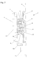
- Fig. 1 shows an embodiment in which the device of the present invention held by vacuum on the glass window surface is viewed from the front thereof.
- the up/down directions correspond to the actual up/down directions.
- the right/left directions correspond to the actual right/left directions.
- a direction getting closer to the glass window surface is referred to as a forward direction
- a direction getting away from the glass window surface is referred to as a backward direction.
- each of the clinging units 4 includes clinging unit putting forward/backward means 80, constituted by pneumatic cylinders, for putting in and out the clinging unit 4 in a direction intersecting with a glass window surface 32, the clinging units adjacent to each other are coupled by transverse expansion and contraction means 62 constituted by a pneumatic cylinder via the clinging unit putting forward/backward means 80, when the three clinging units 4 coupled by the transverse expansion and contraction means 62 via the clinging unit putting forward/backward means 80 are referred to as a row clinging unit group, three row clinging unit groups are arranged lengthwise, and the row clinging unit groups adjacent to each other are coupled by lengthwise expansion and contraction means 68 by a pneumatic cylinder via the clinging unit putting forward/backward means 80.
- each of the nine clinging units 4 will be described below in detail.
- respective one clinging unit frame member 16 is fixed.
- the clinging unit frame member 16 has a box-like shape which opens in a direction opposed to the glass window surface 32.
- a rectangular and annular vacuum sealing member 26 formed of a flexible member such as polyurethane is fixed. A free end portion of the vacuum sealing member 26 moves in the condition where it is in contact with the glass window surface 32, thereby cleaning the glass window surface 32.
- Each of the clinging units 4 includes a transverse running wheel unit 48 which enables a transverse running wheel 481 having a shaft extending in a direction parallel to the glass window surface 32 and in the longitudinal direction to protrude toward the glass window surface 32 and to move in the transverse direction, and enables the wheel to be retracted from the glass window surface 32 and to be locked by transverse running wheel unit putting forward/backward means 46 constituted by a pneumatic cylinder, and a lengthwise running wheel unit 88 which enables a lengthwise running wheel 881 having a shaft extending in a direction parallel to the glass window surface 32 and in the transverse direction to protrude toward the glass window surface 32 and to move in the longitudinal direction, and enables the wheel to be retracted from the glass window surface 32 and to be locked by lengthwise running wheel
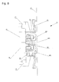
- the transverse running wheel unit 48 and the lengthwise running wheel unit 88 constitute moving means and locking means. Respective cylinder cases of the transverse running wheel unit putting forward/backward means 46 and the lengthwise running wheel unit putting forward/backward means 86 are fixed to the clinging unit frame member 16. To an end of a piston rod of the transverse running wheel unit putting forward/backward means 46, as shown in Fig. 7 , Fig. 8 , and Fig. 10 , three transverse running wheels 481 are rotatably attached with bolts by means of an inverted T shape metal attachment which is fixed to the end of the piston rod with a bolt. To an end of a piston rod of the lengthwise running wheel unit putting forward/backward means 86, as shown in Fig.
- four lengthwise running wheels 881 are rotatably attached with bolts by means of an inverted U shape metal attachment which is fixed to the end of the piston rod with a bolt.
- a locking member 38 of synthetic rubber is fixed on the inside of the clinging unit frame member 16.
- each of the pneumatic cylinders is a pneumatic cylinder which is rectangular in section, so that the piston rod of the respective pneumatic cylinder will not rotate.
- an end of each of piston rods of the pneumatic cylinders constituting the two sets of transverse expansion and contraction means 68 is fixed to the side face of a respective cylinder case of the two pneumatic cylinders constituting the clinging unit putting forward/backward means 80 existing in the center portion of the row clinging unit group via a C-shaped frame 81, and a side face of each of the cylinder cases of the pneumatic cylinders constituting the two sets of transverse expansion and contraction means 68 is fixed to a side face of each of cylinder cases of the two pneumatic cylinders constituting the two sets of clinging unit putting forward/backward means 80 existing in the side portions of the row clinging unit group via the C-shaped frame 81.
- each of piston rods of the pneumatic cylinders constituting the two sets of longitudinal expansion and contraction means 68 is fixed to the side face of a cylinder case of respective two pneumatic cylinders constituting the clinging unit putting forward/backward means 80 existing in the center portion of the center one of the row clinging unit groups via a box-shaped frame 82, and a side face of each of the cylinder case of the pneumatic cylinders constituting the two sets of longitudinal expansion and contraction means 68 is fixed to a side face of each of the cylinder cases of the two pneumatic cylinders constituting the clinging unit putting forward/backward means 80 existing in the center portion of the two row clinging unit groups existing in the end portions via the C-shaped frame 81.
- Fig. 1 to Fig. 16 show the conditions where the device in the embodiment of the present invention is held by vacuum on the glass window surface 32.
- Fig. 1 to Fig. 10 show the conditions where the piston rods of all of the pneumatic cylinders of the six sets of transverse expansion and contraction means 68 and the pneumatic cylinders of the two sets of lengthwise expansion and contraction means 68 are contracted.
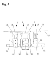
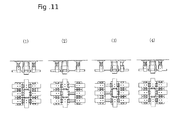
- FIG. 4 , and Fig. 11 show the condition where the piston rods of all of the pneumatic cylinders of the nine pairs of eighteen clinging unit putting forward/backward means 80 are expanded.
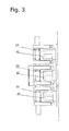
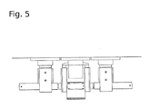
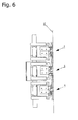
- Fig. 3 and Fig. 5 to Fig. 8 show the condition where the piston rods of all of the pneumatic cylinders of the nine pairs of eighteen clinging unit putting forward/backward means 80 are contracted.
- FIG. 8 show the condition where the transverse running wheels 481 and the lengthwise running wheels 881 in the uppermost row clinging unit group and the center row clinging unit group among the three row clinging unit groups are both in the locked state, and in the lowermost row clinging unit group, the transverse running wheels 481 are in the locked state, and the lengthwise running wheels 881 are in the rotating state.
- Fig. 6 among the two sets of lengthwise expansion and contraction means 68, when the lower lengthwise expansion and contraction means 68 is expanded, the friction force between the glass window surface 32 and the uppermost row clinging unit group and the center row clinging unit group is large, and the friction force between the glass window surface 32 and the lowermost row clinging unit group is small. As a result, the lowermost row clinging unit group is moved downwards while being held by vacuum on the glass window surface 32, thereby simultaneously performing the cleaning operation for the glass window surface 32.
- Fig. 11 shows the procedure in which the device in the embodiment of the present invention is held by vacuum on the glass window surface 32, and moved along the glass window surface 32 from the left to the right, thereby performing the cleaning for the glass window surface 32.
- (1) to (4) are four sets of top views and plan views showing four situations of the device in the embodiment of the present invention. The four sets of top views and plan views are arranged from the left to the right in the order of time series.
- Fig. 11 shows the procedure in which the device in the embodiment of the present invention is held by vacuum on the glass window surface 32, and moved along the glass window surface 32 from the left to the right, thereby performing the cleaning for the glass window surface 32.
- (1) to (4) are four sets of top views and plan views showing four situations of the device in the embodiment of the present invention. The four sets of top views and plan views are arranged from the left to the right in the order of time series.
- FIG. 11 (1) to (4) show the condition where all of the nine clinging units 4 of the device in the embodiment of the present invention are held by vacuum on the glass window surface 32, and all of the pneumatic cylinders of the nine pairs of eighteen clinging unit putting forward/backward means 80 are expanded.
- Fig. 11 (1) shows the condition where the piston rods of all of the pneumatic cylinders of the six sets of transverse expansion and contraction means 68 and the pneumatic cylinders of the two sets of lengthwise expansion and contraction means 68 are contracted, and all of the transverse running wheels 481 and the lengthwise running wheels 881 are both in the locked state in the nine clinging units 4.
- Fig. 11 (1) shows the condition where the piston rods of all of the pneumatic cylinders of the six sets of transverse expansion and contraction means 68 and the pneumatic cylinders of the two sets of lengthwise expansion and contraction means 68 are contracted, and all of the transverse running wheels 481 and the lengthwise running wheels 881 are both in the locked state in the
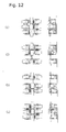
- Fig. 12 shows the procedure in which the device in the embodiment of the present invention is held by vacuum on the glass window surface 32, and moved along the glass window surface 32 from the top to the bottom, thereby performing the cleaning for the glass window surface 32.
- (1) to (4) are four sets of right side views and plan views showing four situations of the device in the embodiment of the present invention. The four sets of right side views and plan views are arranged from the top to the bottom in the order of time series.
- FIG. 12 (1) to (4) show the condition where all of the nine clinging units 4 of the device in the embodiment of the present invention are held by vacuum on the glass window surface 32, and all of the pneumatic cylinders of the nine pairs of eighteen clinging unit putting forward/backward means 80 are expanded.
- Fig. 12 (1) shows the condition where the piston rods of all of the pneumatic cylinders of the six sets of transverse expansion and contraction means 68 and the pneumatic cylinders of the two sets of lengthwise expansion and contraction means 68 are contracted, and all of the transverse running wheels 481 and the lengthwise running wheels 881 are both in the locked state in the nine clinging units 4.
- Fig. 12 (1) shows the condition where the piston rods of all of the pneumatic cylinders of the six sets of transverse expansion and contraction means 68 and the pneumatic cylinders of the two sets of lengthwise expansion and contraction means 68 are contracted, and all of the transverse running wheels 481 and the lengthwise running wheels 881 are both in the locked state in the
- Fig. 13 to Fig. 16 show the procedure in which the device in the embodiment of the present invention is held by vacuum on the glass window surface 32, moved along the glass window surface 32 from the top to the bottom, and moved by stepping over the window frame 321, thereby performing the cleaning for the glass window surface 32.
- (1) to (19) are nineteen sets of right side views and plan views showing nineteen situations of the device in the embodiment of the present invention. The nineteen sets of right side views and plan views are arranged from the top to the bottom in the order of time series.
- FIG. 13 (1) to (2) show the condition where all of the nine clinging units 4 of the device in the embodiment of the present invention are held by vacuum on the glass window surface 32, and all of the pneumatic cylinders of the nine pairs of eighteen clinging unit putting forward/backward means 80 are expanded.
- Fig. 13 (1) shows the condition where the piston rods of all of the pneumatic cylinders of the six sets of transverse expansion and contraction means 68 and the pneumatic cylinders of the two sets of lengthwise expansion and contraction means 68 are contracted, and all of the transverse running wheels 481 and the lengthwise running wheels 881 are both in the locked state in the nine clinging units 4.
- Fig. 13 (2) shows the condition where in the three clinging units 4 existing in the transverse direction in the upper end and the three clinging units 4 existing in the transverse direction in the center, the transverse running wheels 481 and the lengthwise running wheels 881 are both in the locked state; and in the three clinging units 4 existing in the transverse direction in the lower end, the transverse running wheels 481 are in the locked state and the lengthwise running wheels 881 are in the rotating state.
- the pneumatic cylinders of the lengthwise expansion and contraction means 68 on the lower side are expanded, so that the three clinging units 4 existing in the transverse direction in the lower end are moved from the top to the bottom.
- Fig. 13 (3) shows the condition where the three clinging units 4 existing in the transverse direction in the upper end and the three clinging units 4 existing in the transverse direction in the center are held by vacuum on the glass window surface 32 ; in the three clinging units 4 existing in the transverse direction in the upper end and the three clinging units 4 existing in the transverse direction in the center, the transverse running wheels 481 and the lengthwise running wheels 881 are both in the locked state; in the three clinging units 4 existing in the transverse direction in the upper end and the three clinging units 4 existing in the transverse direction in the center, the pneumatic cylinders of the clinging unit putting forward/backward means 80 are expanded; in the three clinging units 4 existing in the transverse direction in the lower end, the transverse running wheels 481 and the lengthwise running wheels 881 are both in the locked state; the three clinging units 4 existing in the transverse direction in the lower end is released from the coupling to the vacuum generating means (
- (4) shows the condition where the three clinging units 4 existing in the transverse direction in the upper end and the three clinging units 4 existing in the transverse direction in the center are held by vacuum on the glass window surface 32 ; in the three clinging units 4 existing in the transverse direction in the upper end, the transverse running wheels 481 and the lengthwise running wheels 881 are both in the locked state; in the three clinging units 4 existing in the transverse direction in the center, the transverse running wheels 481 are in the locked state and the lengthwise running wheels 881 are in the rotating state; in the three clinging units 4 existing in the transverse direction in the upper end and the three clinging units 4 existing in the transverse direction in the center, the pneumatic cylinders of the clinging unit putting forward/backward means 80 are expanded; in the three clinging units 4 existing in the transverse direction in the lower end, the transverse running wheels 481 and the lengthwise running wheels 881 are both in the locked state; the three clinging units 4 existing
- (5) shows the condition where the three clinging units 4 existing in the transverse direction in the upper end and the three clinging units 4 existing in the transverse direction in the center are held by vacuum on the glass window surface 32 ; in the three clinging units 4 existing in the transverse direction in the upper end, the transverse running wheels 481 are in the locked state and the lengthwise running wheels 881 are in the rotating state; in the three clinging units 4 existing in the transverse direction in the center, the transverse running wheels 481 and the lengthwise running wheels 881 are both in the locked state; in the three clinging units 4 existing in the transverse direction in the upper end and the three clinging units 4 existing in the transverse direction in the center, the pneumatic cylinders of the clinging unit putting forward/backward means 80 are expanded; in the three clinging units 4 existing in the transverse direction in the lower end, the transverse running wheels 481 and the lengthwise running wheels 881 are both in the locked state; the three clinging units 4 existing
- (6) shows the condition where the three clinging units 4 existing in the transverse direction in the upper end and the three clinging units 4 existing in the transverse direction in the center are held by vacuum on the glass window surface 32 ; in the three clinging units 4 existing in the transverse direction in the upper end, the transverse running wheels 481 and the lengthwise running wheels 881 are both in the locked state; in the three clinging units 4 existing in the transverse direction in the center, the transverse running wheels 481 are in the locked state and the lengthwise running wheels 881 are in the rotating state; in the three clinging units 4 existing in the transverse direction in the upper end and the three clinging units 4 existing in the transverse direction in the center, the pneumatic cylinders of the clinging unit putting forward/backward means 80 are expanded; in the three clinging units 4 existing in the transverse direction in the lower end, the transverse running wheels 481 and the lengthwise running wheels 881 are both in the locked state; the three clinging units 4 existing
- (7) shows the condition where the three clinging units 4 existing in the transverse direction in the upper end and the three clinging units 4 existing in the transverse direction in the center are held by vacuum on the glass window surface 32 ; in the three clinging units 4 existing in the transverse direction in the upper end, the transverse running wheels 481 are in the locked state and the lengthwise running wheels 881 are in the rotating state; in the three clinging units 4 existing in the transverse direction in the center, the transverse running wheels 481 and the lengthwise running wheels 881 are both in the locked state; in the three clinging units 4 existing in the transverse direction in the upper end and the three clinging units 4 existing in the transverse direction in the center, the pneumatic cylinders of the clinging unit putting forward/backward means 80 are expanded; in the three clinging units 4 existing in the transverse direction in the lower end, the transverse running wheels 481 and the lengthwise running wheels 881 are both in the locked state; the three clinging units 4 existing
- (8) shows the condition where the three clinging units 4 existing in the transverse direction in the upper end and the three clinging units 4 existing in the transverse direction in the center are held by vacuum on the glass window surface 32 ; in the three clinging units 4 existing in the transverse direction in the upper end, the transverse running wheels 481 and the lengthwise running wheels 881 are both in the locked state; in the three clinging units 4 existing in the transverse direction in the center, the transverse running wheels 481 are in the locked state and the lengthwise running wheels 881 are in the rotating state; in the three clinging units 4 existing in the transverse direction in the upper end and the three clinging units 4 existing in the transverse direction in the center, the pneumatic cylinders of the clinging unit putting forward/backward means 80 are expanded; in the three clinging units 4 existing in the transverse direction in the lower end, the transverse running wheels 481 and the lengthwise running wheels 881 are both in the locked state; the three clinging units 4 existing
- the pneumatic cylinders of the lengthwise expansion and contraction means 68 on the upper side are expanded, so that the three clinging units 4 existing in the transverse direction in the center are moved from the top to the bottom, and the movement is stopped in a place adjacent to the window frame 321.
- FIG. 14 shows the condition where the three clinging units 4 existing in the transverse direction in the upper end and the three clinging units 4 existing in the transverse direction in the center are held by vacuum on the glass window surface 32 ; in the three clinging units 4 existing in the transverse direction in the upper end, the transverse running wheels 481 are in the locked state and the lengthwise running wheels 881 are in the rotating state; in the three clinging units 4 existing in the transverse direction in the center, the transverse running wheels 481 and the lengthwise running wheels 881 are both in the locked state; in the three clinging units 4 existing in the transverse direction in the upper end and the three clinging units 4 existing in the transverse direction in the center, the pneumatic cylinders of the clinging unit putting forward/backward means 80 are expanded; in the three clinging units 4 existing in the transverse direction in the lower end, the transverse running wheels 481 and the lengthwise running wheels 881 are both in the locked state; the three clinging units 4
- Fig. 14 (10) shows the condition where the three clinging units 4 existing in the transverse direction in the upper end and the three clinging units 4 existing in the transverse direction in the center are held by vacuum on the glass window surface 32 ; in the three clinging units 4 existing in the transverse direction in the upper end, the transverse running wheels 481 and the lengthwise running wheels 881 are both in the locked state; in the three clinging units 4 existing in the transverse direction in the center, the transverse running wheels 481 and the lengthwise running wheels 881 are both in the locked state; in the three clinging units 4 existing in the transverse direction in the upper end and the three clinging units 4 existing in the transverse direction in the center, the pneumatic cylinders of the clinging unit putting forward/backward means 80 are expanded; in the three clinging units 4 existing in the transverse direction in the lower end, the transverse running wheels 481 and the lengthwise running wheels 881 are both in the locked state; the pneumatic cylinders of
- the device in the embodiment of the present invention is a device for performing the cleaning for the surface of a window glass while it is held by vacuum on the surface of the window glass and moved along the surface of the window glass, and it is desirable that the device can be moved always in parallel to a perpendicular window frame 321 or always in parallel to a horizontal window frame 321. Accordingly, as depicted in Fig.
- a window frame contact bumper 169 is attached to the clinging unit frame member 16, and when the cleaning device is held by vacuum on the glass window surface 32 and moved vertically in a direction toward the horizontal window frame 321 along the glass window surface 32, the window frame contact bumper 169 is caused to collide with the window frame 321, and before the collision, the transverse running wheel 481 of the clinging unit 4 existing on the side which does not collide with the window frame 321 is previously protruded toward the glass window surface 32, so as to be movable in the transverse direction; or a window frame contact bumper 161 is attached to the clinging unit frame member 16, and when the cleaning device is held by vacuum on the glass window surface 32 and moved horizontally in a direction toward the vertical window frame 321 along the glass window surface 32, the window frame contact bumper 161 is caused to collide with the window frame 321, and before the collision, the lengthwise running wheel 881 of the clinging unit 4 existing on the side which does not collide with the window frame 321 is previously pro
- the posture of the cleaning device is corrected to be parallel to the window frame 321.
- the cleaning device which is moving downwards and obliquely from the vertical direction, when the window frame contact bumper 161 collides with the horizontal window frame 321, the cleaning device rotates slightly to the clockwise direction.
- the posture of the cleaning device is corrected to be parallel to the window frame 321.
- the device of the present invention for safely and efficiently performing the cleaning operation for the glass window surface or the like of a building via remote control can be effectively applied to various buildings, and particularly to a building of which all of the wall surfaces are glass windows.
Landscapes
- Engineering & Computer Science (AREA)
- Mechanical Engineering (AREA)
- Chemical & Material Sciences (AREA)
- Combustion & Propulsion (AREA)
- Transportation (AREA)
- Robotics (AREA)
- Manipulator (AREA)
- Cleaning In General (AREA)
- Cleaning By Liquid Or Steam (AREA)
Applications Claiming Priority (2)
| Application Number | Priority Date | Filing Date | Title |
|---|---|---|---|
| JP2010207382A JP2012061116A (ja) | 2010-09-15 | 2010-09-15 | 窓ガラスなどの清掃装置 |
| PCT/JP2011/070659 WO2012036101A2 (fr) | 2010-09-15 | 2011-09-12 | Dispositif de nettoyage pour vitres |
Publications (3)
| Publication Number | Publication Date |
|---|---|
| EP2617337A2 true EP2617337A2 (fr) | 2013-07-24 |
| EP2617337A4 EP2617337A4 (fr) | 2017-09-06 |
| EP2617337B1 EP2617337B1 (fr) | 2019-03-20 |
Family
ID=45832030
Family Applications (1)
| Application Number | Title | Priority Date | Filing Date |
|---|---|---|---|
| EP11825104.0A Not-in-force EP2617337B1 (fr) | 2010-09-15 | 2011-09-12 | Dispositif de nettoyage pour vitres |
Country Status (5)
| Country | Link |
|---|---|
| US (1) | US9022159B2 (fr) |
| EP (1) | EP2617337B1 (fr) |
| JP (1) | JP2012061116A (fr) |
| KR (1) | KR20140021513A (fr) |
| WO (1) | WO2012036101A2 (fr) |
Cited By (2)
| Publication number | Priority date | Publication date | Assignee | Title |
|---|---|---|---|---|
| WO2016011985A1 (fr) * | 2014-07-25 | 2016-01-28 | 科沃斯机器人有限公司 | Dispositif d'aspiration automoteur |
| EP3673781A4 (fr) * | 2017-08-25 | 2020-10-14 | Ecovacs Robotics Co., Ltd. | Dispositif de nettoyage intelligent multimédia et procédé de commande |
Families Citing this family (8)
| Publication number | Priority date | Publication date | Assignee | Title |
|---|---|---|---|---|
| CH705732B1 (de) * | 2011-11-07 | 2016-05-13 | Logistics Wash Holding Ag | Fahrwerk für einen Roboter. |
| TWI580387B (zh) * | 2015-05-27 | 2017-05-01 | 趙志謀 | 機器人 |
| JP2017029280A (ja) * | 2015-07-30 | 2017-02-09 | 東京エレクトロン株式会社 | 清掃装置及び半導体製造システム |
| GB201521712D0 (en) * | 2015-12-09 | 2016-01-20 | F Robotics Acquisitions Ltd | Window cleaning robot |
| JP6547230B2 (ja) | 2016-04-03 | 2019-07-24 | ウラカミ合同会社 | 負圧吸着自走ロボット装置 |
| CN106264306B (zh) * | 2016-08-31 | 2018-11-27 | 遵化市悠柠服装设计有限公司 | 一种擦玻璃机器人 |
| CN106983435B (zh) * | 2017-03-14 | 2023-08-01 | 南京斯旭辰智能科技有限公司 | 智能化多功能玻璃幕墙高空清洗设备 |
| CN118058644B (zh) * | 2024-04-18 | 2024-06-21 | 河南欢徕科技有限公司 | 一种建筑幕墙清洁装置及其行走方法 |
Family Cites Families (10)
| Publication number | Priority date | Publication date | Assignee | Title |
|---|---|---|---|---|
| JPH03104785A (ja) * | 1989-09-19 | 1991-05-01 | Ishikawajima Kensa Keisoku Kk | 吸着走行車 |
| JPH0542063A (ja) * | 1991-08-12 | 1993-02-23 | Fukashi Uragami | 表面に吸着し且つそれに沿つて移動可能な装置 |
| JP3365802B2 (ja) * | 1992-12-01 | 2003-01-14 | 健 柳沢 | 歩行ロボット |
| DE4313719C2 (de) * | 1993-04-27 | 2000-05-31 | Hans Yberle | Transportvorrichtung |
| JPH1024875A (ja) * | 1996-07-11 | 1998-01-27 | Nippon Kensetsu Kikaika Kyokai | 壁面走行ロボットの足回り装置 |
| US7155307B2 (en) * | 2001-09-09 | 2006-12-26 | Seemann Henry R | Surface adhering tool carrying robot |
| CN100496368C (zh) * | 2002-09-24 | 2009-06-10 | 三宅彻 | 擦窗装置 |
| DE10320570B4 (de) * | 2003-05-07 | 2005-04-21 | Unique Cleaning Systems Gmbh | Selbstkletterndes Fahrwerk für Fassaden, insbesondere Glasfassaden |
| JP4543278B2 (ja) * | 2004-05-01 | 2010-09-15 | ウラカミ合同会社 | 物体表面に沿って移動可能な装置 |
| US20060048800A1 (en) * | 2004-09-09 | 2006-03-09 | Rast Rodger H | Automated building exterior cleaning apparatus |
-
2010
- 2010-09-15 JP JP2010207382A patent/JP2012061116A/ja active Pending
-
2011
- 2011-09-12 KR KR1020137009418A patent/KR20140021513A/ko not_active Ceased
- 2011-09-12 EP EP11825104.0A patent/EP2617337B1/fr not_active Not-in-force
- 2011-09-12 WO PCT/JP2011/070659 patent/WO2012036101A2/fr not_active Ceased
- 2011-09-12 US US13/823,242 patent/US9022159B2/en active Active
Non-Patent Citations (1)
| Title |
|---|
| See references of WO2012036101A3 * |
Cited By (4)
| Publication number | Priority date | Publication date | Assignee | Title |
|---|---|---|---|---|
| WO2016011985A1 (fr) * | 2014-07-25 | 2016-01-28 | 科沃斯机器人有限公司 | Dispositif d'aspiration automoteur |
| CN105361786A (zh) * | 2014-07-25 | 2016-03-02 | 科沃斯机器人有限公司 | 吸附式自移动装置 |
| CN105361786B (zh) * | 2014-07-25 | 2019-09-13 | 科沃斯家用机器人有限公司 | 吸附式自移动装置 |
| EP3673781A4 (fr) * | 2017-08-25 | 2020-10-14 | Ecovacs Robotics Co., Ltd. | Dispositif de nettoyage intelligent multimédia et procédé de commande |
Also Published As
| Publication number | Publication date |
|---|---|
| US9022159B2 (en) | 2015-05-05 |
| EP2617337A4 (fr) | 2017-09-06 |
| WO2012036101A3 (fr) | 2012-05-31 |
| US20130206492A1 (en) | 2013-08-15 |
| WO2012036101A2 (fr) | 2012-03-22 |
| JP2012061116A (ja) | 2012-03-29 |
| KR20140021513A (ko) | 2014-02-20 |
| EP2617337B1 (fr) | 2019-03-20 |
Similar Documents
| Publication | Publication Date | Title |
|---|---|---|
| EP2617337A2 (fr) | Dispositif de nettoyage pour vitres | |
| JP6857350B2 (ja) | 太陽光パネル保守装置 | |
| US10913164B2 (en) | Suction-adhering and self-propelled robotic device | |
| EP3449789B1 (fr) | Appareil de traitement de sol se déplaçant automatiquement et roue pour un tel appareil | |
| WO2018206566A1 (fr) | Système de transport d'un échafaudage, procédé de commande d'un système de transport d'un échafaudage et utilisation d'un système de transport d'un échafaudage | |
| DE202011001292U1 (de) | Tunnelwaschfahrzeug | |
| EP3170702B1 (fr) | Système de pare-chocs adaptatif | |
| EP3898355B1 (fr) | Outil de robot, agencement de robot et procédé pour faire fonctionner un agencement de robot pour le nettoyage de surfaces de véhicules | |
| EP4065773A1 (fr) | Dispositif d'enjambement de joint de dilatation | |
| CN118266804A (zh) | 清洁机器人 | |
| CN107613823A (zh) | 清扫用刮板装置 | |
| CN105563835B (zh) | 单轴移动多轨并联独立式3d打印装置及打印方法 | |
| CN106436620B (zh) | 用于道路护栏的清洗装置及其使用方法 | |
| DE102006017999A1 (de) | Verfahren zum Waschen eines Kraftfahrzeugs in einer Waschstrasse sowie Waschstrasse zur Reinigung von Kraftfahrzeugen | |
| CN216034278U (zh) | 一种自动洗车机 | |
| EP3429948B1 (fr) | Sas de protection résistant à la perforation pour quais de chargement | |
| KR20160026436A (ko) | 수직보행로봇과 그 이동방법 | |
| CN222357579U (zh) | 清洁机器人 | |
| CN107901863B (zh) | 一种手动伸缩自锁型卡车侧防护栏装置 | |
| CN113460875B (zh) | 伸缩机构防撞装置和吊具 | |
| CN210948706U (zh) | 用于混凝土喷射的机械手 | |
| CN211058813U (zh) | 混凝土喷射装置 | |
| DE102015203432B4 (de) | Scharniereinrichtung mit Aufstellhebel und Schwenkhebel für eine Frontklappe eines Kraftfahrzeuges | |
| CN102351138A (zh) | 简易式车载举升装置 | |
| CN106368154A (zh) | 高效的道路护栏的清洗装置及其使用方法 |
Legal Events
| Date | Code | Title | Description |
|---|---|---|---|
| PUAI | Public reference made under article 153(3) epc to a published international application that has entered the european phase |
Free format text: ORIGINAL CODE: 0009012 |
|
| 17P | Request for examination filed |
Effective date: 20130314 |
|
| AK | Designated contracting states |
Kind code of ref document: A2 Designated state(s): AL AT BE BG CH CY CZ DE DK EE ES FI FR GB GR HR HU IE IS IT LI LT LU LV MC MK MT NL NO PL PT RO RS SE SI SK SM TR |
|
| RAP1 | Party data changed (applicant data changed or rights of an application transferred) |
Owner name: FUJII DENKO CO., LTD. Owner name: URAKAMI LLC |
|
| DAX | Request for extension of the european patent (deleted) | ||
| A4 | Supplementary search report drawn up and despatched |
Effective date: 20170808 |
|
| RIC1 | Information provided on ipc code assigned before grant |
Ipc: A47L 3/02 20060101AFI20170802BHEP Ipc: B25J 5/00 20060101ALI20170802BHEP |
|
| GRAP | Despatch of communication of intention to grant a patent |
Free format text: ORIGINAL CODE: EPIDOSNIGR1 |
|
| STAA | Information on the status of an ep patent application or granted ep patent |
Free format text: STATUS: GRANT OF PATENT IS INTENDED |
|
| INTG | Intention to grant announced |
Effective date: 20180928 |
|
| GRAS | Grant fee paid |
Free format text: ORIGINAL CODE: EPIDOSNIGR3 |
|
| GRAA | (expected) grant |
Free format text: ORIGINAL CODE: 0009210 |
|
| STAA | Information on the status of an ep patent application or granted ep patent |
Free format text: STATUS: THE PATENT HAS BEEN GRANTED |
|
| AK | Designated contracting states |
Kind code of ref document: B1 Designated state(s): AL AT BE BG CH CY CZ DE DK EE ES FI FR GB GR HR HU IE IS IT LI LT LU LV MC MK MT NL NO PL PT RO RS SE SI SK SM TR |
|
| REG | Reference to a national code |
Ref country code: GB Ref legal event code: FG4D |
|
| REG | Reference to a national code |
Ref country code: CH Ref legal event code: EP |
|
| REG | Reference to a national code |
Ref country code: DE Ref legal event code: R096 Ref document number: 602011057391 Country of ref document: DE |
|
| REG | Reference to a national code |
Ref country code: AT Ref legal event code: REF Ref document number: 1109610 Country of ref document: AT Kind code of ref document: T Effective date: 20190415 |
|
| REG | Reference to a national code |
Ref country code: IE Ref legal event code: FG4D |
|
| REG | Reference to a national code |
Ref country code: NL Ref legal event code: MP Effective date: 20190320 |
|
| PG25 | Lapsed in a contracting state [announced via postgrant information from national office to epo] |
Ref country code: FI Free format text: LAPSE BECAUSE OF FAILURE TO SUBMIT A TRANSLATION OF THE DESCRIPTION OR TO PAY THE FEE WITHIN THE PRESCRIBED TIME-LIMIT Effective date: 20190320 Ref country code: LT Free format text: LAPSE BECAUSE OF FAILURE TO SUBMIT A TRANSLATION OF THE DESCRIPTION OR TO PAY THE FEE WITHIN THE PRESCRIBED TIME-LIMIT Effective date: 20190320 Ref country code: NO Free format text: LAPSE BECAUSE OF FAILURE TO SUBMIT A TRANSLATION OF THE DESCRIPTION OR TO PAY THE FEE WITHIN THE PRESCRIBED TIME-LIMIT Effective date: 20190620 Ref country code: SE Free format text: LAPSE BECAUSE OF FAILURE TO SUBMIT A TRANSLATION OF THE DESCRIPTION OR TO PAY THE FEE WITHIN THE PRESCRIBED TIME-LIMIT Effective date: 20190320 |
|
| REG | Reference to a national code |
Ref country code: LT Ref legal event code: MG4D |
|
| PG25 | Lapsed in a contracting state [announced via postgrant information from national office to epo] |
Ref country code: NL Free format text: LAPSE BECAUSE OF FAILURE TO SUBMIT A TRANSLATION OF THE DESCRIPTION OR TO PAY THE FEE WITHIN THE PRESCRIBED TIME-LIMIT Effective date: 20190320 Ref country code: RS Free format text: LAPSE BECAUSE OF FAILURE TO SUBMIT A TRANSLATION OF THE DESCRIPTION OR TO PAY THE FEE WITHIN THE PRESCRIBED TIME-LIMIT Effective date: 20190320 Ref country code: HR Free format text: LAPSE BECAUSE OF FAILURE TO SUBMIT A TRANSLATION OF THE DESCRIPTION OR TO PAY THE FEE WITHIN THE PRESCRIBED TIME-LIMIT Effective date: 20190320 Ref country code: GR Free format text: LAPSE BECAUSE OF FAILURE TO SUBMIT A TRANSLATION OF THE DESCRIPTION OR TO PAY THE FEE WITHIN THE PRESCRIBED TIME-LIMIT Effective date: 20190621 Ref country code: LV Free format text: LAPSE BECAUSE OF FAILURE TO SUBMIT A TRANSLATION OF THE DESCRIPTION OR TO PAY THE FEE WITHIN THE PRESCRIBED TIME-LIMIT Effective date: 20190320 Ref country code: BG Free format text: LAPSE BECAUSE OF FAILURE TO SUBMIT A TRANSLATION OF THE DESCRIPTION OR TO PAY THE FEE WITHIN THE PRESCRIBED TIME-LIMIT Effective date: 20190620 |
|
| REG | Reference to a national code |
Ref country code: AT Ref legal event code: MK05 Ref document number: 1109610 Country of ref document: AT Kind code of ref document: T Effective date: 20190320 |
|
| PG25 | Lapsed in a contracting state [announced via postgrant information from national office to epo] |
Ref country code: EE Free format text: LAPSE BECAUSE OF FAILURE TO SUBMIT A TRANSLATION OF THE DESCRIPTION OR TO PAY THE FEE WITHIN THE PRESCRIBED TIME-LIMIT Effective date: 20190320 Ref country code: ES Free format text: LAPSE BECAUSE OF FAILURE TO SUBMIT A TRANSLATION OF THE DESCRIPTION OR TO PAY THE FEE WITHIN THE PRESCRIBED TIME-LIMIT Effective date: 20190320 Ref country code: CZ Free format text: LAPSE BECAUSE OF FAILURE TO SUBMIT A TRANSLATION OF THE DESCRIPTION OR TO PAY THE FEE WITHIN THE PRESCRIBED TIME-LIMIT Effective date: 20190320 Ref country code: AL Free format text: LAPSE BECAUSE OF FAILURE TO SUBMIT A TRANSLATION OF THE DESCRIPTION OR TO PAY THE FEE WITHIN THE PRESCRIBED TIME-LIMIT Effective date: 20190320 Ref country code: PT Free format text: LAPSE BECAUSE OF FAILURE TO SUBMIT A TRANSLATION OF THE DESCRIPTION OR TO PAY THE FEE WITHIN THE PRESCRIBED TIME-LIMIT Effective date: 20190720 Ref country code: RO Free format text: LAPSE BECAUSE OF FAILURE TO SUBMIT A TRANSLATION OF THE DESCRIPTION OR TO PAY THE FEE WITHIN THE PRESCRIBED TIME-LIMIT Effective date: 20190320 Ref country code: SK Free format text: LAPSE BECAUSE OF FAILURE TO SUBMIT A TRANSLATION OF THE DESCRIPTION OR TO PAY THE FEE WITHIN THE PRESCRIBED TIME-LIMIT Effective date: 20190320 Ref country code: IT Free format text: LAPSE BECAUSE OF FAILURE TO SUBMIT A TRANSLATION OF THE DESCRIPTION OR TO PAY THE FEE WITHIN THE PRESCRIBED TIME-LIMIT Effective date: 20190320 |
|
| PGFP | Annual fee paid to national office [announced via postgrant information from national office to epo] |
Ref country code: FR Payment date: 20190925 Year of fee payment: 9 Ref country code: DE Payment date: 20190820 Year of fee payment: 9 |
|
| PG25 | Lapsed in a contracting state [announced via postgrant information from national office to epo] |
Ref country code: SM Free format text: LAPSE BECAUSE OF FAILURE TO SUBMIT A TRANSLATION OF THE DESCRIPTION OR TO PAY THE FEE WITHIN THE PRESCRIBED TIME-LIMIT Effective date: 20190320 Ref country code: PL Free format text: LAPSE BECAUSE OF FAILURE TO SUBMIT A TRANSLATION OF THE DESCRIPTION OR TO PAY THE FEE WITHIN THE PRESCRIBED TIME-LIMIT Effective date: 20190320 |
|
| PG25 | Lapsed in a contracting state [announced via postgrant information from national office to epo] |
Ref country code: IS Free format text: LAPSE BECAUSE OF FAILURE TO SUBMIT A TRANSLATION OF THE DESCRIPTION OR TO PAY THE FEE WITHIN THE PRESCRIBED TIME-LIMIT Effective date: 20190720 Ref country code: AT Free format text: LAPSE BECAUSE OF FAILURE TO SUBMIT A TRANSLATION OF THE DESCRIPTION OR TO PAY THE FEE WITHIN THE PRESCRIBED TIME-LIMIT Effective date: 20190320 |
|
| PGFP | Annual fee paid to national office [announced via postgrant information from national office to epo] |
Ref country code: GB Payment date: 20190926 Year of fee payment: 9 |
|
| REG | Reference to a national code |
Ref country code: DE Ref legal event code: R097 Ref document number: 602011057391 Country of ref document: DE |
|
| PLBE | No opposition filed within time limit |
Free format text: ORIGINAL CODE: 0009261 |
|
| STAA | Information on the status of an ep patent application or granted ep patent |
Free format text: STATUS: NO OPPOSITION FILED WITHIN TIME LIMIT |
|
| PG25 | Lapsed in a contracting state [announced via postgrant information from national office to epo] |
Ref country code: DK Free format text: LAPSE BECAUSE OF FAILURE TO SUBMIT A TRANSLATION OF THE DESCRIPTION OR TO PAY THE FEE WITHIN THE PRESCRIBED TIME-LIMIT Effective date: 20190320 |
|
| 26N | No opposition filed |
Effective date: 20200102 |
|
| PG25 | Lapsed in a contracting state [announced via postgrant information from national office to epo] |
Ref country code: SI Free format text: LAPSE BECAUSE OF FAILURE TO SUBMIT A TRANSLATION OF THE DESCRIPTION OR TO PAY THE FEE WITHIN THE PRESCRIBED TIME-LIMIT Effective date: 20190320 |
|
| PG25 | Lapsed in a contracting state [announced via postgrant information from national office to epo] |
Ref country code: TR Free format text: LAPSE BECAUSE OF FAILURE TO SUBMIT A TRANSLATION OF THE DESCRIPTION OR TO PAY THE FEE WITHIN THE PRESCRIBED TIME-LIMIT Effective date: 20190320 |
|
| PG25 | Lapsed in a contracting state [announced via postgrant information from national office to epo] |
Ref country code: MC Free format text: LAPSE BECAUSE OF FAILURE TO SUBMIT A TRANSLATION OF THE DESCRIPTION OR TO PAY THE FEE WITHIN THE PRESCRIBED TIME-LIMIT Effective date: 20190320 |
|
| REG | Reference to a national code |
Ref country code: CH Ref legal event code: PL |
|
| PG25 | Lapsed in a contracting state [announced via postgrant information from national office to epo] |
Ref country code: CH Free format text: LAPSE BECAUSE OF NON-PAYMENT OF DUE FEES Effective date: 20190930 Ref country code: LU Free format text: LAPSE BECAUSE OF NON-PAYMENT OF DUE FEES Effective date: 20190912 Ref country code: IE Free format text: LAPSE BECAUSE OF NON-PAYMENT OF DUE FEES Effective date: 20190912 Ref country code: LI Free format text: LAPSE BECAUSE OF NON-PAYMENT OF DUE FEES Effective date: 20190930 |
|
| REG | Reference to a national code |
Ref country code: BE Ref legal event code: MM Effective date: 20190930 |
|
| PG25 | Lapsed in a contracting state [announced via postgrant information from national office to epo] |
Ref country code: BE Free format text: LAPSE BECAUSE OF NON-PAYMENT OF DUE FEES Effective date: 20190930 |
|
| REG | Reference to a national code |
Ref country code: DE Ref legal event code: R119 Ref document number: 602011057391 Country of ref document: DE |
|
| GBPC | Gb: european patent ceased through non-payment of renewal fee |
Effective date: 20200912 |
|
| PG25 | Lapsed in a contracting state [announced via postgrant information from national office to epo] |
Ref country code: CY Free format text: LAPSE BECAUSE OF FAILURE TO SUBMIT A TRANSLATION OF THE DESCRIPTION OR TO PAY THE FEE WITHIN THE PRESCRIBED TIME-LIMIT Effective date: 20190320 |
|
| PG25 | Lapsed in a contracting state [announced via postgrant information from national office to epo] |
Ref country code: FR Free format text: LAPSE BECAUSE OF NON-PAYMENT OF DUE FEES Effective date: 20200930 Ref country code: DE Free format text: LAPSE BECAUSE OF NON-PAYMENT OF DUE FEES Effective date: 20210401 Ref country code: HU Free format text: LAPSE BECAUSE OF FAILURE TO SUBMIT A TRANSLATION OF THE DESCRIPTION OR TO PAY THE FEE WITHIN THE PRESCRIBED TIME-LIMIT; INVALID AB INITIO Effective date: 20110912 Ref country code: MT Free format text: LAPSE BECAUSE OF FAILURE TO SUBMIT A TRANSLATION OF THE DESCRIPTION OR TO PAY THE FEE WITHIN THE PRESCRIBED TIME-LIMIT Effective date: 20190320 |
|
| PG25 | Lapsed in a contracting state [announced via postgrant information from national office to epo] |
Ref country code: GB Free format text: LAPSE BECAUSE OF NON-PAYMENT OF DUE FEES Effective date: 20200912 |
|
| PG25 | Lapsed in a contracting state [announced via postgrant information from national office to epo] |
Ref country code: MK Free format text: LAPSE BECAUSE OF FAILURE TO SUBMIT A TRANSLATION OF THE DESCRIPTION OR TO PAY THE FEE WITHIN THE PRESCRIBED TIME-LIMIT Effective date: 20190320 |