US9022159B2 - Cleaning device for window glass - Google Patents
Cleaning device for window glass Download PDFInfo
- Publication number
- US9022159B2 US9022159B2 US13/823,242 US201113823242A US9022159B2 US 9022159 B2 US9022159 B2 US 9022159B2 US 201113823242 A US201113823242 A US 201113823242A US 9022159 B2 US9022159 B2 US 9022159B2
- Authority
- US
- United States
- Prior art keywords
- clinging
- unit
- units
- window glass
- transverse
- Prior art date
- Legal status (The legal status is an assumption and is not a legal conclusion. Google has not performed a legal analysis and makes no representation as to the accuracy of the status listed.)
- Active, expires
Links
- 238000004140 cleaning Methods 0.000 title claims abstract description 44
- 239000005357 flat glass Substances 0.000 title claims description 45
- 230000008602 contraction Effects 0.000 claims abstract description 60
- 238000007789 sealing Methods 0.000 claims abstract description 12
- 230000007246 mechanism Effects 0.000 claims 5
- 239000011521 glass Substances 0.000 abstract description 86
- 238000000034 method Methods 0.000 description 11
- 230000008878 coupling Effects 0.000 description 7
- 238000010168 coupling process Methods 0.000 description 7
- 238000005859 coupling reaction Methods 0.000 description 7
- XLYOFNOQVPJJNP-UHFFFAOYSA-N water Substances O XLYOFNOQVPJJNP-UHFFFAOYSA-N 0.000 description 3
- 230000000694 effects Effects 0.000 description 2
- 239000002184 metal Substances 0.000 description 2
- 238000005507 spraying Methods 0.000 description 2
- 238000012986 modification Methods 0.000 description 1
- 230000004048 modification Effects 0.000 description 1
- 229920002635 polyurethane Polymers 0.000 description 1
- 239000004814 polyurethane Substances 0.000 description 1
- 239000000758 substrate Substances 0.000 description 1
- 229920003051 synthetic elastomer Polymers 0.000 description 1
- 239000005061 synthetic rubber Substances 0.000 description 1
Images




Classifications
-
- B—PERFORMING OPERATIONS; TRANSPORTING
- B25—HAND TOOLS; PORTABLE POWER-DRIVEN TOOLS; MANIPULATORS
- B25J—MANIPULATORS; CHAMBERS PROVIDED WITH MANIPULATION DEVICES
- B25J5/00—Manipulators mounted on wheels or on carriages
-
- A—HUMAN NECESSITIES
- A47—FURNITURE; DOMESTIC ARTICLES OR APPLIANCES; COFFEE MILLS; SPICE MILLS; SUCTION CLEANERS IN GENERAL
- A47L—DOMESTIC WASHING OR CLEANING; SUCTION CLEANERS IN GENERAL
- A47L1/00—Cleaning windows
- A47L1/02—Power-driven machines or devices
-
- A—HUMAN NECESSITIES
- A47—FURNITURE; DOMESTIC ARTICLES OR APPLIANCES; COFFEE MILLS; SPICE MILLS; SUCTION CLEANERS IN GENERAL
- A47L—DOMESTIC WASHING OR CLEANING; SUCTION CLEANERS IN GENERAL
- A47L3/00—Safety devices for use in window-cleaning
- A47L3/02—Cages; Platforms
-
- B—PERFORMING OPERATIONS; TRANSPORTING
- B62—LAND VEHICLES FOR TRAVELLING OTHERWISE THAN ON RAILS
- B62D—MOTOR VEHICLES; TRAILERS
- B62D57/00—Vehicles characterised by having other propulsion or other ground- engaging means than wheels or endless track, alone or in addition to wheels or endless track
- B62D57/02—Vehicles characterised by having other propulsion or other ground- engaging means than wheels or endless track, alone or in addition to wheels or endless track with ground-engaging propulsion means, e.g. walking members
- B62D57/024—Vehicles characterised by having other propulsion or other ground- engaging means than wheels or endless track, alone or in addition to wheels or endless track with ground-engaging propulsion means, e.g. walking members specially adapted for moving on inclined or vertical surfaces
-
- B—PERFORMING OPERATIONS; TRANSPORTING
- B62—LAND VEHICLES FOR TRAVELLING OTHERWISE THAN ON RAILS
- B62D—MOTOR VEHICLES; TRAILERS
- B62D63/00—Motor vehicles or trailers not otherwise provided for
- B62D63/02—Motor vehicles
- B62D63/04—Component parts or accessories
-
- Y—GENERAL TAGGING OF NEW TECHNOLOGICAL DEVELOPMENTS; GENERAL TAGGING OF CROSS-SECTIONAL TECHNOLOGIES SPANNING OVER SEVERAL SECTIONS OF THE IPC; TECHNICAL SUBJECTS COVERED BY FORMER USPC CROSS-REFERENCE ART COLLECTIONS [XRACs] AND DIGESTS
- Y10—TECHNICAL SUBJECTS COVERED BY FORMER USPC
- Y10S—TECHNICAL SUBJECTS COVERED BY FORMER USPC CROSS-REFERENCE ART COLLECTIONS [XRACs] AND DIGESTS
- Y10S901/00—Robots
- Y10S901/01—Mobile robot
Definitions
- the present invention relates to a device which performs cleaning operation while being held by vacuum on a wall surface, a window surface, or the like of glass of a building, and being moved along the surface.
- Japanese Laid-Open Patent Publication No. 5-42063 proposes a device which clings to a surface and can be moved along the surface including: four sets of vertical expansion and contraction means; one set of width direction expansion and contraction means disposed for each one of the four sets of vertical expansion and contraction means; clinging units of which is disposed for each one of the width direction expansion and contraction means; and first putting forward/backward means interposed between the clinging unit and the width direction expansion and contraction means, the device being characterized in that each of the clinging units is selectively set at least in the following three states: (1) a clinging and movable state in which the device can be moved along the surface and in close contact with the surface; (2) a clinging and locked state in which the device clings to the surface in a locked manner; and (3) a non-clinging and movable state in which the device is separated from the surface and can be moved along the surface.
- Japanese Laid-Open Patent Publication No. 5-42063 proposes a device which clings to a surface and can be moved along the surface in which, in the case where a protruding bar such as a window glass frame exists on the surface, and when the protruding bar extends in the horizontal direction and the vertical direction and has a number of crossing portions, the device can be moved by stepping over the protruding bar in either of the horizontal direction or the vertical direction.
- the cleaning direction is supposed to be only the horizontal direction. The cleaning in the vertical direction is not supposed.
- the device when the device is moved by stepping over the window glass frame extending in the horizontal direction, two of the four clinging units are separated from the window glass, i.e., only the half of the clinging units included in the device is held by vacuum on the window glass, so that the device has insufficient stability in vacuum holding.
- the device on the surface of a window glass which forms an angle of 90 degrees or less with the ground, i.e., on the surface of a window glass in a so-called over-hanging condition, the device involves a problem that it cannot be moved by stepping over the window glass frame extending in the horizontal direction.
- the present invention has been conducted in view of the above-described prior art, and provides “a cleaning device for a window glass or the like” with superior stability in vacuum holding, which can move on the surface of a window glass or the like and clean the surface in either of the transverse direction or the longitudinal direction, and in which six of nine clinging units included in the device of the present invention are always held by vacuum on the window glass in the case where the device moves by stepping over the window glass frame, i.e., two thirds of the clinging units included in the device are held by vacuum on the window glass.
- the objective of the present invention is to provide “a cleaning device for a window glass or the like”, as recited in claim 1 , wherein,
- the objective of the present invention is to further provide “the cleaning device for a window glass or the like” according to claim 1 , wherein
- the cleaning device for a window glass or the like of the present invention can attain such effects that the device can move on the surface of a window glass or the like and clean the surface in either of the transverse direction or the longitudinal direction, and that, when the device moves by stepping over the window glass frame, six of nine clinging units included in the device of the present invention are always held by vacuum on the window glass, i.e., two thirds of the clinging units included in the device are held by vacuum, so that the device has superior stability in vacuum holding.
- FIG. 1 shows an embodiment in which the device of the present invention held by vacuum on the glass window surface is viewed from the front thereof.
- the up/down directions correspond to the actual up/down directions.
- the right/left directions correspond to the actual right/left directions.
- a direction getting closer to the glass window surface is referred to as a forward direction
- a direction getting away from the glass window surface is referred to as a backward direction.
- each of the clinging units 4 includes clinging unit putting forward/backward means 80 , constituted by pneumatic cylinders, for putting in and out the clinging unit 4 in a direction intersecting with a glass window surface 32 ,
- transverse expansion and contraction means 62 constituted by a pneumatic cylinder via the clinging unit putting forward/backward means 80 ,
- the row clinging unit groups adjacent to each other are coupled by lengthwise expansion and contraction means 68 by a pneumatic cylinder via the clinging unit putting forward/backward means 80 .
- the clinging unit frame member 16 has a box-like shape which opens in a direction opposed to the glass window surface 32 .
- a rectangular and annular vacuum sealing member 26 formed of a flexible member such as polyurethane is fixed.
- a free end portion of the vacuum sealing member 26 moves in the condition where it is in contact with the glass window surface 32 , thereby cleaning the glass window surface 32 .
- the glass window surface 32 , the clinging unit frame member 16 , and the vacuum sealing member 26 define a reduced pressure space 34 in cooperation.
- the reduced pressure space 34 is coupled to vacuum generating unit VG (shown schematically) and vacuum breaking unit VB (shown schematically).
- Each of the clinging units 4 includes
- transverse running wheel unit 48 which enables a transverse running wheel 481 having a shaft extending in a direction parallel to the glass window surface 32 and in the longitudinal direction to protrude toward the glass window surface 32 and to move in the transverse direction, and enables the wheel to be retracted from the glass window surface 32 and to be locked by transverse running wheel unit putting forward/backward means 46 constituted by a pneumatic cylinder, and
- a lengthwise running wheel unit 88 which enables a lengthwise running wheel 881 having a shaft extending in a direction parallel to the glass window surface 32 and in the transverse direction to protrude toward the glass window surface 32 and to move in the longitudinal direction, and enables the wheel to be retracted from the glass window surface 32 and to be locked by lengthwise running wheel unit putting forward/backward means 86 constituted by a pneumatic cylinder.
- the transverse running wheel unit 48 and the lengthwise running wheel unit 88 constitute moving means and locking means.
- Respective cylinder cases of the transverse running wheel unit putting forward/backward means 46 and the lengthwise running wheel unit putting forward/backward means 86 are fixed to the clinging unit frame member 16 .
- three transverse running wheels 481 are rotatably attached with bolts by means of an inverted T shape metal attachment which is fixed to the end of the piston rod with a bolt.
- four lengthwise running wheels 881 are rotatably attached with bolts by means of an inverted U shape metal attachment which is fixed to the end of the piston rod with a bolt.
- a locking member 38 of synthetic rubber is fixed on the inside of the clinging unit frame member 16 .
- the piston rod of the transverse running wheel unit putting forward/backward means 46 is retracted, the transverse running wheels 481 are pressed against the locking member 38 , so as to lock the transverse running wheels 481 .
- each of the pneumatic cylinders is a pneumatic cylinder which is rectangular in section, so that the piston rod of the respective pneumatic cylinder will not rotate.
- each of piston rods of the pneumatic cylinders constituting the two sets of longitudinal expansion and contraction means 68 is fixed to the side face of a cylinder case of respective two pneumatic cylinders constituting the clinging unit putting forward/backward means 80 existing in the center portion of the center one of the row clinging unit groups via a box-shaped frame 82 , and
- the reduced pressure spaces 34 of the nine clinging units 4 are connected to the vacuum generating means (not shown), so as to hold the clinging units 4 on the surface 32 by vacuum.
- FIG. 1 to FIG. 16 show the conditions where the device in the embodiment of the present invention is held by vacuum on the glass window surface 32 .
- FIG. 1 to FIG. 10 show the conditions where the piston rods of all of the pneumatic cylinders of the six sets of transverse expansion and contraction means 68 and the pneumatic cylinders of the two sets of lengthwise expansion and contraction means 68 are contracted.
- FIG. 2 , FIG. 4 , and FIG. 11 show the condition where the piston rods of all of the pneumatic cylinders of the nine pairs of eighteen clinging unit putting forward/backward means 80 are expanded.
- FIG. 3 and FIG. 5 to FIG. 8 show the condition where the piston rods of all of the pneumatic cylinders of the nine pairs of eighteen clinging unit putting forward/backward means 80 are contracted.
- FIG. 6 , FIG. 7 , and FIG. 8 show the condition where the transverse running wheels 481 and the lengthwise running wheels 881 in the uppermost row clinging unit group and the center row clinging unit group among the three row clinging unit groups are both in the locked state, and in the lowermost row clinging unit group, the transverse running wheels 481 are in the locked state, and the lengthwise running wheels 881 are in the rotating state.
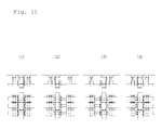
- FIG. 11 shows the procedure in which the device in the embodiment of the present invention is held by vacuum on the glass window surface 32 , and moved along the glass window surface 32 from the left to the right, thereby performing the cleaning for the glass window surface 32 .
- (1) to (4) are four sets of top views and plan views showing four situations of the device in the embodiment of the present invention.
- the four sets of top views and plan views are arranged from the left to the right in the order of time series.
- (1) to (4) show the condition where all of the nine clinging units 4 of the device in the embodiment of the present invention are held by vacuum on the glass window surface 32 , and all of the pneumatic cylinders of the nine pairs of eighteen clinging unit putting forward/backward means 80 are expanded.
- (1) shows the condition where the piston rods of all of the pneumatic cylinders of the six sets of transverse expansion and contraction means 68 and the pneumatic cylinders of the two sets of lengthwise expansion and contraction means 68 are contracted, and all of the transverse running wheels 481 and the lengthwise running wheels 881 are both in the locked state in the nine clinging units 4 .
- FIG. 11 (2) shows the condition where in the three clinging units 4 existing in the longitudinal direction in the left end and the three clinging units 4 existing in the longitudinal direction in the center, the transverse running wheels 481 and the lengthwise running wheels 881 are both in the locked state;
- (3) shows the condition where in the three clinging units 4 existing in the longitudinal direction in the left end and the three clinging units 4 existing in the longitudinal direction in the right end, the transverse running wheels 481 and the lengthwise running wheels 881 are both in the locked state;
- the pneumatic cylinders of the three sets of transverse expansion and contraction means 68 on the left side are expanded, and the pneumatic cylinders of the three sets of transverse expansion and contraction means 68 on the right side are contracted, so that the three clinging units 4 existing in the longitudinal direction in the center are moved from the left to the right.
- FIG. 11 (4) shows the condition where in the three clinging units 4 existing in the longitudinal direction in the right end and the three clinging units 4 existing in the longitudinal direction in the center, the transverse running wheels 481 and the lengthwise running wheels 881 are both in the locked state;
- the pneumatic cylinders of the three sets of transverse expansion and contraction means 68 on the left side are contracted, so that the three clinging units 4 existing in the longitudinal direction in the left end are moved from the left to the right.
- the device in the embodiment of the present invention repeats the situations in the order of (2), (3), (4), and (2) in FIG. 11 , so as to perform the cleaning for the glass window surface 32 while being moved from the left to the right.
- FIG. 12 shows the procedure in which the device in the embodiment of the present invention is held by vacuum on the glass window surface 32 , and moved along the glass window surface 32 from the top to the bottom, thereby performing the cleaning for the glass window surface 32 .
- (1) to (4) are four sets of right side views and plan views showing four situations of the device in the embodiment of the present invention.
- the four sets of right side views and plan views are arranged from the top to the bottom in the order of time series.
- (1) to (4) show the condition where all of the nine clinging units 4 of the device in the embodiment of the present invention are held by vacuum on the glass window surface 32 , and all of the pneumatic cylinders of the nine pairs of eighteen clinging unit putting forward/backward means 80 are expanded.
- (1) shows the condition where the piston rods of all of the pneumatic cylinders of the six sets of transverse expansion and contraction means 68 and the pneumatic cylinders of the two sets of lengthwise expansion and contraction means 68 are contracted, and all of the transverse running wheels 481 and the lengthwise running wheels 881 are both in the locked state in the nine clinging units 4 .
- FIG. 12 (2) shows the condition where in the three clinging units 4 existing in the transverse direction in the upper end and the three clinging units 4 existing in the transverse direction in the center, the transverse running wheels 481 and the lengthwise running wheels 881 are both in the locked state;
- the pneumatic cylinders of the lengthwise expansion and contraction means 68 on the lower side are expanded, so that the three clinging units 4 existing in the transverse direction in the lower end are moved from the top to the bottom.
- (3) shows the condition where in the three clinging units 4 existing in the transverse direction in the upper end and the three clinging units 4 existing in the transverse direction in the lower end, the transverse running wheels 481 and the lengthwise running wheels 881 are both in the locked state;
- the pneumatic cylinders of the lengthwise expansion and contraction means 68 on the upper side are expanded, and the pneumatic cylinders of the lengthwise expansion and contraction means 68 on the lower side are contracted, so that the three clinging units 4 existing in the transverse direction in the center are moved from the top to the bottom.
- FIG. 12 (4) shows the condition where in the three clinging units 4 existing in the transverse direction in the lower end and the three clinging units 4 existing in the transverse direction in the center, the transverse running wheels 481 and the lengthwise running wheels 881 are both in the locked state;
- the pneumatic cylinders of the three sets of lengthwise expansion and contraction means 68 on the upper side are contracted, so that the three clinging units 4 existing in the transverse direction in the upper end are moved from the top to the bottom.
- the device in the embodiment of the present invention repeats the situations in the order of (2), (3), (4), and (2) in FIG. 12 , so as to perform the cleaning for the glass window surface 32 while being moved from the top to the bottom.
- FIG. 13 to FIG. 16 show the procedure in which the device in the embodiment of the present invention is held by vacuum on the glass window surface 32 , moved along the glass window surface 32 from the top to the bottom, and moved by stepping over the window frame 321 , thereby performing the cleaning for the glass window surface 32 .
- (1) to (19) are nineteen sets of right side views and plan views showing nineteen situations of the device in the embodiment of the present invention.
- the nineteen sets of right side views and plan views are arranged from the top to the bottom in the order of time series.
- (1) to (2) show the condition where all of the nine clinging units 4 of the device in the embodiment of the present invention are held by vacuum on the glass window surface 32 , and all of the pneumatic cylinders of the nine pairs of eighteen clinging unit putting forward/backward means 80 are expanded.
- (1) shows the condition where the piston rods of all of the pneumatic cylinders of the six sets of transverse expansion and contraction means 68 and the pneumatic cylinders of the two sets of lengthwise expansion and contraction means 68 are contracted, and all of the transverse running wheels 481 and the lengthwise running wheels 881 are both in the locked state in the nine clinging units 4 .
- FIG. 13 (2) shows the condition where in the three clinging units 4 existing in the transverse direction in the upper end and the three clinging units 4 existing in the transverse direction in the center, the transverse running wheels 481 and the lengthwise running wheels 881 are both in the locked state;
- the pneumatic cylinders of the lengthwise expansion and contraction means 68 on the lower side are expanded, so that the three clinging units 4 existing in the transverse direction in the lower end are moved from the top to the bottom.
- (3) shows the condition where the three clinging units 4 existing in the transverse direction in the upper end and the three clinging units 4 existing in the transverse direction in the center are held by vacuum on the glass window surface 32 ;
- FIG. 13 (4) shows the condition where the three clinging units 4 existing in the transverse direction in the upper end and the three clinging units 4 existing in the transverse direction in the center are held by vacuum on the glass window surface 32 ;
- the pneumatic cylinders of the lengthwise expansion and contraction means 68 on the upper side are expanded, so that the three clinging units 4 existing in the transverse direction in the center are moved from the top to the bottom.
- FIG. 13 (5) shows the condition where the three clinging units 4 existing in the transverse direction in the upper end and the three clinging units 4 existing in the transverse direction in the center are held by vacuum on the glass window surface 32 ;
- the pneumatic cylinders of the lengthwise expansion and contraction means 68 on the upper side are contracted, so that the three clinging units 4 existing in the transverse direction in the upper end are moved from the top to the bottom.
- FIG. 14 (6) shows the condition where the three clinging units 4 existing in the transverse direction in the upper end and the three clinging units 4 existing in the transverse direction in the center are held by vacuum on the glass window surface 32 ;
- the pneumatic cylinders of the lengthwise expansion and contraction means 68 on the upper side are expanded, so that the three clinging units 4 existing in the transverse direction in the center are moved from the top to the bottom.
- FIG. 14 (7) shows the condition where the three clinging units 4 existing in the transverse direction in the upper end and the three clinging units 4 existing in the transverse direction in the center are held by vacuum on the glass window surface 32 ;
- the pneumatic cylinders of the lengthwise expansion and contraction means 68 on the upper side are expanded, so that the three clinging units 4 existing in the transverse direction in the upper end are moved from the top to the bottom.
- FIG. 14 (8) shows the condition where the three clinging units 4 existing in the transverse direction in the upper end and the three clinging units 4 existing in the transverse direction in the center are held by vacuum on the glass window surface 32 ;
- the pneumatic cylinders of the lengthwise expansion and contraction means 68 on the upper side are expanded, so that the three clinging units 4 existing in the transverse direction in the center are moved from the top to the bottom, and the movement is stopped in a place adjacent to the window frame 321 .
- FIG. 14 (9) shows the condition where the three clinging units 4 existing in the transverse direction in the upper end and the three clinging units 4 existing in the transverse direction in the center are held by vacuum on the glass window surface 32 ;
- the pneumatic cylinders of the lengthwise expansion and contraction means 68 on the upper side are expanded, so that the three clinging units 4 existing in the transverse direction in the upper end are moved from the top to the bottom.
- FIG. 14 (10) shows the condition where the three clinging units 4 existing in the transverse direction in the upper end and the three clinging units 4 existing in the transverse direction in the center are held by vacuum on the glass window surface 32 ;
- the three clinging units 4 existing in the transverse direction in the lower end are held by vacuum again on the glass window surface 32 after being moved by stepping over the window frame 321 , so that they can continue the movement along the glass window substrate 32 .
- water spraying means (not shown) is attached to the clinging unit 4 , and the cleaning is performed by the vacuum sealing member 26 while the water is sprayed by the water spraying means.
- the device in the embodiment of the present invention is a device for performing the cleaning for the surface of a window glass while it is held by vacuum on the surface of the window glass and moved along the surface of the window glass, and it is desirable that the device can be moved always in parallel to a perpendicular window frame 321 or always in parallel to a horizontal window frame 321 .
- a window frame contact bumper 169 is attached to the clinging unit frame member 16 , and when the cleaning device is held by vacuum on the glass window surface 32 and moved vertically in a direction toward the horizontal window frame 321 along the glass window surface 32 , the window frame contact bumper 169 is caused to collide with the window frame 321 , and before the collision, the transverse running wheel 481 of the clinging unit 4 existing on the side which does not collide with the window frame 321 is previously protruded toward the glass window surface 32 , so as to be movable in the transverse direction; or
- the posture of the cleaning device is corrected to be parallel to the window frame 321 .
- the device of the present invention for safely and efficiently performing the cleaning operation for the glass window surface or the like of a building via remote control can be effectively applied to various buildings, and particularly to a building of which all of the wall surfaces are glass windows.
- FIG. 1 is a front view showing a preferred embodiment of a device configured in accordance with the present invention.
- FIG. 2 is a right side view of the device shown in FIG. 1 , which shows the condition where clinging unit putting forward/backward means 80 is expanded.
- FIG. 3 is aright side view of the device shown in FIG. 1 , which shows the condition where the clinging unit putting forward/backward means 80 is contracted.
- FIG. 4 is a top view of the device shown in FIG. 1 , which shows the condition where the clinging unit putting forward/backward means 80 is expanded.
- FIG. 5 is a top view of the device shown in FIG. 1 , which shows the condition where the clinging unit putting forward/backward means 80 is contracted.
- FIG. 6 is a fragmentary sectional view in the device shown in FIG. 3 .
- FIG. 7 is an enlarged and fragmentary sectional view of a clinging unit 4 in a lower end in the device shown in FIG. 6 .
- FIG. 8 is an enlarged and fragmentary sectional view of clinging units 4 in an upper end and in the center in the device shown in FIG. 6 .
- FIG. 9 is a rear view of the device shown in FIG. 1 viewed from the direction of a glass window.
- FIG. 10 is an enlarged view of one of nine clinging units 4 in the device shown in FIG. 9 .
- FIG. 11 is a view showing the procedure in which the device shown in FIG. 1 is held by vacuum on a glass window surface 32 , and moved along the glass window surface 32 from the left to the right, thereby performing the cleaning for the glass window surface 32 .
- FIG. 12 is a view showing the procedure in which the device shown in FIG. 1 is held by vacuum on the glass window surface 32 , and moved along the glass window surface 32 from the top to the bottom, thereby performing the cleaning for the glass window surface 32 .
- FIG. 13 is the first one of four views showing the procedure in which the device shown in FIG. 1 is held by vacuum on the glass window surface 32 , moved along the glass window surface 32 from the top to the bottom, and moved by stepping over a window frame, thereby performing the cleaning for the glass window surface 32 .
- FIG. 14 is the second one of the four views showing the procedure in which the device shown in FIG. 1 is held by vacuum on the glass window surface 32 , moved along the glass window surface 32 from the top to the bottom, and moved by stepping over a window frame, thereby performing the cleaning for the glass window surface 32 .
- FIG. 15 is the third one of the four views showing the procedure in which the device shown in FIG. 1 is held by vacuum on the glass window surface 32 , moved along the glass window surface 32 from the top to the bottom, and moved by stepping over a window frame, thereby performing the cleaning for the glass window surface 32 .
- FIG. 16 is the fourth one of the four views showing the procedure in which the device shown in FIG. 1 is held by vacuum on the glass window surface 32 , moved along the glass window surface 32 from the top to the bottom, and moved by stepping over a window frame, thereby performing the cleaning for the glass window surface 32 .
- FIG. 17 is a view showing that, in the device shown in FIG. 1 which is held by vacuum on the glass window surface 32 and is moving downwards and obliquely from the vertical direction, when the window frame contact bumper 161 collides with the horizontal window frame 321 , the device shown in FIG. 1 rotates slightly to the clockwise direction, thereby correcting the posture of the device shown in FIG. 1 to be parallel to the window frame 321 .
Landscapes
- Engineering & Computer Science (AREA)
- Mechanical Engineering (AREA)
- Chemical & Material Sciences (AREA)
- Combustion & Propulsion (AREA)
- Transportation (AREA)
- Robotics (AREA)
- Manipulator (AREA)
- Cleaning In General (AREA)
- Cleaning By Liquid Or Steam (AREA)
Applications Claiming Priority (3)
| Application Number | Priority Date | Filing Date | Title |
|---|---|---|---|
| JP2010207382A JP2012061116A (ja) | 2010-09-15 | 2010-09-15 | 窓ガラスなどの清掃装置 |
| JP2010-207382 | 2010-09-15 | ||
| PCT/JP2011/070659 WO2012036101A2 (fr) | 2010-09-15 | 2011-09-12 | Dispositif de nettoyage pour vitres |
Publications (2)
| Publication Number | Publication Date |
|---|---|
| US20130206492A1 US20130206492A1 (en) | 2013-08-15 |
| US9022159B2 true US9022159B2 (en) | 2015-05-05 |
Family
ID=45832030
Family Applications (1)
| Application Number | Title | Priority Date | Filing Date |
|---|---|---|---|
| US13/823,242 Active 2031-10-01 US9022159B2 (en) | 2010-09-15 | 2011-09-12 | Cleaning device for window glass |
Country Status (5)
| Country | Link |
|---|---|
| US (1) | US9022159B2 (fr) |
| EP (1) | EP2617337B1 (fr) |
| JP (1) | JP2012061116A (fr) |
| KR (1) | KR20140021513A (fr) |
| WO (1) | WO2012036101A2 (fr) |
Cited By (2)
| Publication number | Priority date | Publication date | Assignee | Title |
|---|---|---|---|---|
| US9896139B2 (en) * | 2015-05-27 | 2018-02-20 | Chi-Mou Chao | Robot |
| US11284756B2 (en) * | 2015-12-09 | 2022-03-29 | Alfred Kärcher SE & Co. KG | Window cleaning robot |
Families Citing this family (8)
| Publication number | Priority date | Publication date | Assignee | Title |
|---|---|---|---|---|
| CH705732B1 (de) * | 2011-11-07 | 2016-05-13 | Logistics Wash Holding Ag | Fahrwerk für einen Roboter. |
| CN110432816B (zh) * | 2014-07-25 | 2022-01-18 | 科沃斯家用机器人有限公司 | 吸附式自移动装置 |
| JP2017029280A (ja) * | 2015-07-30 | 2017-02-09 | 東京エレクトロン株式会社 | 清掃装置及び半導体製造システム |
| JP6547230B2 (ja) | 2016-04-03 | 2019-07-24 | ウラカミ合同会社 | 負圧吸着自走ロボット装置 |
| CN106264306B (zh) * | 2016-08-31 | 2018-11-27 | 遵化市悠柠服装设计有限公司 | 一种擦玻璃机器人 |
| CN106983435B (zh) * | 2017-03-14 | 2023-08-01 | 南京斯旭辰智能科技有限公司 | 智能化多功能玻璃幕墙高空清洗设备 |
| CN109419457A (zh) * | 2017-08-25 | 2019-03-05 | 科沃斯机器人股份有限公司 | 多介质智能清洁装置 |
| CN118058644B (zh) * | 2024-04-18 | 2024-06-21 | 河南欢徕科技有限公司 | 一种建筑幕墙清洁装置及其行走方法 |
Citations (5)
| Publication number | Priority date | Publication date | Assignee | Title |
|---|---|---|---|---|
| JPH03104785A (ja) | 1989-09-19 | 1991-05-01 | Ishikawajima Kensa Keisoku Kk | 吸着走行車 |
| JPH0542063A (ja) | 1991-08-12 | 1993-02-23 | Fukashi Uragami | 表面に吸着し且つそれに沿つて移動可能な装置 |
| US5575346A (en) * | 1993-04-27 | 1996-11-19 | Yberle; Hans | Transport device |
| JPH1024875A (ja) | 1996-07-11 | 1998-01-27 | Nippon Kensetsu Kikaika Kyokai | 壁面走行ロボットの足回り装置 |
| US20070235239A1 (en) * | 2004-05-01 | 2007-10-11 | Fukashi Urakami | Device Movable Along Surface of Object |
Family Cites Families (5)
| Publication number | Priority date | Publication date | Assignee | Title |
|---|---|---|---|---|
| JP3365802B2 (ja) * | 1992-12-01 | 2003-01-14 | 健 柳沢 | 歩行ロボット |
| US7155307B2 (en) * | 2001-09-09 | 2006-12-26 | Seemann Henry R | Surface adhering tool carrying robot |
| CN100496368C (zh) * | 2002-09-24 | 2009-06-10 | 三宅彻 | 擦窗装置 |
| DE10320570B4 (de) * | 2003-05-07 | 2005-04-21 | Unique Cleaning Systems Gmbh | Selbstkletterndes Fahrwerk für Fassaden, insbesondere Glasfassaden |
| US20060048800A1 (en) * | 2004-09-09 | 2006-03-09 | Rast Rodger H | Automated building exterior cleaning apparatus |
-
2010
- 2010-09-15 JP JP2010207382A patent/JP2012061116A/ja active Pending
-
2011
- 2011-09-12 KR KR1020137009418A patent/KR20140021513A/ko not_active Ceased
- 2011-09-12 EP EP11825104.0A patent/EP2617337B1/fr not_active Not-in-force
- 2011-09-12 WO PCT/JP2011/070659 patent/WO2012036101A2/fr not_active Ceased
- 2011-09-12 US US13/823,242 patent/US9022159B2/en active Active
Patent Citations (5)
| Publication number | Priority date | Publication date | Assignee | Title |
|---|---|---|---|---|
| JPH03104785A (ja) | 1989-09-19 | 1991-05-01 | Ishikawajima Kensa Keisoku Kk | 吸着走行車 |
| JPH0542063A (ja) | 1991-08-12 | 1993-02-23 | Fukashi Uragami | 表面に吸着し且つそれに沿つて移動可能な装置 |
| US5575346A (en) * | 1993-04-27 | 1996-11-19 | Yberle; Hans | Transport device |
| JPH1024875A (ja) | 1996-07-11 | 1998-01-27 | Nippon Kensetsu Kikaika Kyokai | 壁面走行ロボットの足回り装置 |
| US20070235239A1 (en) * | 2004-05-01 | 2007-10-11 | Fukashi Urakami | Device Movable Along Surface of Object |
Non-Patent Citations (1)
| Title |
|---|
| Official Communication issued in International Patent Application No. PCT/JP2011/070659, mailed on Feb. 21, 2012. |
Cited By (2)
| Publication number | Priority date | Publication date | Assignee | Title |
|---|---|---|---|---|
| US9896139B2 (en) * | 2015-05-27 | 2018-02-20 | Chi-Mou Chao | Robot |
| US11284756B2 (en) * | 2015-12-09 | 2022-03-29 | Alfred Kärcher SE & Co. KG | Window cleaning robot |
Also Published As
| Publication number | Publication date |
|---|---|
| EP2617337A2 (fr) | 2013-07-24 |
| EP2617337A4 (fr) | 2017-09-06 |
| WO2012036101A3 (fr) | 2012-05-31 |
| US20130206492A1 (en) | 2013-08-15 |
| WO2012036101A2 (fr) | 2012-03-22 |
| JP2012061116A (ja) | 2012-03-29 |
| KR20140021513A (ko) | 2014-02-20 |
| EP2617337B1 (fr) | 2019-03-20 |
Similar Documents
| Publication | Publication Date | Title |
|---|---|---|
| US9022159B2 (en) | Cleaning device for window glass | |
| US10774642B1 (en) | Hydraulic support unit and hydraulic support for anti-rock burst roadway | |
| JP2018069223A (ja) | 太陽光パネル保守装置 | |
| US10913164B2 (en) | Suction-adhering and self-propelled robotic device | |
| KR101630224B1 (ko) | 농작물 관리로봇 | |
| CN118266804A (zh) | 清洁机器人 | |
| KR20220022975A (ko) | 고층빌딩 유리창 청소로봇 | |
| CN106958193B (zh) | 弹性自斜坡式流冰防护装置 | |
| CN105980645A (zh) | 车辆多层停放装置和用于对多层停放操作进行管理的方法 | |
| CN107717950A (zh) | 一种方便移动的自动化机械手 | |
| CN204205326U (zh) | 一种九折型材柜体及并柜结构 | |
| CN105563835B (zh) | 单轴移动多轨并联独立式3d打印装置及打印方法 | |
| EP3429948B1 (fr) | Sas de protection résistant à la perforation pour quais de chargement | |
| CN204416513U (zh) | 车门外板钣金件运输装置 | |
| CN102900353A (zh) | 悬梯 | |
| CN222357579U (zh) | 清洁机器人 | |
| CN107901863B (zh) | 一种手动伸缩自锁型卡车侧防护栏装置 | |
| CN205817854U (zh) | 一种带对中功能的全景天窗安装机械手 | |
| CN211381146U (zh) | 一种电梯厢壁清洁装置 | |
| KR101410411B1 (ko) | 오픈 타입 방음벽 | |
| CN214941067U (zh) | 一种高稳定性钢结构减震支座 | |
| CN211989910U (zh) | 一种建筑机械用可移动清洗装置 | |
| CN210948706U (zh) | 用于混凝土喷射的机械手 | |
| CN208605032U (zh) | 一种电力施工设备用安全防护栏 | |
| CN107881955A (zh) | 多功能防冲撞装置 |
Legal Events
| Date | Code | Title | Description |
|---|---|---|---|
| AS | Assignment |
Owner name: URAKAMI LLC, JAPAN Free format text: ASSIGNMENT OF ASSIGNORS INTEREST;ASSIGNOR:URAKAMI, FUKASHI;REEL/FRAME:030291/0597 Effective date: 20130412 Owner name: FUJII DENKO CO., LTD., JAPAN Free format text: ASSIGNMENT OF ASSIGNORS INTEREST;ASSIGNOR:URAKAMI, FUKASHI;REEL/FRAME:030291/0597 Effective date: 20130412 |
|
| STCF | Information on status: patent grant |
Free format text: PATENTED CASE |
|
| MAFP | Maintenance fee payment |
Free format text: PAYMENT OF MAINTENANCE FEE, 4TH YEAR, LARGE ENTITY (ORIGINAL EVENT CODE: M1551); ENTITY STATUS OF PATENT OWNER: LARGE ENTITY Year of fee payment: 4 |
|
| FEPP | Fee payment procedure |
Free format text: MAINTENANCE FEE REMINDER MAILED (ORIGINAL EVENT CODE: REM.); ENTITY STATUS OF PATENT OWNER: LARGE ENTITY |
|
| LAPS | Lapse for failure to pay maintenance fees |
Free format text: PATENT EXPIRED FOR FAILURE TO PAY MAINTENANCE FEES (ORIGINAL EVENT CODE: EXP.); ENTITY STATUS OF PATENT OWNER: LARGE ENTITY |
|
| STCH | Information on status: patent discontinuation |
Free format text: PATENT EXPIRED DUE TO NONPAYMENT OF MAINTENANCE FEES UNDER 37 CFR 1.362 |
|
| FP | Lapsed due to failure to pay maintenance fee |
Effective date: 20230505 |