EP2617347B1 - Endoscope - Google Patents
Endoscope Download PDFInfo
- Publication number
- EP2617347B1 EP2617347B1 EP12817267.3A EP12817267A EP2617347B1 EP 2617347 B1 EP2617347 B1 EP 2617347B1 EP 12817267 A EP12817267 A EP 12817267A EP 2617347 B1 EP2617347 B1 EP 2617347B1
- Authority
- EP
- European Patent Office
- Prior art keywords
- perpendicular directions
- directions
- bending
- bending operation
- touched region
- Prior art date
- Legal status (The legal status is an assumption and is not a legal conclusion. Google has not performed a legal analysis and makes no representation as to the accuracy of the status listed.)
- Not-in-force
Links
Images



Classifications
-
- A—HUMAN NECESSITIES
- A61—MEDICAL OR VETERINARY SCIENCE; HYGIENE
- A61B—DIAGNOSIS; SURGERY; IDENTIFICATION
- A61B1/00—Instruments for performing medical examinations of the interior of cavities or tubes of the body by visual or photographical inspection, e.g. endoscopes; Illuminating arrangements therefor
- A61B1/00002—Operational features of endoscopes
- A61B1/00039—Operational features of endoscopes provided with input arrangements for the user
- A61B1/00042—Operational features of endoscopes provided with input arrangements for the user for mechanical operation
-
- A—HUMAN NECESSITIES
- A61—MEDICAL OR VETERINARY SCIENCE; HYGIENE
- A61B—DIAGNOSIS; SURGERY; IDENTIFICATION
- A61B1/00—Instruments for performing medical examinations of the interior of cavities or tubes of the body by visual or photographical inspection, e.g. endoscopes; Illuminating arrangements therefor
- A61B1/00147—Holding or positioning arrangements
- A61B1/0016—Holding or positioning arrangements using motor drive units
-
- A—HUMAN NECESSITIES
- A61—MEDICAL OR VETERINARY SCIENCE; HYGIENE
- A61B—DIAGNOSIS; SURGERY; IDENTIFICATION
- A61B1/00—Instruments for performing medical examinations of the interior of cavities or tubes of the body by visual or photographical inspection, e.g. endoscopes; Illuminating arrangements therefor
- A61B1/005—Flexible endoscopes
- A61B1/0051—Flexible endoscopes with controlled bending of insertion part
- A61B1/0052—Constructional details of control elements, e.g. handles
-
- A—HUMAN NECESSITIES
- A61—MEDICAL OR VETERINARY SCIENCE; HYGIENE
- A61B—DIAGNOSIS; SURGERY; IDENTIFICATION
- A61B1/00—Instruments for performing medical examinations of the interior of cavities or tubes of the body by visual or photographical inspection, e.g. endoscopes; Illuminating arrangements therefor
- A61B1/04—Instruments for performing medical examinations of the interior of cavities or tubes of the body by visual or photographical inspection, e.g. endoscopes; Illuminating arrangements therefor combined with photographic or television appliances
- A61B1/05—Instruments for performing medical examinations of the interior of cavities or tubes of the body by visual or photographical inspection, e.g. endoscopes; Illuminating arrangements therefor combined with photographic or television appliances characterised by the image sensor, e.g. camera, being in the distal end portion
-
- G—PHYSICS
- G02—OPTICS
- G02B—OPTICAL ELEMENTS, SYSTEMS OR APPARATUS
- G02B23/00—Telescopes, e.g. binoculars; Periscopes; Instruments for viewing the inside of hollow bodies; Viewfinders; Optical aiming or sighting devices
- G02B23/24—Instruments or systems for viewing the inside of hollow bodies, e.g. fibrescopes
- G02B23/2476—Non-optical details, e.g. housings, mountings, supports
Definitions
- the present invention relates to an endoscope including an insertion section provided with a bending section which is configured to bend in first perpendicular directions perpendicular to longitudinal directions and in second perpendicular directions perpendicular to the longitudinal directions and perpendicular to the first perpendicular directions.
- Patent Literature 1 has disclosed an endoscope including an insertion section provided with a bending section which configured to bend in first perpendicular directions perpendicular to longitudinal directions and in second perpendicular directions perpendicular to the longitudinal directions and perpendicular to the first perpendicular directions.
- the first perpendicular directions are up-and-down directions (UD directions) of a subject image obtained by an imaging element
- the second perpendicular directions are left-and-right directions (LR directions) of the subject image.
- a first bending operation knob configured to perform a bending operation in the first perpendicular directions and a second bending operation knob configured to perform a bending operation in the second perpendicular directions are provided on an outer surface of a grip casing of a grip section.
- the second bending operation knob is located to an outside of the first bending operation knob, and provided coaxially with the first bending operation knob.
- Patent Literature 1 Jpn. UM Appln. KOKAI Publication No. 6-68711
- the second bending operation knob is located to the outside of the first bending operation knob, and provided coaxially with the first bending operation knob. Therefore, when a surgeon performs the bending operation in the first perpendicular directions and the bending operation in the second perpendicular directions by one of two hands, a finger of the surgeon does not easily reach the second bending operation knob.
- the second bending operation knob at a position different from that of the first bending operation knob on the outer surface of the grip casing in a state that the second bending operation knob is not coaxial with the first bending operation knob.
- the two bending operation knobs are un-coaxially provided at the different positions with respect to each other, the two bending operation knobs and members configured to transmit the bending operation take up more space in the grip section. Thus, sufficient space is not secured inside the grip casing.
- the present invention has been made in view of the aforementioned problems, and it is an object of the present invention to provide an endoscope in which an inflow of a liquid into an inside of a grip section is effectively prevented, sufficient space is secured inside the grip section, and a bending operation is easily performed.
- an endoscope includes that an insertion section including a bending section which is configured to bend in first perpendicular directions perpendicular to longitudinal directions and in second perpendicular directions perpendicular to the longitudinal directions and perpendicular to the first perpendicular directions; a grip section which includes a grip casing, and which is provided to a proximal direction side of the insertion section; a bending operation knob which is attached to the grip casing, and which is configured to input a bending operation of the bending section in the first perpendicular directions; a touched region detector which includes a touch surface provided in an outer surface of the grip casing and which is configured to detect, over time, a region of the touch surface that has been touched as a touched region when a bending operation of the bending section in the second perpendicular directions is input; a positional information calculator which is configure to calculate a positional information of the detected touched region over time; a positional
- an endoscope in which an inflow of a liquid into an inside of a grip section is effectively prevented, sufficient space is secured inside the grip section, and a bending operation is easily performed, ca be provided.
- a first embodiment of the present invention is described with reference to FIG. 1 to FIG. 11 .
- FIG. 1 and FIG. 2 are views showing an endoscope 1 according to the present embodiment.
- the endoscope 1 includes an insertion section 2 which is configured to be inserted into a body cavity and which extends in longitudinal directions, and a grip section 3 provided to a proximal direction side of the insertion section 2.
- One end of a universal cord 4 is connected to the grip section 3.
- a scope connector (not shown) is provided at the other end of the universal cord 4.
- the insertion portion 2 includes a distal rigid section 6, a bending section 7 provided to the proximal direction side of the distal rigid section 6, and a flexible tube section 8 provided to the proximal direction side of the bending section 7.
- the bending section 7 is configured to bend in first perpendicular directions (a direction of arrow U and a direction of arrow D in FIG. 1 ) perpendicular to the longitudinal directions, and in second perpendicular directions (a direction of arrow L and a direction of arrow R in FIG. 1 ) perpendicular to the longitudinal directions and perpendicular to the first perpendicular directions.
- An imaging element 11 such as a CCD is provided in a distal end portion of the insertion section 2.
- a distal end of an electrical signal line 13 is connected to the imaging element 11.
- a proximal end of the electrical signal line 13 is connected to an image processing unit 15 such as an image processor via the scope connector through an inside of the insertion section 2, an inside of the grip section 3, and an inside of the universal cord 4.
- a light guide (not shown) configured to guide light to illuminate a subject extends from the distal end portion of the insertion section 2 through the inside of the insertion section 2 along the longitudinal directions.
- a proximal end of the light guide is connected to a light source unit (not shown) via the scope connector through the inside of the grip section 3 and the inside of the universal cord 4.
- the first perpendicular directions correspond to up-and-down directions (UD directions) of a subject image obtained (pictured) by the imaging element 11.
- the second perpendicular directions correspond to left-and-right directions (LR directions) of the subject image.
- the grip section 3 includes a grip casing 17 which is an exterior.
- a bending operation knob 19 is attached to the grip casing 17.
- a bending operation of the bending section 7 in the first perpendicular directions is performed (input) by a rotation of the bending operation knob 19.
- the space between the bending operation knob 19 and the grip casing 17 is kept watertight.
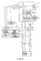
- FIG. 3 is a view showing the configuration of the grip section 3.
- the grip casing 17 includes a first outer surface portion 21 in which an outer surface faces toward one of the second perpendicular directions (the direction of arrow L and the direction of arrow R in FIG. 1 and FIG. 3 ), and a second outer surface portion 22 in which an outer surface faces toward one of the first perpendicular directions (the direction of arrow U and the direction of arrow D in FIG. 1 and FIG. 3 ).
- the bending operation knob 19 is provided on the first outer surface portion 21.
- the bending operation knob 19 is attached to the first outer surface portion 21 so that its rotation axis S is parallel to the second perpendicular directions.
- the bending operation knob 19 is rotated substantially parallel to the first perpendicular directions by the bending operation.
- a first pulley 25 is provided inside the grip casing 17.
- the first pulley 25 is rotated by the bending operation of the bending operation knob 19 in the first perpendicular directions.
- Proximal ends of two first bending wires 27A and 27B are connected to the first pulley 25.
- Distal ends of the first bending wires 27A and 27B are connected to a distal end portion of the bending section 7 through an inside of the flexible tube section 8.
- One of the first bending wires 27A and 27B is pulled by the rotation of the first pulley 25.
- the first bending wire 27A is pulled, the bending section 7 bends toward the direction of arrow U in FIG. 1 .
- the first bending wire 27B is pulled, the bending section 7 bends toward the direction of arrow D in FIG. 1 . In this way, the bending section 7 bends in the first perpendicular directions.
- a slide pad 31 which is a touched region detector is provided to the grip casing 17.
- the bending operation of the bending section 7 in the second perpendicular directions is performed (input) by the slide pad 31.
- the slide pad 31 includes a touch surface 32 located on the second outer surface portion 22 of the outer surface of the grip casing 17.
- the slide pad 31 detects, with time, a region of the touch surface 32 that has been touched as a touched region.
- the slide pad 31 detects, as a touched region, a region that has been touched by a surgeon.
- the control unit 35 includes a positional information calculator 37 configured to calculate a positional information of the detected touched region with time.
- the positional information calculator 37 is configured to calculate a position of a center of gravity of the touched region as the positional information of the touched region.
- the control unit 35 includes a positional change detector 39.
- the positional change detector 39 is configured to detect a positional change of the touched region when the bending operation of the bending section 7 in the second perpendicular directions is performed (input).
- the positional change detector 39 includes a displacement amount calculator 41. The displacement amount calculator 41 will be described in detail later.
- a motor 43 which is a drive member is provided inside the grip casing 17.
- the motor 43 is electrically connected to the control unit 35 via an electrical signal line 45.
- the control unit 35 includes a drive controller 47 configured to control a drive state of the motor 43.
- the drive controller 47 is configured to control the drive state of the motor 43 in accordance with the positional change of the touched region detected by the positional change detector 39.
- An angle sensor 48 is provided inside the grip casing 17.
- the angle sensor 48 is electrically connected to the control unit 35 via an electrical signal line 49.
- the angle sensor 48 is configured to detect a rotation angle of the motor 43.
- the drive controller 47 is configured to control the drive state of the motor 43 in accordance with the detected rotation angle of the motor 43.
- a second pulley 51 is provided inside the grip casing 17.
- the second pulley 51 is rotated when the motor 43 is driven by the bending operation in the second perpendicular directions in the slide pad 31.
- Proximal ends of two second bending wires 53A and 53B are connected to the second pulley 51.
- Distal ends of the second bending wires 53A and 53B are connected to the distal end portion of the bending section 7 through the inside of the flexible tube section 8.
- One of the second bending wires 53A and 53B is pulled by the rotation of the second pulley 51.
- the second bending wire 53A is pulled, the bending section 7 bends toward the direction of arrow L in FIG. 1 .
- the second bending wire 53B is pulled, the bending section 7 bends toward the direction of arrow R in FIG. 1 . In this way, the bending section 7 bends in the second perpendicular directions when the motor 43 is driven.
- FIG. 4 is a diagram illustrating processing in the displacement amount calculator 41.
- a touched region Ai is detected by the slide pad 31 at a time ti.
- the center of gravity Gi of the touched region Ai is calculated by the positional information calculator 37 as positional information of the touched region Ai.
- the position of the touched region is changed by the bending operation of the bending section 7 in the second perpendicular directions.
- a touched region Ai+1 is detected by the slide pad 31 at a time ti+1.
- the center of gravity Gi+1 of the touched region Ai+1 is calculated by the positional information calculator 37 as positional information of the touched region Ai+1.
- the position of the touched region is changed from the center of gravity Gi to the center of gravity Gi+1 by the bending operation of the bending section 7 in the second perpendicular directions.
- the displacement amount calculator 41 calculates a displacement amount of the touched region in the second perpendicular directions (the direction of arrow L and the direction of arrow R in FIG. 4 ) which are reference directions in the positional change of the touched region.
- a displacement amount ⁇ in the second perpendicular directions between the center of gravity Gi and the center of gravity Gi+1 is calculated.
- the drive controller 47 controls the drive state of the motor 43 in accordance with the calculated displacement amount ⁇ of the touched region in the second perpendicular directions. Therefore, the bending portion 7 performs a bending motion in the second perpendicular directions in accordance with the calculated displacement amount ⁇ of the touched region in the second perpendicular directions.
- the present invention is not limited thereto.
- the displacement amount calculator 41 has only to calculate a displacement amount of the touched region in the reference directions parallel to the outer surface of the grip casing 17 during the positional change of the touched region.
- the drive controller 47 has only to control the drive state of the motor 43 in accordance with the displacement amount of the touched region in the reference directions.
- FIG. 5 is a view showing a state in which the surgeon grips the grip casing 17 with one of two hands.
- the bending operation knob 19 is rotated with a thumb F1 to perform (input) the bending operation of the bending section 7 in the first perpendicular directions.
- a forefinger F2 or a middle finger F3 is moved on the touch surface 32 of the slide pad 31 to perform (input) the bending operation of the bending section 7 in the second perpendicular directions.
- a bending operation of a bending section 7A in the first perpendicular directions (the direction of arrow U and the direction of arrow D in FIG. 6 ) is performed by a first bending operation knob 19A
- a bending operation of the bending section 7A in the second perpendicular directions (the direction of arrow L and the direction of arrow R in FIG. 6 ) is performed by a second bending operation knob 31A.
- the second bending operation knob 31A is located to an outside of the first bending operation knob 19A, and provided coaxially with the first bending operation knob 19A.
- the bending operation knob 19 is attached to the first outer surface portion 21 in which the outer surface of the grip casing 17 faces toward one of the second perpendicular directions, and the touch surface 32 of the slide pad 31, which is the touched region detector, is located to the second outer surface portion 22 in which the outer surface of the grip casing 17 faces toward one of the first perpendicular directions. Therefore, when the surgeon grips the grip casing 17 with one hand, the bending operation knob 19 is easily rotated with the thumb F1, and the bending operation of the bending section 7 in the first perpendicular directions is easily performed (input). Moreover, the forefinger F2 or the middle finger F3 is easily moved on the touch surface 32 of the slide pad 31, and the bending operation of the bending section 7 in the second perpendicular directions is easily performed (input).
- the bending operation knob 19 is attached to the first outer surface portion 21 so that its rotation axis S is parallel to the second perpendicular directions.
- the bending operation knob 19 is rotated substantially parallel to the first perpendicular directions by the bending operation.
- the rotation directions of the bending operation knob 19 are substantially parallel to the first perpendicular directions in which the bending portion 7 is bent by the bending operation, the surgeon more easily perform (input) the bending operation of the bending section 7 in the first perpendicular directions.
- the displacement amount calculator 41 calculates the displacement amount ⁇ of the touched region in the second perpendicular directions which are the reference directions in the positional change of the touched region on the touch surface 32.
- the drive state of the motor 43 is controlled in accordance with the displacement amount ⁇ of the touched region in the second perpendicular directions. That is, the bending portion 7 bends in the second perpendicular directions in accordance with the displacement amount ⁇ of the touched region in the second perpendicular directions in the bending operation.
- the bending operation of the bending section 7 in the second perpendicular directions is more easily performed (input).
- the second perpendicular directions in which the bending portion 7 is bent by the bending operation are the reference directions of the displacement amount ⁇ , so that the surgeon more easily perform the bending operation of the bending section 7 in the second perpendicular directions.
- FIG. 7 and FIG. 8 are diagrams illustrating the bending operation of the bending section 7 in the second perpendicular directions.
- the forefinger F2 or the middle finger F3 is moved (arrow B1 in FIG. 7 ) on the touch surface 32 to increase the displacement amount in the second perpendicular directions (the direction of arrow L and the direction of arrow R in FIG. 7 and FIG. 8 ). That is, the forefinger F2 or the middle finger F3 is moved on the touch surface 32 substantially parallel to the second perpendicular directions which are the reference directions.
- FIG. 7 in order to increase the amount (degree) of bending of the bending section 7 in the second perpendicular directions, the forefinger F2 or the middle finger F3 is moved (arrow B1 in FIG. 7 ) on the touch surface 32 to increase the displacement amount in the second perpendicular directions (the direction of arrow L and the direction of arrow R in FIG. 7 and FIG. 8 ). That is, the forefinger F2 or the middle finger F3
- the forefinger F2 or the middle finger F3 is moved (arrow B2 in FIG. 8 ) on the touch surface 32 to decrease the displacement amount in the second perpendicular directions. That is, the forefinger F2 or the middle finger F3 is moved on the touch surface 32 to deviate from the second perpendicular directions which are the reference directions.
- the drive state of a motor 43B is controlled in accordance with an amount (degree) of movement during the positional change of the touched region. That is, when the position is changed from a touched region A'i to a touched region A'i+1 by the bending operation in the second perpendicular directions, an amount of movement ⁇ from the center of gravity G'i to the center of gravity G'i+1 is calculated.
- the drive state of the motor 43B is controlled in accordance with the amount of movement ⁇ , and a bending section 7B performs bending motion in the second perpendicular directions.
- the forefinger F2 or the middle finger F3 is moved (arrow B2 in FIG. 8 ) on the touch surface 32 to decrease the displacement amount in the second perpendicular directions. That is, the forefinger F2 or the middle finger F3 is moved on the touch surface 32 to deviate from the second perpendicular directions which are the reference directions.
- the amount of movement of the forefinger F2 or the middle finger F3 does not need to be decreased as long as the displacement amount of the touched region in the second perpendicular directions is small. Therefore, even when the amount (degree) of bending of the bending section 7 in the second perpendicular directions is small, the surgeon easily performs (inputs) the bending operation of the bending section 7 in the second perpendicular directions.
- an endoscope 1C shown in FIG. 11 as a second comparative example.
- a bending operation of a bending section 7C in the first perpendicular directions (the direction of arrow U and the direction of arrow D in FIG. 11 ) is performed (input) by a first bending operation knob 19C
- a bending operation of the bending section 7C in the second perpendicular directions (the direction of arrow L and the direction of arrow R in FIG. 11 ) is performed (input) by a second bending operation knob 31C.
- the second bending operation knob 31C is provided at a position different from that of the first bending operation knob 19C in a state that the second bending operation knob 31C is not coaxial with the first bending operation knob 19C.
- the bending operation knobs 19C and 31C and members configured to transmit the bending operation take up more space in a grip section 3C. Thus, sufficient space is not secured inside a grip casing 17C.
- the two bending operation knobs 19C and 31C that is rotatable relative to the grip casing 17C are attached to the grip casing 17C at different positions with respect to each other, so that it is difficult to keep the space between each of the bending operation knobs 19C and 31C and the grip casing 17C watertight. This facilitates the inflow of a liquid from the outside of the grip casing 17C into the inside of the grip casing 17C. Therefore, the washing of the grip section 3C after use is difficult.
- the bending operation of the bending section 7 in the second perpendicular directions is performed (input) by the slide pad 31 which is the touched region detector.
- the slide pad 31 is shaped like a flat plate, and therefore takes up less space than the second bending operation knob 31C in the second comparative example.
- Members such as the electrical signal line 33, the motor 43, and the electrical signal line 45, which are configured to allow the second pulley 51 to be rotated by the bending operation in the slide pad 31, also take up little space. Accordingly, sufficient space is secured inside the grip casing 17.
- the slide pad 31 is fixed to the grip casing 17. It is thus easy to keep the space between the slide pad 31 and the grip casing 17 watertight. This efficiently prevents the inflow of a liquid from the outside of the grip casing 17 into the inside of the grip casing 17. Therefore, the grip section 3 is easily washed after use.
- the first perpendicular directions correspond to the up-and-down directions (UD directions) of the subject image obtained (captured) by the imaging element 11, and the second perpendicular directions correspond to the left-and-right directions (LR directions) of the subject image. Therefore, when the bending section 7 is bent in the up-and-down directions, force applied to the bending operation knob 19 by the surgeon is dynamically (mechanically) transmitted to the bending section 7. On the other hand, when the bending section 7 is bent in the left-and-right directions, the motor 42 is driven by an electrical signal generated by the bending operation in the slide pad 31, so that force applied to the slide pad 31 by the surgeon is not dynamically transmitted to the bending section 7.
- the bending section 7 when the bending section 7 is bent, the bending section 7 is bent mainly in the up-and-down directions, and is hardly bent in the left-and-right directions. That is, in the bending operation in the up-and-down directions which is frequently performed, the force applied by the surgeon is dynamically transmitted to the bending section 7. Therefore, the surgeon can feel a proper sense of operation in the bending operation in the up-and-down directions. Consequently, the surgeon more easily performs (inputs) the bending operation of the bending section 7.
- the force applied to the slide pad 31 by the surgeon does not need to be configured to be dynamically transmitted to the bending section 7. That is, even when the surgeon cannot feel a proper sense of operation in the bending operation in the left-and-right directions, there is no great effect on the bending operation of the bending section 7.
- the endoscope 1 having the configuration described above has the following advantageous effects. That is, in the endoscope 1, the bending operation knob 19 is attached to the first outer surface portion 21 in which the outer surface of the grip casing 17 faces toward one of the second perpendicular directions, and the touch surface 32 of the slide pad 31, which is the touched region detector, is located in the second outer surface portion 22 in which the outer surface of the grip casing 17 faces toward one of the first perpendicular directions. Therefore, when the surgeon grips the grip casing 17 with one of two hands, the bending operation knob 19 is easily rotated with the thumb F1, and the bending operation of the bending section 7 in the first perpendicular directions is easily performed (input).
- the forefinger F2 or the middle finger F3 is easily moved on the touch surface 32 of the slide pad 31, and the bending operation of the bending section 7 in the second perpendicular directions is easily performed (input). Consequently, operability in the bending operation of the bending section 7 can be improved.
- the bending operation of the bending section 7 in the second perpendicular directions is performed by the slide pad 31 which is the touched region detector.
- the slide pad 31 is shaped like a flat plate, and therefore takes up little space.
- Members such as the electrical signal line 33, the motor 43, and the electrical signal line 45, which is configured to allow the second pulley 51 to be rotated by the bending operation in the slide pad 31, also take up little space. Accordingly, sufficient space can be secured inside the grip casing 17.
- the slide pad 31 is fixed to the grip casing 17. It is thus possible to easily keep the space between the slide pad 31 and the grip casing 17 watertight. This efficiently prevents the inflow of a liquid from the outside of the grip casing 17 into the inside of the grip casing 17. Therefore, the grip section 3 can be easily washed after use.
Landscapes
- Life Sciences & Earth Sciences (AREA)
- Health & Medical Sciences (AREA)
- Surgery (AREA)
- Engineering & Computer Science (AREA)
- Biophysics (AREA)
- Medical Informatics (AREA)
- Nuclear Medicine, Radiotherapy & Molecular Imaging (AREA)
- Optics & Photonics (AREA)
- Pathology (AREA)
- Radiology & Medical Imaging (AREA)
- Veterinary Medicine (AREA)
- Biomedical Technology (AREA)
- Heart & Thoracic Surgery (AREA)
- Physics & Mathematics (AREA)
- Molecular Biology (AREA)
- Animal Behavior & Ethology (AREA)
- General Health & Medical Sciences (AREA)
- Public Health (AREA)
- Mechanical Engineering (AREA)
- Instruments For Viewing The Inside Of Hollow Bodies (AREA)
- Endoscopes (AREA)
Claims (7)
- Endoscope (1) caractérisé en ce qu'il comprend :une section d'insertion (2) comprenant une section de cintrage (7 ; 7B) qui est configurée pour être cintrée dans des premières directions perpendiculaires, perpendiculaires aux directions longitudinales, et dans des deuxièmes directions perpendiculaires, perpendiculaires aux directions longitudinales et perpendiculaires aux premières directions perpendiculaires ;une section de préhension (3) qui comprend un boîtier de préhension (17), et qui est prévue sur un côté de direction proximale de la section d'insertion (2) ;un bouton (19) d'opération de cintrage qui est fixé au boîtier de préhension (17), et qui est configuré pour délivrer en entrée une opération de cintrage de la section de cintrage (7 ; 7B) dans les premières directions perpendiculaires uniquement ;un élément d'entraînement (43 ; 43B) qui est configuré pour être entraîné pour cintrer la section de cintrage (7 ; 7B) dans les deuxièmes directions perpendiculaires ;caractérisé en ce que l'endoscope comprend en outre :un détecteur (31 ; 31B) de région touchée qui comprend une surface tactile (32 ; 32B) prévue sur une surface externe du boîtier de préhension (17), la surface tactile (32 ; 30B) étant configurée pour délivrer en entrée une opération de cintrage de la section de cintrage (7 ; 7B) dans les deuxièmes directions perpendiculaires uniquement, le détecteur (31 ; 31B) de région touchée étant configuré pour détecter, au fil du temps, une région de la surface tactile (32 ; 32B) qui a été touchée en tant que région touchée (Ai, Ai+1 ; A'i, A'i+1) lorsqu'une opération de cintrage de la section de cintrage (7 ; 7B) dans les deuxièmes directions perpendiculaires est délivrée en entrée dans la surface tactile (32 ; 32B) ;un calculateur (37) d'information de position qui est configuré pour calculer une information de position de la région touchée (Ai, Ai+1 ; A'i, A'i+1) au fil du tempsun détecteur (39) de changement de position qui est configuré pour détecter, conformément à l'information de position de la région touchée (Ai, Ai+1 ; A'i, A'i+1) au fil du temps, un changement de position de la région touchée (Ai, Ai+1 ; A'i, A'i+1) lorsque l'opération de cintrage de la section de cintrage (7 ; 7B) dans les deuxièmes directions perpendiculaires est délivrée en entrée dans la surface tactile (32 ; 32B) ; etun contrôleur d'entraînement (47) qui est configuré pour commander un état d'entraînement de l'élément d'entraînement (43 ; 43B) conformément au changement de position de la région touchée (Ai, Ai+1 ; A'i, A'i+1).
- Endoscope (1) selon la revendication 1, caractérisé en ce que le boîtier de préhension (17) comprend une première partie (21) de surface externe dans laquelle la surface externe est en regard vers l'une des deuxièmes directions perpendiculaires et à laquelle le bouton (19) d'opération de cintrage est fixé dans un état dans lequel un axe de rotation (S) de celui-ci est parallèle aux deuxièmes directions perpendiculaires, et une deuxième partie (22) de surface externe dans laquelle la surface externe est un regard vers l'une des premières directions perpendiculaires et sur laquelle la surface tactile (32 ; 32B) est placée.
- Endoscope (1) selon la revendication 2, caractérisé en ce que le détecteur (39) de changement de position comprend un calculateur (41) de quantité de déplacement qui est configuré pour calculer une quantité (δ) de déplacement de la région touchée (Ai, Ai+1) dans les deuxièmes directions perpendiculaires pendant le changement de position de la région touchée (Ai, Ai+1), et
le contrôleur d'entraînement (47) est configuré pour commander l'état d'entraînement de l'élément d'entraînement (43) conformément à la quantité (δ) de déplacement de la région touchée (Ai, Ai+1) dans les deuxièmes directions perpendiculaires. - Endoscope (1) selon la revendication 1, caractérisé en ce que le détecteur (39) de changement de position comprend un calculateur (41) de quantité de déplacement qui est configuré pour calculer une quantité (δ) de déplacement de la région touchée (Ai, Ai+1) dans les directions de référence parallèles à la surface externe du boîtier de préhension (17) pendant le changement de position de la région touchée (Ai, Ai+1), et
le contrôleur d'entraînement (47) est configuré pour commander l'état d'entraînement de l'élément d'entraînement (43) conformément à la quantité (δ) de déplacement de la région touchée (Ai, Ai+1) dans les directions de référence. - Endoscope (1) selon la revendication 4, caractérisé en ce que les directions de référence sont parallèles aux deuxièmes directions perpendiculaires.
- Endoscope (1) selon la revendication 1, caractérisé en ce qu'il comprend en outre un élément d'imagerie (11) qui est prévu à l'intérieur de la section d'insertion (2), et qui est configuré pour imager un sujet,
dans lequel les premières directions perpendiculaires correspondent aux directions vers le haut et vers le bas d'une image du sujet obtenue par l'élément d'imagerie (11), et les deuxièmes directions perpendiculaires correspondent aux directions vers la gauche et vers la droite de l'image du sujet. - Endoscope (1) selon la revendication 1, caractérisé en ce que le calculateur (37) d'information de position est configuré pour calculer une position d'un centre de gravité (Gi, Gi+ 1 ; G'i, G'i+ 1) de la région touchée (Ai, Ai+ 1 ; A'i, A'i+ 1) en tant qu'information de position de la région touchée (Ai, Ai+1 ; A'i, A'i+1).
Applications Claiming Priority (2)
| Application Number | Priority Date | Filing Date | Title |
|---|---|---|---|
| JP2011165246 | 2011-07-28 | ||
| PCT/JP2012/063347 WO2013015003A1 (fr) | 2011-07-28 | 2012-05-24 | Endoscope |
Publications (3)
| Publication Number | Publication Date |
|---|---|
| EP2617347A1 EP2617347A1 (fr) | 2013-07-24 |
| EP2617347A4 EP2617347A4 (fr) | 2014-01-22 |
| EP2617347B1 true EP2617347B1 (fr) | 2014-12-31 |
Family
ID=47600863
Family Applications (1)
| Application Number | Title | Priority Date | Filing Date |
|---|---|---|---|
| EP12817267.3A Not-in-force EP2617347B1 (fr) | 2011-07-28 | 2012-05-24 | Endoscope |
Country Status (5)
| Country | Link |
|---|---|
| US (1) | US8717427B2 (fr) |
| EP (1) | EP2617347B1 (fr) |
| JP (1) | JP5238102B1 (fr) |
| CN (1) | CN103237490B (fr) |
| WO (1) | WO2013015003A1 (fr) |
Families Citing this family (5)
| Publication number | Priority date | Publication date | Assignee | Title |
|---|---|---|---|---|
| JP5829362B2 (ja) * | 2013-10-02 | 2015-12-09 | オリンパス株式会社 | 導入装置 |
| FR3061909B1 (fr) | 2017-01-19 | 2019-05-24 | S.P.C.M. Sa | Procede de recuperation assistee de petrole par injection d'une composition aqueuse polymerique contenant des microgels |
| FR3063292B1 (fr) | 2017-02-24 | 2020-01-31 | S.P.C.M. Sa | Suspension polyphasique de polymere et son utilisation |
| JP2019000351A (ja) * | 2017-06-15 | 2019-01-10 | オリンパス株式会社 | 内視鏡制御装置、内視鏡システム及びプログラム |
| US12582303B2 (en) * | 2022-11-30 | 2026-03-24 | Karl Storz Imaging, Inc. | Medical scope with capacitive sensor unit |
Family Cites Families (12)
| Publication number | Priority date | Publication date | Assignee | Title |
|---|---|---|---|---|
| CA1222670A (fr) * | 1983-04-29 | 1987-06-09 | Walter P. Siegmund | Methode et appareil pour deflechir la tete d'un endoscope |
| JPS63267326A (ja) * | 1987-04-24 | 1988-11-04 | Olympus Optical Co Ltd | 内視鏡 |
| JPH0668711A (ja) | 1992-08-14 | 1994-03-11 | New Oji Paper Co Ltd | 耐熱絶縁シートの製造方法 |
| JP3387178B2 (ja) * | 1993-11-15 | 2003-03-17 | 富士写真光機株式会社 | 内視鏡の湾曲操作装置 |
| JP3397940B2 (ja) * | 1995-06-30 | 2003-04-21 | オリンパス光学工業株式会社 | 電動湾曲内視鏡装置 |
| US6540670B1 (en) * | 1999-03-19 | 2003-04-01 | Olympus Optical Co., Ltd. | Endoscope system |
| JP3749070B2 (ja) * | 2000-03-16 | 2006-02-22 | オリンパス株式会社 | 内視鏡装置 |
| US6793622B2 (en) * | 2001-09-05 | 2004-09-21 | Olympus Optical Co., Ltd. | Electric bending endoscope |
| JP2004008342A (ja) * | 2002-06-04 | 2004-01-15 | Olympus Corp | 内視鏡 |
| JP4823697B2 (ja) * | 2006-01-13 | 2011-11-24 | オリンパスメディカルシステムズ株式会社 | 電動湾曲内視鏡 |
| JP5295555B2 (ja) * | 2007-12-10 | 2013-09-18 | オリンパスメディカルシステムズ株式会社 | 内視鏡システム |
| JP5484483B2 (ja) * | 2008-12-10 | 2014-05-07 | アンブ・エ/エス | 内視鏡の屈曲部分制御機構 |
-
2012
- 2012-05-24 EP EP12817267.3A patent/EP2617347B1/fr not_active Not-in-force
- 2012-05-24 CN CN201280003770.0A patent/CN103237490B/zh active Active
- 2012-05-24 WO PCT/JP2012/063347 patent/WO2013015003A1/fr not_active Ceased
- 2012-05-24 JP JP2013502940A patent/JP5238102B1/ja active Active
-
2013
- 2013-01-23 US US13/748,185 patent/US8717427B2/en active Active
Also Published As
| Publication number | Publication date |
|---|---|
| JP5238102B1 (ja) | 2013-07-17 |
| CN103237490B (zh) | 2014-11-05 |
| WO2013015003A1 (fr) | 2013-01-31 |
| CN103237490A (zh) | 2013-08-07 |
| US20130201309A1 (en) | 2013-08-08 |
| EP2617347A1 (fr) | 2013-07-24 |
| EP2617347A4 (fr) | 2014-01-22 |
| JPWO2013015003A1 (ja) | 2015-02-23 |
| US8717427B2 (en) | 2014-05-06 |
Similar Documents
| Publication | Publication Date | Title |
|---|---|---|
| JP5930255B2 (ja) | 内視鏡 | |
| US8100825B2 (en) | Endoscope and supportive member for bending operation of the same | |
| JP5274727B2 (ja) | 内視鏡 | |
| EP2617347B1 (fr) | Endoscope | |
| JP6301014B2 (ja) | 湾曲操作装置および内視鏡 | |
| JP6076556B1 (ja) | 湾曲操作装置及び内視鏡 | |
| EP3219247A1 (fr) | Dispositif d'actionnement de courbure et endoscope | |
| JPWO2016143176A1 (ja) | 内視鏡操作部および内視鏡 | |
| EP3248533A1 (fr) | Endoscope | |
| CN114502056B (zh) | 内窥镜的弯曲操作机构和内窥镜 | |
| WO2023090021A1 (fr) | Système de dispositif endoluminal, procédé de commande de dispositif endoluminal et support d'enregistrement de programme informatique pour stocker un programme qui commande un dispositif endoluminal | |
| JPWO2015174128A1 (ja) | 内視鏡 | |
| US20240065534A1 (en) | Endoscope operation part and endoscope | |
| JPWO2017145431A1 (ja) | 内視鏡 | |
| WO2022195703A1 (fr) | Système de manipulateur et procédé de commande de manipulateur | |
| JP6839548B2 (ja) | 内視鏡 |
Legal Events
| Date | Code | Title | Description |
|---|---|---|---|
| PUAI | Public reference made under article 153(3) epc to a published international application that has entered the european phase |
Free format text: ORIGINAL CODE: 0009012 |
|
| 17P | Request for examination filed |
Effective date: 20130419 |
|
| AK | Designated contracting states |
Kind code of ref document: A1 Designated state(s): AL AT BE BG CH CY CZ DE DK EE ES FI FR GB GR HR HU IE IS IT LI LT LU LV MC MK MT NL NO PL PT RO RS SE SI SK SM TR |
|
| A4 | Supplementary search report drawn up and despatched |
Effective date: 20131220 |
|
| RIC1 | Information provided on ipc code assigned before grant |
Ipc: G02B 23/24 20060101ALI20131216BHEP Ipc: A61B 1/00 20060101AFI20131216BHEP |
|
| REG | Reference to a national code |
Ref country code: DE Ref legal event code: R079 Ref document number: 602012004691 Country of ref document: DE Free format text: PREVIOUS MAIN CLASS: A61B0001000000 Ipc: A61B0001005000 |
|
| GRAP | Despatch of communication of intention to grant a patent |
Free format text: ORIGINAL CODE: EPIDOSNIGR1 |
|
| RIC1 | Information provided on ipc code assigned before grant |
Ipc: G02B 23/24 20060101ALI20140508BHEP Ipc: A61B 1/005 20060101AFI20140508BHEP Ipc: A61B 1/00 20060101ALI20140508BHEP |
|
| INTG | Intention to grant announced |
Effective date: 20140522 |
|
| DAX | Request for extension of the european patent (deleted) | ||
| GRAS | Grant fee paid |
Free format text: ORIGINAL CODE: EPIDOSNIGR3 |
|
| GRAP | Despatch of communication of intention to grant a patent |
Free format text: ORIGINAL CODE: EPIDOSNIGR1 |
|
| GRAA | (expected) grant |
Free format text: ORIGINAL CODE: 0009210 |
|
| INTG | Intention to grant announced |
Effective date: 20141112 |
|
| AK | Designated contracting states |
Kind code of ref document: B1 Designated state(s): AL AT BE BG CH CY CZ DE DK EE ES FI FR GB GR HR HU IE IS IT LI LT LU LV MC MK MT NL NO PL PT RO RS SE SI SK SM TR |
|
| REG | Reference to a national code |
Ref country code: CH Ref legal event code: EP Ref country code: GB Ref legal event code: FG4D |
|
| REG | Reference to a national code |
Ref country code: IE Ref legal event code: FG4D |
|
| REG | Reference to a national code |
Ref country code: AT Ref legal event code: REF Ref document number: 703863 Country of ref document: AT Kind code of ref document: T Effective date: 20150215 |
|
| REG | Reference to a national code |
Ref country code: DE Ref legal event code: R096 Ref document number: 602012004691 Country of ref document: DE Effective date: 20150226 |
|
| PG25 | Lapsed in a contracting state [announced via postgrant information from national office to epo] |
Ref country code: FI Free format text: LAPSE BECAUSE OF FAILURE TO SUBMIT A TRANSLATION OF THE DESCRIPTION OR TO PAY THE FEE WITHIN THE PRESCRIBED TIME-LIMIT Effective date: 20141231 Ref country code: LT Free format text: LAPSE BECAUSE OF FAILURE TO SUBMIT A TRANSLATION OF THE DESCRIPTION OR TO PAY THE FEE WITHIN THE PRESCRIBED TIME-LIMIT Effective date: 20141231 Ref country code: NO Free format text: LAPSE BECAUSE OF FAILURE TO SUBMIT A TRANSLATION OF THE DESCRIPTION OR TO PAY THE FEE WITHIN THE PRESCRIBED TIME-LIMIT Effective date: 20150331 |
|
| REG | Reference to a national code |
Ref country code: NL Ref legal event code: VDEP Effective date: 20141231 |
|
| REG | Reference to a national code |
Ref country code: LT Ref legal event code: MG4D |
|
| PG25 | Lapsed in a contracting state [announced via postgrant information from national office to epo] |
Ref country code: RS Free format text: LAPSE BECAUSE OF FAILURE TO SUBMIT A TRANSLATION OF THE DESCRIPTION OR TO PAY THE FEE WITHIN THE PRESCRIBED TIME-LIMIT Effective date: 20141231 Ref country code: GR Free format text: LAPSE BECAUSE OF FAILURE TO SUBMIT A TRANSLATION OF THE DESCRIPTION OR TO PAY THE FEE WITHIN THE PRESCRIBED TIME-LIMIT Effective date: 20150401 Ref country code: SE Free format text: LAPSE BECAUSE OF FAILURE TO SUBMIT A TRANSLATION OF THE DESCRIPTION OR TO PAY THE FEE WITHIN THE PRESCRIBED TIME-LIMIT Effective date: 20141231 Ref country code: HR Free format text: LAPSE BECAUSE OF FAILURE TO SUBMIT A TRANSLATION OF THE DESCRIPTION OR TO PAY THE FEE WITHIN THE PRESCRIBED TIME-LIMIT Effective date: 20141231 Ref country code: LV Free format text: LAPSE BECAUSE OF FAILURE TO SUBMIT A TRANSLATION OF THE DESCRIPTION OR TO PAY THE FEE WITHIN THE PRESCRIBED TIME-LIMIT Effective date: 20141231 |
|
| REG | Reference to a national code |
Ref country code: AT Ref legal event code: MK05 Ref document number: 703863 Country of ref document: AT Kind code of ref document: T Effective date: 20141231 |
|
| PG25 | Lapsed in a contracting state [announced via postgrant information from national office to epo] |
Ref country code: NL Free format text: LAPSE BECAUSE OF FAILURE TO SUBMIT A TRANSLATION OF THE DESCRIPTION OR TO PAY THE FEE WITHIN THE PRESCRIBED TIME-LIMIT Effective date: 20141231 |
|
| PG25 | Lapsed in a contracting state [announced via postgrant information from national office to epo] |
Ref country code: SK Free format text: LAPSE BECAUSE OF FAILURE TO SUBMIT A TRANSLATION OF THE DESCRIPTION OR TO PAY THE FEE WITHIN THE PRESCRIBED TIME-LIMIT Effective date: 20141231 Ref country code: RO Free format text: LAPSE BECAUSE OF FAILURE TO SUBMIT A TRANSLATION OF THE DESCRIPTION OR TO PAY THE FEE WITHIN THE PRESCRIBED TIME-LIMIT Effective date: 20141231 Ref country code: ES Free format text: LAPSE BECAUSE OF FAILURE TO SUBMIT A TRANSLATION OF THE DESCRIPTION OR TO PAY THE FEE WITHIN THE PRESCRIBED TIME-LIMIT Effective date: 20141231 Ref country code: CZ Free format text: LAPSE BECAUSE OF FAILURE TO SUBMIT A TRANSLATION OF THE DESCRIPTION OR TO PAY THE FEE WITHIN THE PRESCRIBED TIME-LIMIT Effective date: 20141231 |
|
| PG25 | Lapsed in a contracting state [announced via postgrant information from national office to epo] |
Ref country code: IS Free format text: LAPSE BECAUSE OF FAILURE TO SUBMIT A TRANSLATION OF THE DESCRIPTION OR TO PAY THE FEE WITHIN THE PRESCRIBED TIME-LIMIT Effective date: 20150430 Ref country code: PL Free format text: LAPSE BECAUSE OF FAILURE TO SUBMIT A TRANSLATION OF THE DESCRIPTION OR TO PAY THE FEE WITHIN THE PRESCRIBED TIME-LIMIT Effective date: 20141231 Ref country code: AT Free format text: LAPSE BECAUSE OF FAILURE TO SUBMIT A TRANSLATION OF THE DESCRIPTION OR TO PAY THE FEE WITHIN THE PRESCRIBED TIME-LIMIT Effective date: 20141231 |
|
| REG | Reference to a national code |
Ref country code: DE Ref legal event code: R097 Ref document number: 602012004691 Country of ref document: DE |
|
| PG25 | Lapsed in a contracting state [announced via postgrant information from national office to epo] |
Ref country code: DK Free format text: LAPSE BECAUSE OF FAILURE TO SUBMIT A TRANSLATION OF THE DESCRIPTION OR TO PAY THE FEE WITHIN THE PRESCRIBED TIME-LIMIT Effective date: 20141231 Ref country code: EE Free format text: LAPSE BECAUSE OF FAILURE TO SUBMIT A TRANSLATION OF THE DESCRIPTION OR TO PAY THE FEE WITHIN THE PRESCRIBED TIME-LIMIT Effective date: 20141231 |
|
| PLBE | No opposition filed within time limit |
Free format text: ORIGINAL CODE: 0009261 |
|
| STAA | Information on the status of an ep patent application or granted ep patent |
Free format text: STATUS: NO OPPOSITION FILED WITHIN TIME LIMIT |
|
| REG | Reference to a national code |
Ref country code: DE Ref legal event code: R082 Ref document number: 602012004691 Country of ref document: DE Representative=s name: WUESTHOFF & WUESTHOFF, PATENTANWAELTE PARTG MB, DE Ref country code: DE Ref legal event code: R081 Ref document number: 602012004691 Country of ref document: DE Owner name: OLYMPUS CORPORATION, JP Free format text: FORMER OWNER: OLYMPUS MEDICAL SYSTEMS CORP., TOKYO, JP |
|
| 26N | No opposition filed |
Effective date: 20151001 |
|
| PG25 | Lapsed in a contracting state [announced via postgrant information from national office to epo] |
Ref country code: IT Free format text: LAPSE BECAUSE OF FAILURE TO SUBMIT A TRANSLATION OF THE DESCRIPTION OR TO PAY THE FEE WITHIN THE PRESCRIBED TIME-LIMIT Effective date: 20141231 |
|
| REG | Reference to a national code |
Ref country code: CH Ref legal event code: PL |
|
| PG25 | Lapsed in a contracting state [announced via postgrant information from national office to epo] |
Ref country code: LI Free format text: LAPSE BECAUSE OF NON-PAYMENT OF DUE FEES Effective date: 20150531 Ref country code: CH Free format text: LAPSE BECAUSE OF NON-PAYMENT OF DUE FEES Effective date: 20150531 Ref country code: MC Free format text: LAPSE BECAUSE OF FAILURE TO SUBMIT A TRANSLATION OF THE DESCRIPTION OR TO PAY THE FEE WITHIN THE PRESCRIBED TIME-LIMIT Effective date: 20141231 Ref country code: LU Free format text: LAPSE BECAUSE OF FAILURE TO SUBMIT A TRANSLATION OF THE DESCRIPTION OR TO PAY THE FEE WITHIN THE PRESCRIBED TIME-LIMIT Effective date: 20150524 |
|
| REG | Reference to a national code |
Ref country code: IE Ref legal event code: MM4A |
|
| REG | Reference to a national code |
Ref country code: FR Ref legal event code: ST Effective date: 20160129 |
|
| PG25 | Lapsed in a contracting state [announced via postgrant information from national office to epo] |
Ref country code: SI Free format text: LAPSE BECAUSE OF FAILURE TO SUBMIT A TRANSLATION OF THE DESCRIPTION OR TO PAY THE FEE WITHIN THE PRESCRIBED TIME-LIMIT Effective date: 20141231 |
|
| PG25 | Lapsed in a contracting state [announced via postgrant information from national office to epo] |
Ref country code: IE Free format text: LAPSE BECAUSE OF NON-PAYMENT OF DUE FEES Effective date: 20150524 |
|
| PG25 | Lapsed in a contracting state [announced via postgrant information from national office to epo] |
Ref country code: FR Free format text: LAPSE BECAUSE OF NON-PAYMENT OF DUE FEES Effective date: 20150601 Ref country code: BE Free format text: LAPSE BECAUSE OF FAILURE TO SUBMIT A TRANSLATION OF THE DESCRIPTION OR TO PAY THE FEE WITHIN THE PRESCRIBED TIME-LIMIT Effective date: 20141231 |
|
| PG25 | Lapsed in a contracting state [announced via postgrant information from national office to epo] |
Ref country code: MT Free format text: LAPSE BECAUSE OF FAILURE TO SUBMIT A TRANSLATION OF THE DESCRIPTION OR TO PAY THE FEE WITHIN THE PRESCRIBED TIME-LIMIT Effective date: 20141231 |
|
| GBPC | Gb: european patent ceased through non-payment of renewal fee |
Effective date: 20160524 |
|
| PG25 | Lapsed in a contracting state [announced via postgrant information from national office to epo] |
Ref country code: SM Free format text: LAPSE BECAUSE OF FAILURE TO SUBMIT A TRANSLATION OF THE DESCRIPTION OR TO PAY THE FEE WITHIN THE PRESCRIBED TIME-LIMIT Effective date: 20141231 Ref country code: GB Free format text: LAPSE BECAUSE OF NON-PAYMENT OF DUE FEES Effective date: 20160524 Ref country code: BG Free format text: LAPSE BECAUSE OF FAILURE TO SUBMIT A TRANSLATION OF THE DESCRIPTION OR TO PAY THE FEE WITHIN THE PRESCRIBED TIME-LIMIT Effective date: 20141231 Ref country code: HU Free format text: LAPSE BECAUSE OF FAILURE TO SUBMIT A TRANSLATION OF THE DESCRIPTION OR TO PAY THE FEE WITHIN THE PRESCRIBED TIME-LIMIT; INVALID AB INITIO Effective date: 20120524 |
|
| PG25 | Lapsed in a contracting state [announced via postgrant information from national office to epo] |
Ref country code: CY Free format text: LAPSE BECAUSE OF FAILURE TO SUBMIT A TRANSLATION OF THE DESCRIPTION OR TO PAY THE FEE WITHIN THE PRESCRIBED TIME-LIMIT Effective date: 20141231 |
|
| PGFP | Annual fee paid to national office [announced via postgrant information from national office to epo] |
Ref country code: DE Payment date: 20170516 Year of fee payment: 6 |
|
| PG25 | Lapsed in a contracting state [announced via postgrant information from national office to epo] |
Ref country code: TR Free format text: LAPSE BECAUSE OF FAILURE TO SUBMIT A TRANSLATION OF THE DESCRIPTION OR TO PAY THE FEE WITHIN THE PRESCRIBED TIME-LIMIT Effective date: 20141231 |
|
| PG25 | Lapsed in a contracting state [announced via postgrant information from national office to epo] |
Ref country code: MK Free format text: LAPSE BECAUSE OF FAILURE TO SUBMIT A TRANSLATION OF THE DESCRIPTION OR TO PAY THE FEE WITHIN THE PRESCRIBED TIME-LIMIT Effective date: 20141231 |
|
| PG25 | Lapsed in a contracting state [announced via postgrant information from national office to epo] |
Ref country code: PT Free format text: LAPSE BECAUSE OF FAILURE TO SUBMIT A TRANSLATION OF THE DESCRIPTION OR TO PAY THE FEE WITHIN THE PRESCRIBED TIME-LIMIT Effective date: 20141231 |
|
| PG25 | Lapsed in a contracting state [announced via postgrant information from national office to epo] |
Ref country code: AL Free format text: LAPSE BECAUSE OF FAILURE TO SUBMIT A TRANSLATION OF THE DESCRIPTION OR TO PAY THE FEE WITHIN THE PRESCRIBED TIME-LIMIT Effective date: 20141231 |
|
| REG | Reference to a national code |
Ref country code: DE Ref legal event code: R119 Ref document number: 602012004691 Country of ref document: DE |
|
| PG25 | Lapsed in a contracting state [announced via postgrant information from national office to epo] |
Ref country code: DE Free format text: LAPSE BECAUSE OF NON-PAYMENT OF DUE FEES Effective date: 20181201 |