EP2618334A1 - Système de surveillance de la puissance d'un réacteur par une sonde de déplacement et procédé de commande d'une sonde de déplacement - Google Patents
Système de surveillance de la puissance d'un réacteur par une sonde de déplacement et procédé de commande d'une sonde de déplacement Download PDFInfo
- Publication number
- EP2618334A1 EP2618334A1 EP20120155111 EP12155111A EP2618334A1 EP 2618334 A1 EP2618334 A1 EP 2618334A1 EP 20120155111 EP20120155111 EP 20120155111 EP 12155111 A EP12155111 A EP 12155111A EP 2618334 A1 EP2618334 A1 EP 2618334A1
- Authority
- EP
- European Patent Office
- Prior art keywords
- drive
- torque
- scheduled
- drive speed
- probe
- Prior art date
- Legal status (The legal status is an assumption and is not a legal conclusion. Google has not performed a legal analysis and makes no representation as to the accuracy of the status listed.)
- Granted
Links
Images




Classifications
-
- G—PHYSICS
- G21—NUCLEAR PHYSICS; NUCLEAR ENGINEERING
- G21C—NUCLEAR REACTORS
- G21C17/00—Monitoring; Testing ; Maintaining
- G21C17/10—Structural combination of fuel element, control rod, reactor core, or moderator structure with sensitive instruments, e.g. for measuring radioactivity, strain
- G21C17/108—Measuring reactor flux
-
- G—PHYSICS
- G21—NUCLEAR PHYSICS; NUCLEAR ENGINEERING
- G21C—NUCLEAR REACTORS
- G21C17/00—Monitoring; Testing ; Maintaining
- G21C17/10—Structural combination of fuel element, control rod, reactor core, or moderator structure with sensitive instruments, e.g. for measuring radioactivity, strain
-
- Y—GENERAL TAGGING OF NEW TECHNOLOGICAL DEVELOPMENTS; GENERAL TAGGING OF CROSS-SECTIONAL TECHNOLOGIES SPANNING OVER SEVERAL SECTIONS OF THE IPC; TECHNICAL SUBJECTS COVERED BY FORMER USPC CROSS-REFERENCE ART COLLECTIONS [XRACs] AND DIGESTS
- Y02—TECHNOLOGIES OR APPLICATIONS FOR MITIGATION OR ADAPTATION AGAINST CLIMATE CHANGE
- Y02E—REDUCTION OF GREENHOUSE GAS [GHG] EMISSIONS, RELATED TO ENERGY GENERATION, TRANSMISSION OR DISTRIBUTION
- Y02E30/00—Energy generation of nuclear origin
- Y02E30/30—Nuclear fission reactors
Definitions
- the present invention relates to traveling reactor power monitoring system that moves a traveling probe in a nuclear reactor by feeding and spooling a probe cable in the reactor. More particularly, the invention is directed to a traveling reactor power monitoring system that moves the traveling probe at optimized drive speeds.
- LPRMs Local Power Range Monitors
- Fissile material provided at the electrode in the LPRMs fissions and releases ionized atoms as a result of being irradiated with neutrons.
- Neutron flux is obtained by measuring the ionized atoms.
- the LPRMs are placed in the reactor constantly and difficult to be replaced, and the sensitivity of the LPRMs declines with time because of consumption of the fissile material. Therefore, the sensitivity of the LPRMs needs to be calibrated arbitrarily in order to measure neutron flux in the reactor precisely.
- a traveling reactor power monitoring system is provided in the nuclear power plant.
- the traveling reactor power monitoring system in the PWR is called a Traversing In-core Probe (TIP) monitoring system.
- TIP Traversing In-core Probe
- This TIP monitoring system moves a traveling probe that is called a TIP in guide tubes provided in the reactor, and the TIP measures neutron flux in the proximity of the LPRMs while moving. By using measured neutron flux, the sensitivity of the LPRMs is calibrated.
- the traveling reactor power monitoring system moves a traveling probe in the reactor, and the sensitivity of the fixed neutron sensors is calibrated by using measured neutron flux by the traveling probe.
- the traveling probe is attached to an edge of a probe cable, and the traveling probe moves in the guide tubes by feeding the probe cable from a storage reel and spooling the probe cable onto the storage reel by a motor.
- This traveling probe measures radioactivity such as neutron and gamma ray as reactor power during moving in the reactor core.
- each guide tube is curved so as to introduce the traveling probe into the reactor core from outside of the reactor pressure vessel. Therefore, in order to reduce the friction while the traveling probe and the probe cable move in the guide tube, the inside of the guide tubes is coated with lubricant.
- Japanese Patent Laid-open Publication No. 2002-71483 discloses a traveling reactor power monitoring system having a torque sensor attached to the motor shaft. And this torque sensor measures the drive torque automatically.
- the above mentioned traveling reactor power monitoring system sets threshold for monitoring the friction as the constant value on the basis of the drive torque at the end point of the guide tube. But the drive torque increases according to the insert distance into the guide tube because the contact area of probe cable and the guide tube increase. Additionally, the drive torque is proportionate to the drive speed of the traveling probe.
- traveling reactor power monitoring system is not able to set appropriate drive speed corresponding to appropriate drive torque at each insert position.
- an abnormal friction is caused by moving the traveling probe at excessively fast drive speed.
- prolonged time of neutron monitoring is taken by moving the TIP at excessively slow drive speed.
- an aspect of the invention provides a traveling reactor power monitoring system that moves the traveling probe at optimized drive speeds that are slow enough to avoid abnormal friction but fast enough to avoid prolonged times of neutron monitoring.
- a traveling reactor power monitoring system includes a probe cable, a traveling probe connected to an edge of the probe cable, a storage reel configured to storage the probe cable, a motor configured to feed the probe cable from the storage reel and spool the probe cable onto the storage reel, a drive control unit configured to drive the motor at a scheduled drive speed, a torque sensor configured to measure a drive torque that is a torque necessary for moving the traveling probe and the probe cable in the guide tubes during the traveling probe moving, an aimed torque DB storing a first threshold and a second threshold at predefined insert position, a drive information DB storing the drive torque received from the torque sensor and the drive speed that the drive control unit moved the traveling probe and a scheduled drive speed processor configured to calculate the scheduled drive speed that is set faster than previous drive speed when the previous drive torque is smaller than the second threshold, and is set slower than previous drive speed when the previous drive torque is larger than the first threshold at each predefined insert position.
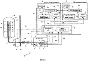
- FIG. 1 is a block schematic diagram illustrating a TIP monitoring system according to first embodiment of the invention.
- Figure 2 is a graphic representation illustrating how to compare the previous drive torque and thresholds1, 2 according to first embodiment of the invention.
- Figure 3 is a graphic representation illustrating how to set the scheduled drive speed according to first embodiment of the invention.
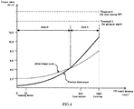
- Figure 4 is a graphic representation illustrating how to compare the previous drive torque and aimed torque curve according to second embodiment of the invention.
- Figure 5 is a graphic representation illustrating how to set the scheduled drive speed according to second embodiment of the invention.
- FIG. 6 is a block schematic diagram illustrating a TIP monitoring system according to third embodiment of the invention.
- FIG.1 shows a general Boiled Water Reactor (BWR) power plant.
- BWR Boiled Water Reactor
- TIP Traversing In-core Prove
- TIP monitoring system 1 moves a traveling probe that is called a TIP 8 in order to measure neutron flux in the reactor core.
- a reactor pressure vessel 32 is stabilized in a reactor container 31, a reactor pressure vessel 32 is stabilized.
- a reactor core 33 is a portion where the fission fuel is loaded in the reactor pressure vessel 32.
- a number of LPRMs 34 are provided in the reactor core 33.
- a number of guide tubes 24 are provided near the LPRMs 34 ( Fig.1 shows one of the number of guide tubes 24.).
- a TIP monitoring system 1 includes a TIP drive unit 2, a probe cable 7, a TIP 8, a drive / monitor device 10, a process calculating machine 13 and a TIP maintenance terminal 14.
- the TIP drive unit 2 has a storage reel 3, a motor 4, a torque sensor 5 and a probe position signal generator 6.
- the drive / monitor device 10, the process calculating machine 13 and the TIP maintenance terminal 14 are provided in a central monitoring room 41.
- the drive / monitor device 10 has a drive control unit 11 and a neutron monitoring unit 12.
- the process calculating machine 13 has a drive information data base (DB) 15a, an aimed torque DB 16a, a scheduled drive speed processor 17a and a neutron monitoring DB 18a.
- the TIP maintenance terminal 14 also has a drive information data base (DB) 15b, an aimed torque DB 16b, a scheduled drive speed processor 17b and a neutron monitoring DB 18b.
- the process calculating machine 13 has a primary function that monitor the power plant condition by receiving the signal from the sensors provided in the power plant (not shown).
- the TIP maintenance terminal 14 has a primary function that monitor the condition of the TIP monitoring system 1, and display and maintenance the abnormal condition (not shown).
- the TIP drive unit 2 is provided outside of the reactor container 31.
- One edge of the probe cable 7 is connected to the TIP 8, and the storage reel 3 may store the probe cable 7.
- the motor 4 is provided so as to feed the probe cable 7 from the storage reel 3 and spool the probe cable 7 onto the storage reel 3 by rotating the storage reel 3.
- the torque sensor 5 is provided so as to measure the drive torque that is a torque necessary for moving the TIP 8 and the probe cable 7 in the guide tubes 24 by the motor 4.
- the probe position signal generator 6 is provided so as to monitor the length of spooling the prove cable 7 onto the reel 3.
- the probe position signal generator 6 may send the monitored cable length as the probe position signal 101.
- the drive control unit 11 is connected to the motor 4 and the indexing device 23 so as to send a drive command 107 to the motor 4 and send an indexing command 108 to the indexing device 23. Furthermore, the drive control unit 11 is connected to the torque sensor 5 and the probe position signal generator 6 so as to receive drive torque information 100 from the torque sensor 5 and receive a probe position signal 101 from the probe position signal generator 6.
- the TIP 8 may send a probe output signal 102 that indicates the measured neutron flux through a signal transmitting line in the probe cable 7.
- the TIP 8 is connected to the neutron monitoring unit 12 so as to send the probe output signal 102 to the neutron monitoring unit 12 through the probe cable 7. Additionally, the neutron monitoring unit 12 is connected to the probe position signal generator 6 so as to receive a probe position signal 101 from the probe position signal generator 6.
- a shielding vessel 21 is provided outside of the reactor container 31.
- the shielding vessel 21 may store and keeps the TIP 8 within.
- a valve assembly 22 is provided outside of the reactor container 31 and inside of the shielding vessel 21.
- an indexing device 23 is provided in the reactor container 31. The shielding vessel 21, the valve assembly 22 and the indexing device 23 are communicated by a pipe so as to move the TIP 8 to the indexing device 23 from the shielding vessel 21 through the valve assembly 22.
- the valve assembly 22 has a gas valve purging gas in the guide tubes 24 and a cutting valve cutting the pipe at emergency situation. Furthermore, the valve assembly 22 closes the pipe without neutron monitoring.
- the guide tubes 24 are connected to the indexing device 23. Each guide tube 24 extends to the under the reactor pressure vessel 32, and curves upwards. Furthermore, each guide tube 24 penetrates the bottom of the reactor pressure vessel 32, and extends vertically into the reactor core 33.
- the drive control unit 11 is connected to the scheduled drive speed processor 17a, 17b so as to receive a scheduled drive speed information 106 from the scheduled drive speed processor 17a or 17b. Furthermore, the drive control unit 11 is connected to the drive information DB 15a, 15b so as to send a current drive information 103 to drive information DB 15a or 15b.
- the scheduled drive speed processor 17a, 17b are connected to the drive information DB 15a, 15b respectively so as to receive a previous drive information 104. Additionally, the scheduled drive speed processor 17a, 17b are connected to the aimed torque DB 16a, 16b respectively so as to receive an aimed torque information 105.
- the neutron monitoring unit 12 is connected to neutron monitoring DB 18a, 18b so as to send a neutron monitoring information 109 to the neutron monitoring DB 18a or 18b.
- the drive information DB 15a is connected to the drive information DB 15b so as to send and receive a synchronizing signal 110 with respect to one another.
- measuring neutron flux is described as follows. Calculating the scheduled drive speed is described later.
- any one of the process calculating machine 13 and the TIP maintenance terminal 14 may measures neutron flux and calculates the scheduled drive speed. The case that the process calculating machine 13 is used is described below.
- the TIP 8 is stored in the shielding vessel 21.
- the drive control unit 11 receives the scheduled drive speed information 106 from the scheduled drive speed processor 17a.
- the scheduled drive speed information 106 indicates the scheduled drive speed that specifies the drive speed of TIP 8 at each insert position in each guide tube 24.
- the drive control unit 11 sends the drive command 107 to the motor 4.
- the motor 4 feeds the probe cable 7 from the storage reel 3, and moves the TIP 8 to the indexing device 23 from the shielding vessel 21.
- the drive control unit 11 sends indexing command 108 to the indexing device 23.
- the indexing device 23 indexes the TIP 8 to the guide tube 24 designated to measure neutron flux indicated in the indexing command 108.
- the drive control unit 11 further drives the motor 4 and insert the TIP 8 into the guide tube 24.
- the drive control unit 11 receives the probe position signal 101 from the probe position signal generator 6, and recognizes the insert position of the TIP 8 in the guide tube 24. At each insert position, the drive control unit 11 moves TIP 8 at the drive speed that the scheduled drive speed information 106 indicates.
- the TIP 8 measures neutron flux as reactor power at the predefined point during moving in the guide tube 24, and sends the probe output signal 102 to the neutron monitoring unit 12 through the probe cable 7. And the neutron monitoring unit 12 receives the probe position signal 101 from the probe position signal generator 6.
- the neutron monitoring unit 12 sends the measured neutron flux at each predefined point as the neutron flux information 109 to the neutron monitoring DB 18a by using the probe output signal 102 and the probe position signal 101.
- This neutron flux information 109 is memorized in the neutron monitoring DB 18a and used for the calibration of the sensitivity of the LPRMs 34.
- the motor control unit 11 After moving the TIP 8 to the predefined end point of the guide tube 24, the motor control unit 11 reverses motor 4 and spools the probe cable 7 onto the storage reel 4, and moves the TIP 8 back to the indexing device 23. If it is necessary to measure neutron flux in another guide tube 24, the motor control unit 11 sends the indexing command 108 to the indexing device 23, and the indexing device 23 indexes the TIP 8 to the other guide tube 24, and the motor control unit 11 moves the TIP 8 in other guide tube 24.
- the motor control unit 11 After moving the TIP 8 in all designated guide tube 24, the motor control unit 11 spools the probe cable 7 onto the storage reel 3 and store the TIP 8 in the shielding vessel 21.
- threshold 1 is used for decreasing the drive speed
- threshold 2 is used for increasing the drive speed
- Threshold 3 is the upper threshold for giving an alarm
- Threshold 4 is the upper threshold for stop moving of the TIP 8.
- threshold 1,2,3 and 4 are configured with respect to each guide tube 24 in advance, because the shape and the length of guide tubes 24 are different each other. Furthermore, according to the insert distance of the TIP 8 into the guide tube 24, the contact area of the probe cable 7 and the guide tube 24 increases, and the drive torque that is a torque necessary for moving the TIP 8 and the probe cable in the guide tube 24 increases. Thus, threshold 1 and 2 are configured so as to increase according to insert distance into the each guide tube 24.
- the drive torque increases more rapidly than the vertical portion per unit distance.
- the width of threshold 1 and 2 at the curved portion are set more widely than the vertical portion (that is, the range between threshold 1 and 2 at the curved portion is greater than the range between threshold 1 and 2 at the vertical portion).
- threshold 1, 2, 3 and 4 The way to set threshold 1, 2, 3 and 4 is described as follows. At first, Ta(x) is measured by moving the TIP8 at past traditional drive speed (Va(x)). Next, Tb(x) is measured by moving the TIP8 at Vb(x). At this point, Vb(x) is 10% faster than Va(x).
- drive torque T increases according to drive speed V.
- This increase rate (r(x)) between drive torque T and drive speed V is described as formula (1).
- Thi(top) is upper limit drive torque at core top. And Thi(top) is set as 80% of the max torque of motor 4. Furthermore, Thi(top) is a value of threshold 1 at core top. Thi(top) is calculated by formula (3) deformed from formula (1).
- Thi top Ta top + r top ⁇ Vhi - Va top
- Ta(top) drive torque when the TIP 8 moved at Va(top) at core top
- Vhi is a drive speed of Thi(top).
- Vhi is a drive speed at core top when the drive torque is Thi(top).
- Vhi is calculated by using formula (4).
- Vhi Va top + Thi top - Ta top / r top
- Thi(x) is a drive speed when the TIP 8 moved at Vhi constantly at each insert distance. Threshold 1 is gained by smoothing Thi(x) at each insert distance. Thi(x) is calculated by formula (5)
- Thi x Ta x + r x ⁇ Vhi - Va x
- Tlo(top) is lower limit drive torque at core top. And Tlo(top) is set as 60% of the max torque of motor 4. Furthermore, Tlo(top) is a value of threshold 2 at core top. Tlo(top) is calculated by formula (6)
- Vlo Va top + Tlo top - Ta top / r top
- Tlo(x) is a drive speed when the TIP 8 moved at Vlo constantly at each insert distance. Threshold 1 is gained by smoothing Tlo(x) at each insert distance. Tlo(x) is calculated by formula (7)
- Tlo x Ta x + r x ⁇ Vlo - Va x
- threshold 1, 2, 3 and 4 Another way to set threshold 1, 2, 3 and 4 is described as follows.
- the normal drive torque curve is measured with respect to each guide tube 24 along all insert distance in the normal status at plant routine checkup. This normal drive torque curve may be measured multiple times and averaged or smoothed.
- the threshold 1 is gained by adding the predefined value to the normal drive torque at each insert distance
- threshold 2 is gained by subtracting the predefined value from the normal drive torque at each insert distance.
- normal drive torque curve is also gained by measuring the normal drive torque at the end point and the inlet point of the guide tube 24, and fitting these normal drive torque so as to draw smoothed curve.
- threshold 3 is set as 90 % of the max torque drive value of the motor 4
- threshold 4 is set as 95 % of the max torque drive value.
- the scheduled drive speed processor 17a receives the aimed torque information 105 from the aimed torque DB 16a. Additionally, the scheduled drive speed processor 17a receives the previous drive speed and the previous drive torque as previous drive information 104 from drive information DB 15a. This previous drive speed is the drive speed at previous neutron monitoring, and this previous drive torque is the drive torque measured at previous neutron monitoring. The scheduled drive speed processor 17a compares the threshold 1, 2 and the previous drive torque, and sets the scheduled drive speed by increasing and decreasing from the previous drive speed.
- Figs. 2 and 3 Processing carried out by the scheduled drive speed processor 17a is now described with reference to Figs. 2 and 3 .
- the previous drive torque is smaller than the threshold 2.
- the scheduled drive speed is set faster than previous drive speed as shown Fig.3 .
- the previous drive torque is located between threshold 1 and 2.
- the scheduled drive speed is set as same as the previous drive speed as shown Fig.3 .
- the previous drive torque is larger than the threshold 1.
- the scheduled drive speed is set slower than previous drive speed as shown Fig.3 .
- the all insert distance is separated into a number of minim intervals. And above mentioned scheduled drive speed is at each minim At each minim interval, the previous drive speed, threshold 1, and threshold 2 are considered constant value.
- Increase and decrease range of the drive speed is calculated by using following formula (8) and (9).
- V t ⁇ 0 - t ⁇ 1 / t ⁇ 0 ⁇ V ⁇ 1 ⁇ W
- V ⁇ 2 V ⁇ 1 + ? V
- V1 previous drive speed
- V2 scheduled drive speed
- the torque variable number t0 is configured as threshold 1.
- the torque variable number t0 is configured as threshold 2.
- the torque number t 1 is smaller than threshold 1.and larger than threshold 2, such as zone B, the torque number t0 is configured previous drive torque t 1, and the scheduled drive speed is maintained at previous drive speed.
- the weighting factor W is the factor protecting rapid change of scheduled drive speed, configured as 0 ⁇ W ⁇ 1.0, and adjusted as needed.
- the max drive torque value among the drive torque value measured in this minim interval can be applied to the previous drive torque, By doing so, it is possible to improve safeness.
- the scheduled drive speed processor 17a calculates the scheduled drive speed at each minim intervals, and sends these scheduled drive speeds as the scheduled drive speed information 106 to the drive control unit 11. At this point, threshold 3 and 4 are added to this scheduled drive speed information 106.
- the drive control unit 11 receives the scheduled drive speed information 106, and sends drive command 107 to the motor 4, and moves TIP 8 at the scheduled drive speed indicated in the scheduled drive speed information 106 at each insert position.
- the torque sensor 5 measures the drive torque, and sends this drive torque as the drive torque information 100 to the drive control unit 11 while TIP 8 is moving.
- the drive control unit 11 receives the drive torque information 100, and compares the drive torque and threshold 3, 4. If the drive torque exceeds threshold 3, the drive control unit 11 sends the alarm signal to the process calculation machine 13 or TIP maintenance terminal 14 (not shown), and the process calculation machine 13 or TIP maintenance terminal 14 signals an alarm.
- the drive control unit 11 stop moving the TIP 8, and reverses the motor 4 and retrieves the TIP 8 by predefined length, and insert again at slower drive speed. If the drive torque exceeds threshold 4 again, the drive control unit 11 withdraws the TIP 8 again, and inserts the TIP 8 at further slower drive speed. When the drive torque continues to exceed threshold 4 at predefined slower speed, the drive control unit 11 stops driving the motor 4.
- the drive control unit 11 stops moving the TIP 8, and withdraws the TIP 8, and inserts again at same drive speed. If the drive torque underruns threshold 4, the drive control unit 11 continues moving the TIP 8. If the drive torque exceeds threshold 4 again, the drive control unit 11 inserts the TIP 8 again at same drive speed. When the drive torque exceeds threshold 4 at predefined times, the drive control unit 11 stop driving the motor 4. In this modification, the drive control unit 11 can inserts the TIP 8 more quickly. Above inserting formula can be carried out at not only during inserting the TIP 8 into the guide tube 24 but also during drawing the TIP 8 from the guide tube 24.
- the drive control unit 11 homologizes the drive speed and the drive torque at each insert position by using the probe position signal 101, the drive torque information 100 at current neutron monitoring. And the drive control unit 11 sends this information as the current drive information 103 to the drive information DB 15a.
- the current drive information 103 memorize in the drive information DB 15a is used for next calculation of the scheduled drive speed.
- the drive information DB 15a and 15b update each other by sending and receiving the synchronizing signal 110 that indicates drive information so far. Furthermore, it is possible to select normal one within the process calculation machine 13 and/or the TIP maintenance terminal 14 by detecting the break of synchronizing signal 110 or bad condition of other one.
- this embodiment may be modified as below. At each minim interval, the averaged drive torque value among the drive torque value measured in this minim interval may be applied to the previous drive torque. In this modification, it is possible to prevent the control incapability and control more stably.
- This embodiment differs from the first embodiment in that the scheduled drive speed processor 17a, 17b calculates the scheduled drive speed by using an aimed torque curve.
- Tmid(top) is aimed drive torque at core top. And Tmid(top) is set as 70% of the max torque of motor 4. Tmid(top) is calculated by formula (10)
- Vmid Va top + Tmid top - Ta top / r top
- Tmid (x) is a drive speed when the TIP 8 moved at Vmid constantly at each insert distance.
- the aimed drive torque 1 is gained by smoothing Tmid(x) at each insert distance.
- Tmid(x) is calculated by formula (11)
- Tmid x Ta x + r x ⁇ Vmid - Va x
- the normal drive torque curve measured with respect to each guide tube 24 along all insert distance in the normal status at plant routine checkup is applied to the aimed torque curve.
- This aimed torque curve is stored in the aimed torque DB 16a, 16b.
- the previous drive torque is smaller than the aimed torque curve.
- the scheduled drive speed is set faster than previous drive speed as shown Fig.5 .
- the previous drive torque is larger than the aimed torque curve.
- the scheduled drive speed is set slower than previous drive speed as shown Fig.5 .
- Increase and decrease range of the drive speed is calculated by above formulae (8) and (9).
- the torque variable number t0 is configured as the value of the aimed torque curve at each minim interval.
- FIG. 6 is a block schematic diagram illustrating a TIP monitoring system according to third embodiment of the invention.
- This embodiment differs from the first embodiment in that TIP monitoring system 1 additionally has a maintenance information display device 19a, b in the process calculating machine 13 and TIP maintenance terminal 14 respectively.
- the maintenance information display device 19a, b are connected to the drive information DB 15a, b respectively so as to receive a maintenance information signal 111.
- the maintenance information display device 19a receives the maintenance information signal 111 from the drive information DB 15a.
- This maintenance information signal 111 indicates past multiple drive torque records of each guide tube 24.
- the maintenance information display device 19a calculates a predicted drive torque of next time neutron measurement. For example, this predicted drive torque is calculated by linear prediction of past multiple drive torque at each inset distance.
- the maintenance information display device 19a displays maintenance information by using a LCD monitor or a projector.
- maintenance information includes the guide tube 24 and insertion distance where the predicted drive torque exceeds the threshold 4. Additionally, displaying this information just after moving the TIP 8 at each guide tube 24, it is able to maintenance the TIP monitoring system 1 promptly.
- guide tubes 24 penetrates upper portion of the reactor pressure vessel, and the traveling probe moves to the core bottom form the core top.
- drive torque increases according to insert distance to the core bottom.
- threshold 1, 2 and aimed torque curve are defined to increase according to insert distance to the core bottom.
- the traveling power monitoring system can connect a gamma thermo meter as the traveling probe.
- This gamma thermo meter can measure gamma ray in the reactor core during moving.
- the traveling power monitoring system is able to measure gamma ray as reactor power.
- scheduled drive speed processor 17a, 17b are able to use not only previous drive information 104 but also the forepast drive information that indicates the forepast drive speed and the forepast drive torque.
- the forepast drive information includes the before last time drive speed and the drive torque, the average value of the previous and the before last time drive speed and drive torque end so on.
- the drive information DB 15a, 15b are able to store the forepast drive information that is previously measured at other power plant. By doing so, it is possible to optimize the drive speed without measuring and storing the forepast drive information of the plant under operation.
- the scheduled drive speed processor 17a, 17b can calculate the scheduled drive speed at the predefined insert position. For example, the scheduled drive speed processor 17a, 17b can calculate the scheduled drive at intervals of 10 or 20 inch in one guide tube 24.
- the aimed torque DB 16a, 16b memorize threshold 1, 2 or aimed torque threshold at the predefined insert position at least.
- the drive information DB 15a, 15b stores the drive information at the predefined insertion position at least.
- the drive torque changes rapidly at the curved portion of the guide tube 24 compared to other potion.
Landscapes
- Physics & Mathematics (AREA)
- Engineering & Computer Science (AREA)
- Plasma & Fusion (AREA)
- General Engineering & Computer Science (AREA)
- High Energy & Nuclear Physics (AREA)
- Monitoring And Testing Of Nuclear Reactors (AREA)
Applications Claiming Priority (1)
| Application Number | Priority Date | Filing Date | Title |
|---|---|---|---|
| JP2012008416A JP2013148430A (ja) | 2012-01-18 | 2012-01-18 | 移動式原子炉出力測定装置およびその移動式検出器の駆動方法 |
Publications (2)
| Publication Number | Publication Date |
|---|---|
| EP2618334A1 true EP2618334A1 (fr) | 2013-07-24 |
| EP2618334B1 EP2618334B1 (fr) | 2015-11-25 |
Family
ID=45562901
Family Applications (1)
| Application Number | Title | Priority Date | Filing Date |
|---|---|---|---|
| EP12155111.3A Not-in-force EP2618334B1 (fr) | 2012-01-18 | 2012-02-13 | Système de surveillance de la puissance d'un réacteur par une sonde de déplacement et procédé de commande d'une sonde de déplacement |
Country Status (3)
| Country | Link |
|---|---|
| US (1) | US20130182810A1 (fr) |
| EP (1) | EP2618334B1 (fr) |
| JP (1) | JP2013148430A (fr) |
Citations (2)
| Publication number | Priority date | Publication date | Assignee | Title |
|---|---|---|---|---|
| JP2002071483A (ja) | 2000-08-31 | 2002-03-08 | Toshiba Corp | 移動式炉内計装系トルク測定装置 |
| JP2006145417A (ja) * | 2004-11-22 | 2006-06-08 | Toshiba Corp | 移動式原子炉内中性子測定装置およびその方法 |
Family Cites Families (1)
| Publication number | Priority date | Publication date | Assignee | Title |
|---|---|---|---|---|
| US6527130B2 (en) * | 2001-02-16 | 2003-03-04 | General Electric Co. | Method and system for load measurement in a crane hoist |
-
2012
- 2012-01-18 JP JP2012008416A patent/JP2013148430A/ja active Pending
- 2012-02-13 EP EP12155111.3A patent/EP2618334B1/fr not_active Not-in-force
- 2012-02-16 US US13/397,913 patent/US20130182810A1/en not_active Abandoned
Patent Citations (2)
| Publication number | Priority date | Publication date | Assignee | Title |
|---|---|---|---|---|
| JP2002071483A (ja) | 2000-08-31 | 2002-03-08 | Toshiba Corp | 移動式炉内計装系トルク測定装置 |
| JP2006145417A (ja) * | 2004-11-22 | 2006-06-08 | Toshiba Corp | 移動式原子炉内中性子測定装置およびその方法 |
Also Published As
| Publication number | Publication date |
|---|---|
| JP2013148430A (ja) | 2013-08-01 |
| US20130182810A1 (en) | 2013-07-18 |
| EP2618334B1 (fr) | 2015-11-25 |
Similar Documents
| Publication | Publication Date | Title |
|---|---|---|
| EP2418650A1 (fr) | Unité de commande de sonde interne traversante et procédé pour surveiller la friction à lýintérieur des tubes guides | |
| US6181759B1 (en) | Method and apparatus for determining nearness to criticality of a nuclear fueled electric power generating unit | |
| US20120160819A1 (en) | Wire feed speed measurement device | |
| EP2645372A2 (fr) | Système mobile de surveillance de puissance d'un réacteur et procédé de commande de rétractation de sonde | |
| EP2618334B1 (fr) | Système de surveillance de la puissance d'un réacteur par une sonde de déplacement et procédé de commande d'une sonde de déplacement | |
| EP2639796B1 (fr) | Système traversant de surveillance de puissance d'un réacteur et procédé de surveillance de couple d'entraînement | |
| JP4592397B2 (ja) | 移動式原子炉内中性子測定装置およびその方法 | |
| EP0052445A1 (fr) | Dispositif de mesure de la densité de flux neutronique dans un réacteur nucléaire | |
| US9305670B2 (en) | TIP system and TIP monitoring control equipment | |
| EP0469753B1 (fr) | Système de distribution de détecteurs de flux neutronique pour système de relevé de carte de flux de réacteur nucléaire | |
| JP5722195B2 (ja) | 水位検出システム及び方法 | |
| EP4154276B1 (fr) | Procédé et système de mesure périodique de l'activité de rayonnement gamma total d'un radio-isotope cible produit à l'intérieur du coeur d'un réacteur nucléaire | |
| CN109983540A (zh) | 堆芯核仪表装置 | |
| CN114895348A (zh) | 沉淀反应器核临界安全的监测系统 | |
| KR101373041B1 (ko) | 중수로 이동형 검출기 구동장치 | |
| JP2017026451A (ja) | 臨界監視システム及び臨界監視方法 | |
| JP5305335B2 (ja) | 核出力計測装置 | |
| KR20240072913A (ko) | 줄 길이 계측 장치 및 이것을 구비한 낚시용 릴 | |
| JPH01150894A (ja) | モータ駆動制御装置 | |
| CN114895342A (zh) | 沉淀反应器核临界安全的监测系统 | |
| CN121439299A (zh) | 一种反应堆中子注量率的异常监测方法、装置及设备 | |
| JPH06308281A (ja) | 可動インコアプローブモニタ | |
| JPS58140690A (ja) | 監視lprm選択表示装置 |
Legal Events
| Date | Code | Title | Description |
|---|---|---|---|
| PUAI | Public reference made under article 153(3) epc to a published international application that has entered the european phase |
Free format text: ORIGINAL CODE: 0009012 |
|
| 17P | Request for examination filed |
Effective date: 20120213 |
|
| AK | Designated contracting states |
Kind code of ref document: A1 Designated state(s): AL AT BE BG CH CY CZ DE DK EE ES FI FR GB GR HR HU IE IS IT LI LT LU LV MC MK MT NL NO PL PT RO RS SE SI SK SM TR |
|
| AX | Request for extension of the european patent |
Extension state: BA ME |
|
| 17Q | First examination report despatched |
Effective date: 20131111 |
|
| GRAP | Despatch of communication of intention to grant a patent |
Free format text: ORIGINAL CODE: EPIDOSNIGR1 |
|
| RIC1 | Information provided on ipc code assigned before grant |
Ipc: G21C 17/10 20060101AFI20150512BHEP Ipc: G21C 17/108 20060101ALI20150512BHEP |
|
| INTG | Intention to grant announced |
Effective date: 20150605 |
|
| GRAS | Grant fee paid |
Free format text: ORIGINAL CODE: EPIDOSNIGR3 |
|
| GRAA | (expected) grant |
Free format text: ORIGINAL CODE: 0009210 |
|
| AK | Designated contracting states |
Kind code of ref document: B1 Designated state(s): AL AT BE BG CH CY CZ DE DK EE ES FI FR GB GR HR HU IE IS IT LI LT LU LV MC MK MT NL NO PL PT RO RS SE SI SK SM TR |
|
| REG | Reference to a national code |
Ref country code: GB Ref legal event code: FG4D |
|
| REG | Reference to a national code |
Ref country code: CH Ref legal event code: EP |
|
| REG | Reference to a national code |
Ref country code: AT Ref legal event code: REF Ref document number: 762959 Country of ref document: AT Kind code of ref document: T Effective date: 20151215 |
|
| REG | Reference to a national code |
Ref country code: IE Ref legal event code: FG4D |
|
| REG | Reference to a national code |
Ref country code: DE Ref legal event code: R096 Ref document number: 602012012550 Country of ref document: DE |
|
| REG | Reference to a national code |
Ref country code: FR Ref legal event code: PLFP Year of fee payment: 5 |
|
| REG | Reference to a national code |
Ref country code: LT Ref legal event code: MG4D |
|
| REG | Reference to a national code |
Ref country code: NL Ref legal event code: MP Effective date: 20160225 |
|
| REG | Reference to a national code |
Ref country code: AT Ref legal event code: MK05 Ref document number: 762959 Country of ref document: AT Kind code of ref document: T Effective date: 20151125 |
|
| PG25 | Lapsed in a contracting state [announced via postgrant information from national office to epo] |
Ref country code: NO Free format text: LAPSE BECAUSE OF FAILURE TO SUBMIT A TRANSLATION OF THE DESCRIPTION OR TO PAY THE FEE WITHIN THE PRESCRIBED TIME-LIMIT Effective date: 20160225 Ref country code: IS Free format text: LAPSE BECAUSE OF FAILURE TO SUBMIT A TRANSLATION OF THE DESCRIPTION OR TO PAY THE FEE WITHIN THE PRESCRIBED TIME-LIMIT Effective date: 20160325 Ref country code: HR Free format text: LAPSE BECAUSE OF FAILURE TO SUBMIT A TRANSLATION OF THE DESCRIPTION OR TO PAY THE FEE WITHIN THE PRESCRIBED TIME-LIMIT Effective date: 20151125 Ref country code: ES Free format text: LAPSE BECAUSE OF FAILURE TO SUBMIT A TRANSLATION OF THE DESCRIPTION OR TO PAY THE FEE WITHIN THE PRESCRIBED TIME-LIMIT Effective date: 20151125 Ref country code: NL Free format text: LAPSE BECAUSE OF FAILURE TO SUBMIT A TRANSLATION OF THE DESCRIPTION OR TO PAY THE FEE WITHIN THE PRESCRIBED TIME-LIMIT Effective date: 20151125 Ref country code: LT Free format text: LAPSE BECAUSE OF FAILURE TO SUBMIT A TRANSLATION OF THE DESCRIPTION OR TO PAY THE FEE WITHIN THE PRESCRIBED TIME-LIMIT Effective date: 20151125 |
|
| PG25 | Lapsed in a contracting state [announced via postgrant information from national office to epo] |
Ref country code: PL Free format text: LAPSE BECAUSE OF FAILURE TO SUBMIT A TRANSLATION OF THE DESCRIPTION OR TO PAY THE FEE WITHIN THE PRESCRIBED TIME-LIMIT Effective date: 20151125 Ref country code: SE Free format text: LAPSE BECAUSE OF FAILURE TO SUBMIT A TRANSLATION OF THE DESCRIPTION OR TO PAY THE FEE WITHIN THE PRESCRIBED TIME-LIMIT Effective date: 20151125 Ref country code: BE Free format text: LAPSE BECAUSE OF NON-PAYMENT OF DUE FEES Effective date: 20160229 Ref country code: AT Free format text: LAPSE BECAUSE OF FAILURE TO SUBMIT A TRANSLATION OF THE DESCRIPTION OR TO PAY THE FEE WITHIN THE PRESCRIBED TIME-LIMIT Effective date: 20151125 Ref country code: GR Free format text: LAPSE BECAUSE OF FAILURE TO SUBMIT A TRANSLATION OF THE DESCRIPTION OR TO PAY THE FEE WITHIN THE PRESCRIBED TIME-LIMIT Effective date: 20160226 Ref country code: LV Free format text: LAPSE BECAUSE OF FAILURE TO SUBMIT A TRANSLATION OF THE DESCRIPTION OR TO PAY THE FEE WITHIN THE PRESCRIBED TIME-LIMIT Effective date: 20151125 Ref country code: FI Free format text: LAPSE BECAUSE OF FAILURE TO SUBMIT A TRANSLATION OF THE DESCRIPTION OR TO PAY THE FEE WITHIN THE PRESCRIBED TIME-LIMIT Effective date: 20151125 Ref country code: RS Free format text: LAPSE BECAUSE OF FAILURE TO SUBMIT A TRANSLATION OF THE DESCRIPTION OR TO PAY THE FEE WITHIN THE PRESCRIBED TIME-LIMIT Effective date: 20151125 Ref country code: PT Free format text: LAPSE BECAUSE OF FAILURE TO SUBMIT A TRANSLATION OF THE DESCRIPTION OR TO PAY THE FEE WITHIN THE PRESCRIBED TIME-LIMIT Effective date: 20160325 |
|
| PG25 | Lapsed in a contracting state [announced via postgrant information from national office to epo] |
Ref country code: IT Free format text: LAPSE BECAUSE OF FAILURE TO SUBMIT A TRANSLATION OF THE DESCRIPTION OR TO PAY THE FEE WITHIN THE PRESCRIBED TIME-LIMIT Effective date: 20151125 Ref country code: CZ Free format text: LAPSE BECAUSE OF FAILURE TO SUBMIT A TRANSLATION OF THE DESCRIPTION OR TO PAY THE FEE WITHIN THE PRESCRIBED TIME-LIMIT Effective date: 20151125 |
|
| REG | Reference to a national code |
Ref country code: DE Ref legal event code: R097 Ref document number: 602012012550 Country of ref document: DE |
|
| PG25 | Lapsed in a contracting state [announced via postgrant information from national office to epo] |
Ref country code: SK Free format text: LAPSE BECAUSE OF FAILURE TO SUBMIT A TRANSLATION OF THE DESCRIPTION OR TO PAY THE FEE WITHIN THE PRESCRIBED TIME-LIMIT Effective date: 20151125 Ref country code: RO Free format text: LAPSE BECAUSE OF FAILURE TO SUBMIT A TRANSLATION OF THE DESCRIPTION OR TO PAY THE FEE WITHIN THE PRESCRIBED TIME-LIMIT Effective date: 20151125 Ref country code: EE Free format text: LAPSE BECAUSE OF FAILURE TO SUBMIT A TRANSLATION OF THE DESCRIPTION OR TO PAY THE FEE WITHIN THE PRESCRIBED TIME-LIMIT Effective date: 20151125 Ref country code: SM Free format text: LAPSE BECAUSE OF FAILURE TO SUBMIT A TRANSLATION OF THE DESCRIPTION OR TO PAY THE FEE WITHIN THE PRESCRIBED TIME-LIMIT Effective date: 20151125 Ref country code: DK Free format text: LAPSE BECAUSE OF FAILURE TO SUBMIT A TRANSLATION OF THE DESCRIPTION OR TO PAY THE FEE WITHIN THE PRESCRIBED TIME-LIMIT Effective date: 20151125 |
|
| REG | Reference to a national code |
Ref country code: DE Ref legal event code: R119 Ref document number: 602012012550 Country of ref document: DE |
|
| PG25 | Lapsed in a contracting state [announced via postgrant information from national office to epo] |
Ref country code: LU Free format text: LAPSE BECAUSE OF FAILURE TO SUBMIT A TRANSLATION OF THE DESCRIPTION OR TO PAY THE FEE WITHIN THE PRESCRIBED TIME-LIMIT Effective date: 20160213 Ref country code: MC Free format text: LAPSE BECAUSE OF FAILURE TO SUBMIT A TRANSLATION OF THE DESCRIPTION OR TO PAY THE FEE WITHIN THE PRESCRIBED TIME-LIMIT Effective date: 20151125 |
|
| PLBE | No opposition filed within time limit |
Free format text: ORIGINAL CODE: 0009261 |
|
| REG | Reference to a national code |
Ref country code: CH Ref legal event code: PL |
|
| STAA | Information on the status of an ep patent application or granted ep patent |
Free format text: STATUS: NO OPPOSITION FILED WITHIN TIME LIMIT |
|
| GBPC | Gb: european patent ceased through non-payment of renewal fee |
Effective date: 20160225 |
|
| PG25 | Lapsed in a contracting state [announced via postgrant information from national office to epo] |
Ref country code: CH Free format text: LAPSE BECAUSE OF NON-PAYMENT OF DUE FEES Effective date: 20160229 Ref country code: LI Free format text: LAPSE BECAUSE OF NON-PAYMENT OF DUE FEES Effective date: 20160229 |
|
| 26N | No opposition filed |
Effective date: 20160826 |
|
| PG25 | Lapsed in a contracting state [announced via postgrant information from national office to epo] |
Ref country code: SI Free format text: LAPSE BECAUSE OF FAILURE TO SUBMIT A TRANSLATION OF THE DESCRIPTION OR TO PAY THE FEE WITHIN THE PRESCRIBED TIME-LIMIT Effective date: 20151125 |
|
| REG | Reference to a national code |
Ref country code: IE Ref legal event code: MM4A |
|
| PG25 | Lapsed in a contracting state [announced via postgrant information from national office to epo] |
Ref country code: BE Free format text: LAPSE BECAUSE OF FAILURE TO SUBMIT A TRANSLATION OF THE DESCRIPTION OR TO PAY THE FEE WITHIN THE PRESCRIBED TIME-LIMIT Effective date: 20151125 |
|
| REG | Reference to a national code |
Ref country code: FR Ref legal event code: PLFP Year of fee payment: 6 |
|
| PG25 | Lapsed in a contracting state [announced via postgrant information from national office to epo] |
Ref country code: GB Free format text: LAPSE BECAUSE OF NON-PAYMENT OF DUE FEES Effective date: 20160225 Ref country code: DE Free format text: LAPSE BECAUSE OF NON-PAYMENT OF DUE FEES Effective date: 20160901 Ref country code: IE Free format text: LAPSE BECAUSE OF NON-PAYMENT OF DUE FEES Effective date: 20160213 |
|
| PG25 | Lapsed in a contracting state [announced via postgrant information from national office to epo] |
Ref country code: MT Free format text: LAPSE BECAUSE OF FAILURE TO SUBMIT A TRANSLATION OF THE DESCRIPTION OR TO PAY THE FEE WITHIN THE PRESCRIBED TIME-LIMIT Effective date: 20151125 |
|
| REG | Reference to a national code |
Ref country code: FR Ref legal event code: PLFP Year of fee payment: 7 |
|
| PG25 | Lapsed in a contracting state [announced via postgrant information from national office to epo] |
Ref country code: CY Free format text: LAPSE BECAUSE OF FAILURE TO SUBMIT A TRANSLATION OF THE DESCRIPTION OR TO PAY THE FEE WITHIN THE PRESCRIBED TIME-LIMIT Effective date: 20151125 Ref country code: HU Free format text: LAPSE BECAUSE OF FAILURE TO SUBMIT A TRANSLATION OF THE DESCRIPTION OR TO PAY THE FEE WITHIN THE PRESCRIBED TIME-LIMIT; INVALID AB INITIO Effective date: 20120213 |
|
| PG25 | Lapsed in a contracting state [announced via postgrant information from national office to epo] |
Ref country code: TR Free format text: LAPSE BECAUSE OF FAILURE TO SUBMIT A TRANSLATION OF THE DESCRIPTION OR TO PAY THE FEE WITHIN THE PRESCRIBED TIME-LIMIT Effective date: 20151125 Ref country code: MT Free format text: LAPSE BECAUSE OF FAILURE TO SUBMIT A TRANSLATION OF THE DESCRIPTION OR TO PAY THE FEE WITHIN THE PRESCRIBED TIME-LIMIT Effective date: 20160229 Ref country code: MK Free format text: LAPSE BECAUSE OF FAILURE TO SUBMIT A TRANSLATION OF THE DESCRIPTION OR TO PAY THE FEE WITHIN THE PRESCRIBED TIME-LIMIT Effective date: 20151125 |
|
| PG25 | Lapsed in a contracting state [announced via postgrant information from national office to epo] |
Ref country code: BG Free format text: LAPSE BECAUSE OF FAILURE TO SUBMIT A TRANSLATION OF THE DESCRIPTION OR TO PAY THE FEE WITHIN THE PRESCRIBED TIME-LIMIT Effective date: 20151125 |
|
| PG25 | Lapsed in a contracting state [announced via postgrant information from national office to epo] |
Ref country code: AL Free format text: LAPSE BECAUSE OF FAILURE TO SUBMIT A TRANSLATION OF THE DESCRIPTION OR TO PAY THE FEE WITHIN THE PRESCRIBED TIME-LIMIT Effective date: 20151125 |
|
| PGFP | Annual fee paid to national office [announced via postgrant information from national office to epo] |
Ref country code: FR Payment date: 20231212 Year of fee payment: 13 |
|
| PG25 | Lapsed in a contracting state [announced via postgrant information from national office to epo] |
Ref country code: FR Free format text: LAPSE BECAUSE OF NON-PAYMENT OF DUE FEES Effective date: 20250228 |