EP2618340A1 - Procédé d'imprégnation d'un matériau isolant appliqué à un conducteur avec une résine - Google Patents
Procédé d'imprégnation d'un matériau isolant appliqué à un conducteur avec une résine Download PDFInfo
- Publication number
- EP2618340A1 EP2618340A1 EP12151940.9A EP12151940A EP2618340A1 EP 2618340 A1 EP2618340 A1 EP 2618340A1 EP 12151940 A EP12151940 A EP 12151940A EP 2618340 A1 EP2618340 A1 EP 2618340A1
- Authority
- EP
- European Patent Office
- Prior art keywords
- conductor
- resin
- magnetic field
- insulating material
- strands
- Prior art date
- Legal status (The legal status is an assumption and is not a legal conclusion. Google has not performed a legal analysis and makes no representation as to the accuracy of the status listed.)
- Withdrawn
Links
Images



Classifications
-
- H—ELECTRICITY
- H01—ELECTRIC ELEMENTS
- H01B—CABLES; CONDUCTORS; INSULATORS; SELECTION OF MATERIALS FOR THEIR CONDUCTIVE, INSULATING OR DIELECTRIC PROPERTIES
- H01B19/00—Apparatus or processes specially adapted for manufacturing insulators or insulating bodies
- H01B19/04—Treating the surfaces, e.g. applying coatings
-
- H—ELECTRICITY
- H01—ELECTRIC ELEMENTS
- H01B—CABLES; CONDUCTORS; INSULATORS; SELECTION OF MATERIALS FOR THEIR CONDUCTIVE, INSULATING OR DIELECTRIC PROPERTIES
- H01B13/00—Apparatus or processes specially adapted for manufacturing conductors or cables
- H01B13/06—Insulating conductors or cables
- H01B13/065—Insulating conductors with lacquers or enamels
-
- H—ELECTRICITY
- H02—GENERATION; CONVERSION OR DISTRIBUTION OF ELECTRIC POWER
- H02K—DYNAMO-ELECTRIC MACHINES
- H02K15/00—Processes or apparatus specially adapted for manufacturing, assembling, maintaining or repairing of dynamo-electric machines
- H02K15/12—Impregnating, moulding insulation, heating or drying of windings, stators, rotors or machines
- H02K15/125—Heating or drying of machines in operational state, e.g. standstill heating
Definitions
- the present disclosure relates to a method for impregnating an insulating material applied to a conductor.
- the method can be used during manufacturing of insulated conductors to be used in rotating electric machines such as electric generators or electric motors (stator bars). It is anyhow clear that the method can be used to manufacture any other kind of insulated conductors.
- the conductor is a transposed conductor, i.e. it includes a plurality of strands slightly insulated from one another with insulating material (for example fiber-glass) applied to each of the strands; during manufacturing also this insulating material has to be impregnated with the resin that is then cured; this way an internal insulation is manufactured.
- insulating material for example fiber-glass
- Impregnation should be from one side fast, because the resin properties degrade over time, and from another side it should be slow, to allow a proper impregnation of the insulating material.
- An aspect of the disclosure includes providing a method by which impregnation is improved.
- Another aspect of the disclosure includes providing a method that allows a fast impregnation but avoids or limits the drawbacks of the impregnation speed.
- an insulated conductor 1 such as a stator bar
- a conductor 2 and an insulating material 3 applied to the conductor 2 are provided.
- the conductor 2 can be a solid conductor, such as a copper bar made in one element, or a transposed conductor, such as a conductor made of a plurality of transposed strands 4 (for example copper strands) insulated with an insulating material 5 from one another.
- the insulating material 3 can be a mica tape wrapped around the conductor 2 in one or more layers and the insulating material 5 can be a fiber-glass that covers each strand 4 in one or more layers.
- an envelope 6 is provided around the conductor 2 wrapped with the insulation 3, and a vacuum is made in the envelope 6.
- a vacuum pump 7 can be provided, to reach an under pressure inside of the envelope 6.
- the resin can be injected into the envelope 6 (reference 9 indicates the injected resin); in this case the resin can be injected at high or low pressure, or it can be sucked (vacuum). It is anyhow clear that injection can occur at any pressure that allows injection and impregnation.
- the resin can be included in the insulating material 3 (that is applied to the conductor 2) and/or to the insulating material 5 (that is applied to the strands 4); reference 10 indicates the resin (for example a B stage resin) included in the insulating material 3 and/or 5.
- reference 10 indicates the resin (for example a B stage resin) included in the insulating material 3 and/or 5.
- tapes known as Resin Rich tapes can be used; these tapes have a mica layer bounded to a resin layer, such that during impregnation the resin layer melts and impregnates the mica layer.
- the resin After impregnation the resin is cured (reference 11 indicated heat) to realise the insulation and the insulated bar 1.
- the conductor 2 is supplied with an intermittent current 12 (pulse current), for the intermittent current 12 to generate an intermittent magnetic field.
- intermittent current 12 pulse current
- each strand 4 when the conductor 2 comprises a plurality of transposed strands 4, each strand 4 generates a magnetic field when the current 12 passes through it, but the magnetic field is extinguished when no current passes through the strands anymore.
- the magnetic fields causes forces between the strands that in turn generate displacements 13 of the strands.
- switch-on of the current can cause strands mutual attraction and switch-off can let the strands bounce back to their original positions.
- the current 12 is an intermittent current and thus the displacements 13 are also intermittent displacements, the strands 4 and conductors 2 start to vibrate.
- This vibration improves impregnation of both insulating materials 3 and 5, because the friction reduction by vibration proved to be an effective method to enhance the flowing of viscous fluids, like epoxy resins that is usually used to impregnate the insulating material 3, 5.
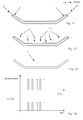
- figure 14 shows the relationship between the intermittent current and the displacement of the strands 4.
- the conductor 2 can also be immersed in an external magnetic field.
- the flexibility can be improved, because the external magnetic field can have the same or opposite polarity as the magnetic field generated by the strands 4 (i.e. by the conductor 2) or is can be extinguished. Naturally, the same effect can be achieved by changing the current of the current 12 (to change the polarity of the magnetic field of the conductor 2 and/or strands 4).
- reference 14 indicates the displacement generated by the interaction with the external magnetic field.
- figure 15 shows an example of the relationship between the intermittent current, the displacement of the strands 4 and/or conductor 2 and the external magnetic field.
- the conductor 2 can also at least partially face one or more ferromagnetic elements 15.
- the effect is the one already described before, because the ferromagnetic element generates attraction between the strands 4 (and thus conductor 2) and the ferromagnetic material 15 itself when the intermittent current 12 passes through the conductor 2, and no attraction when no intermittent current 12 passes through the conductor 2.
- the amplitude and/or frequency and/or shape (waveform) of the intermittent current 12 is preferably regulated; this lets the vibration of the strands 4 and conductor 2 be regulated.
- the intermittent current 12 can be regulated such that it has a frequency corresponding to a resonance frequency for the conductor 2 or at least a strand 4.
- the resonance frequency need not necessarily be the first resonance frequency, but is can also be a subsequent resonance frequency to improve impregnation of specific parts of the conductor 2 and/or strands 4.
- the resonance frequency of the conductor 2 and/or bars 4 can vary over time, for example because of changes in working conditions.
- a steady-matched resonance technique can be used.
- the steady matched resonance technique allows a matching of the current 12 with the resonance frequencies by feedback of signals; this allows a reduction of the dissipation (excessive heat generation in the conductors) and an increase of the vibration amplitude.
- the external magnetic field and/or the magnetic field generated by the conductor 2 can have a variable polarity and/or amplitude over the conductor length and/or over time. This can help impregnation because it allows large flexibility of the intensity and application zones of the forces applied to the conductor 2.
- the external magnetic field is preferably generated by at least a magnet 16; in different examples:
- the magnet or magnets 16 can either be a permanent magnet or an electric magnet; naturally also combinations of permanent and electric magnets are possible.
- each of them can work as an electric magnet for the adjacent conductors.
- the ferromagnetic element When the ferromagnetic element is provided, it can:
- the resonance between the strands and the resonance alongside the stator bar due to mutual interaction with an external field (macro resonance) allow a faster and better impregnation than in traditional methods and systems.
Landscapes
- Engineering & Computer Science (AREA)
- Manufacturing & Machinery (AREA)
- Power Engineering (AREA)
- Manufacture Of Motors, Generators (AREA)
Priority Applications (1)
| Application Number | Priority Date | Filing Date | Title |
|---|---|---|---|
| EP12151940.9A EP2618340A1 (fr) | 2012-01-20 | 2012-01-20 | Procédé d'imprégnation d'un matériau isolant appliqué à un conducteur avec une résine |
Applications Claiming Priority (1)
| Application Number | Priority Date | Filing Date | Title |
|---|---|---|---|
| EP12151940.9A EP2618340A1 (fr) | 2012-01-20 | 2012-01-20 | Procédé d'imprégnation d'un matériau isolant appliqué à un conducteur avec une résine |
Publications (1)
| Publication Number | Publication Date |
|---|---|
| EP2618340A1 true EP2618340A1 (fr) | 2013-07-24 |
Family
ID=45531770
Family Applications (1)
| Application Number | Title | Priority Date | Filing Date |
|---|---|---|---|
| EP12151940.9A Withdrawn EP2618340A1 (fr) | 2012-01-20 | 2012-01-20 | Procédé d'imprégnation d'un matériau isolant appliqué à un conducteur avec une résine |
Country Status (1)
| Country | Link |
|---|---|
| EP (1) | EP2618340A1 (fr) |
Cited By (1)
| Publication number | Priority date | Publication date | Assignee | Title |
|---|---|---|---|---|
| CN104795138A (zh) * | 2015-05-13 | 2015-07-22 | 江苏句容联合铜材有限公司 | 一种丝包换位导线 |
Citations (2)
| Publication number | Priority date | Publication date | Assignee | Title |
|---|---|---|---|---|
| DD139811A2 (de) * | 1974-10-18 | 1980-01-23 | Karl H Junge | Verfahren zur herstellung von gegenstaenden aus faserverstaerkten werkstoffen |
| US4418241A (en) * | 1981-02-25 | 1983-11-29 | Mitsubishi Denki Kabushiki Kaisha | Insulated coil |
-
2012
- 2012-01-20 EP EP12151940.9A patent/EP2618340A1/fr not_active Withdrawn
Patent Citations (2)
| Publication number | Priority date | Publication date | Assignee | Title |
|---|---|---|---|---|
| DD139811A2 (de) * | 1974-10-18 | 1980-01-23 | Karl H Junge | Verfahren zur herstellung von gegenstaenden aus faserverstaerkten werkstoffen |
| US4418241A (en) * | 1981-02-25 | 1983-11-29 | Mitsubishi Denki Kabushiki Kaisha | Insulated coil |
Cited By (1)
| Publication number | Priority date | Publication date | Assignee | Title |
|---|---|---|---|---|
| CN104795138A (zh) * | 2015-05-13 | 2015-07-22 | 江苏句容联合铜材有限公司 | 一种丝包换位导线 |
Similar Documents
| Publication | Publication Date | Title |
|---|---|---|
| CN1112753C (zh) | 电机元件 | |
| US7913375B2 (en) | Method for making electrical windings for electrical machines and winding obtained by said method | |
| US10778054B2 (en) | Electric drive motor | |
| RU2673462C1 (ru) | Самоклеящееся закрывающее паз устройство для электрической машины | |
| CN105322682B (zh) | 用于旋转电机的定子 | |
| US20150288230A1 (en) | Stator or rotor | |
| US20200358330A1 (en) | Slot liner thermal conductivity for electric motors | |
| DE102009021703A1 (de) | Verbesserte Axialflussmaschine | |
| US11139703B2 (en) | Coil winding arrangement | |
| CN106537739A (zh) | 电动机 | |
| CN105305683B (zh) | 用于电机的转子 | |
| CN105391215B (zh) | 绕组装置以及用于制造绕组装置的方法 | |
| US20150091404A1 (en) | Rotor for rotating electric machine, rotating electric machine, and magnetizing apparatus for rotating electric machine | |
| EP2618340A1 (fr) | Procédé d'imprégnation d'un matériau isolant appliqué à un conducteur avec une résine | |
| KR100520548B1 (ko) | 슬롯레스 무브러시 직류 전동기의 전기자 코일 조립구조 | |
| US3504153A (en) | Method of spark machining stator or rotor having lamination simulating characteristics | |
| JP2017093034A (ja) | 回転電機及び回転電機の製造方法 | |
| WO2016101983A1 (fr) | Stator segmenté et son procédé de fabrication | |
| CN106130203B (zh) | 定子及具有其的电机 | |
| CN204316301U (zh) | 导电材料的磁力作用装置 | |
| US20180166963A1 (en) | Transverse flux linear motor | |
| JP6165836B2 (ja) | 回転機 | |
| CN205070648U (zh) | 塑封定子及其绝缘框架、塑封电机 | |
| RU221442U1 (ru) | Статор электрической машины | |
| RU180124U1 (ru) | Статор высокочастотной электрической машины |
Legal Events
| Date | Code | Title | Description |
|---|---|---|---|
| PUAI | Public reference made under article 153(3) epc to a published international application that has entered the european phase |
Free format text: ORIGINAL CODE: 0009012 |
|
| AK | Designated contracting states |
Kind code of ref document: A1 Designated state(s): AL AT BE BG CH CY CZ DE DK EE ES FI FR GB GR HR HU IE IS IT LI LT LU LV MC MK MT NL NO PL PT RO RS SE SI SK SM TR |
|
| AX | Request for extension of the european patent |
Extension state: BA ME |
|
| 17P | Request for examination filed |
Effective date: 20130925 |
|
| RBV | Designated contracting states (corrected) |
Designated state(s): AL AT BE BG CH CY CZ DE DK EE ES FI FR GB GR HR HU IE IS IT LI LT LU LV MC MK MT NL NO PL PT RO RS SE SI SK SM TR |
|
| STAA | Information on the status of an ep patent application or granted ep patent |
Free format text: STATUS: THE APPLICATION HAS BEEN WITHDRAWN |
|
| 18W | Application withdrawn |
Effective date: 20131030 |