EP2622016B1 - Ventilation à récupération d'énergie avec membrane laminée comprenant un copolymère bloc sulfoné - Google Patents
Ventilation à récupération d'énergie avec membrane laminée comprenant un copolymère bloc sulfoné Download PDFInfo
- Publication number
- EP2622016B1 EP2622016B1 EP11833023.2A EP11833023A EP2622016B1 EP 2622016 B1 EP2622016 B1 EP 2622016B1 EP 11833023 A EP11833023 A EP 11833023A EP 2622016 B1 EP2622016 B1 EP 2622016B1
- Authority
- EP
- European Patent Office
- Prior art keywords
- block
- polymer
- membrane
- sulfonated
- sulfonation
- Prior art date
- Legal status (The legal status is an assumption and is not a legal conclusion. Google has not performed a legal analysis and makes no representation as to the accuracy of the status listed.)
- Active
Links
Images


Classifications
-
- B—PERFORMING OPERATIONS; TRANSPORTING
- B01—PHYSICAL OR CHEMICAL PROCESSES OR APPARATUS IN GENERAL
- B01D—SEPARATION
- B01D53/00—Separation of gases or vapours; Recovering vapours of volatile solvents from gases; Chemical or biological purification of waste gases, e.g. engine exhaust gases, smoke, fumes, flue gases, aerosols
- B01D53/22—Separation of gases or vapours; Recovering vapours of volatile solvents from gases; Chemical or biological purification of waste gases, e.g. engine exhaust gases, smoke, fumes, flue gases, aerosols by diffusion
- B01D53/228—Separation of gases or vapours; Recovering vapours of volatile solvents from gases; Chemical or biological purification of waste gases, e.g. engine exhaust gases, smoke, fumes, flue gases, aerosols by diffusion characterised by specific membranes
-
- C—CHEMISTRY; METALLURGY
- C08—ORGANIC MACROMOLECULAR COMPOUNDS; THEIR PREPARATION OR CHEMICAL WORKING-UP; COMPOSITIONS BASED THEREON
- C08L—COMPOSITIONS OF MACROMOLECULAR COMPOUNDS
- C08L53/00—Compositions of block copolymers containing at least one sequence of a polymer obtained by reactions only involving carbon-to-carbon unsaturated bonds; Compositions of derivatives of such polymers
-
- F—MECHANICAL ENGINEERING; LIGHTING; HEATING; WEAPONS; BLASTING
- F28—HEAT EXCHANGE IN GENERAL
- F28D—HEAT-EXCHANGE APPARATUS, NOT PROVIDED FOR IN ANOTHER SUBCLASS, IN WHICH THE HEAT-EXCHANGE MEDIA DO NOT COME INTO DIRECT CONTACT
- F28D9/00—Heat-exchange apparatus having stationary plate-like or laminated conduit assemblies for both heat-exchange media, the media being in contact with different sides of a conduit wall
- F28D9/0025—Heat-exchange apparatus having stationary plate-like or laminated conduit assemblies for both heat-exchange media, the media being in contact with different sides of a conduit wall the conduits being formed by zig-zag bend plates
-
- B—PERFORMING OPERATIONS; TRANSPORTING
- B01—PHYSICAL OR CHEMICAL PROCESSES OR APPARATUS IN GENERAL
- B01D—SEPARATION
- B01D67/00—Processes specially adapted for manufacturing semi-permeable membranes for separation processes or apparatus
- B01D67/0002—Organic membrane manufacture
-
- B—PERFORMING OPERATIONS; TRANSPORTING
- B01—PHYSICAL OR CHEMICAL PROCESSES OR APPARATUS IN GENERAL
- B01D—SEPARATION
- B01D69/00—Semi-permeable membranes for separation processes or apparatus characterised by their form, structure or properties; Manufacturing processes specially adapted therefor
- B01D69/12—Composite membranes; Ultra-thin membranes
- B01D69/1213—Laminated layers
-
- B—PERFORMING OPERATIONS; TRANSPORTING
- B01—PHYSICAL OR CHEMICAL PROCESSES OR APPARATUS IN GENERAL
- B01D—SEPARATION
- B01D69/00—Semi-permeable membranes for separation processes or apparatus characterised by their form, structure or properties; Manufacturing processes specially adapted therefor
- B01D69/12—Composite membranes; Ultra-thin membranes
- B01D69/122—Separate manufacturing of ultra-thin membranes
-
- B—PERFORMING OPERATIONS; TRANSPORTING
- B01—PHYSICAL OR CHEMICAL PROCESSES OR APPARATUS IN GENERAL
- B01D—SEPARATION
- B01D71/00—Semi-permeable membranes for separation processes or apparatus characterised by the material; Manufacturing processes specially adapted therefor
- B01D71/06—Organic material
- B01D71/26—Polyalkenes
- B01D71/261—Polyethylene
-
- B—PERFORMING OPERATIONS; TRANSPORTING
- B01—PHYSICAL OR CHEMICAL PROCESSES OR APPARATUS IN GENERAL
- B01D—SEPARATION
- B01D71/00—Semi-permeable membranes for separation processes or apparatus characterised by the material; Manufacturing processes specially adapted therefor
- B01D71/06—Organic material
- B01D71/28—Polymers of vinyl aromatic compounds
- B01D71/281—Polystyrene
-
- B—PERFORMING OPERATIONS; TRANSPORTING
- B01—PHYSICAL OR CHEMICAL PROCESSES OR APPARATUS IN GENERAL
- B01D—SEPARATION
- B01D71/00—Semi-permeable membranes for separation processes or apparatus characterised by the material; Manufacturing processes specially adapted therefor
- B01D71/06—Organic material
- B01D71/76—Macromolecular material not specifically provided for in a single one of groups B01D71/08 - B01D71/74
- B01D71/80—Block polymers
-
- B—PERFORMING OPERATIONS; TRANSPORTING
- B01—PHYSICAL OR CHEMICAL PROCESSES OR APPARATUS IN GENERAL
- B01D—SEPARATION
- B01D71/00—Semi-permeable membranes for separation processes or apparatus characterised by the material; Manufacturing processes specially adapted therefor
- B01D71/06—Organic material
- B01D71/76—Macromolecular material not specifically provided for in a single one of groups B01D71/08 - B01D71/74
- B01D71/82—Macromolecular material not specifically provided for in a single one of groups B01D71/08 - B01D71/74 characterised by the presence of specified groups, e.g. introduced by chemical after-treatment
-
- B—PERFORMING OPERATIONS; TRANSPORTING
- B01—PHYSICAL OR CHEMICAL PROCESSES OR APPARATUS IN GENERAL
- B01J—CHEMICAL OR PHYSICAL PROCESSES, e.g. CATALYSIS OR COLLOID CHEMISTRY; THEIR RELEVANT APPARATUS
- B01J19/00—Chemical, physical or physico-chemical processes in general; Their relevant apparatus
- B01J19/30—Loose or shaped packing elements, e.g. Raschig rings or Berl saddles, for pouring into the apparatus for mass or heat transfer
-
- B—PERFORMING OPERATIONS; TRANSPORTING
- B32—LAYERED PRODUCTS
- B32B—LAYERED PRODUCTS, i.e. PRODUCTS BUILT-UP OF STRATA OF FLAT OR NON-FLAT, e.g. CELLULAR OR HONEYCOMB, FORM
- B32B27/00—Layered products comprising a layer of synthetic resin
-
- B—PERFORMING OPERATIONS; TRANSPORTING
- B32—LAYERED PRODUCTS
- B32B—LAYERED PRODUCTS, i.e. PRODUCTS BUILT-UP OF STRATA OF FLAT OR NON-FLAT, e.g. CELLULAR OR HONEYCOMB, FORM
- B32B27/00—Layered products comprising a layer of synthetic resin
- B32B27/12—Layered products comprising a layer of synthetic resin next to a fibrous or filamentary layer
-
- B—PERFORMING OPERATIONS; TRANSPORTING
- B32—LAYERED PRODUCTS
- B32B—LAYERED PRODUCTS, i.e. PRODUCTS BUILT-UP OF STRATA OF FLAT OR NON-FLAT, e.g. CELLULAR OR HONEYCOMB, FORM
- B32B27/00—Layered products comprising a layer of synthetic resin
- B32B27/28—Layered products comprising a layer of synthetic resin comprising synthetic resins not wholly covered by any one of the sub-groups B32B27/30 - B32B27/42
-
- B—PERFORMING OPERATIONS; TRANSPORTING
- B32—LAYERED PRODUCTS
- B32B—LAYERED PRODUCTS, i.e. PRODUCTS BUILT-UP OF STRATA OF FLAT OR NON-FLAT, e.g. CELLULAR OR HONEYCOMB, FORM
- B32B27/00—Layered products comprising a layer of synthetic resin
- B32B27/30—Layered products comprising a layer of synthetic resin comprising vinyl (co)polymers; comprising acrylic (co)polymers
- B32B27/302—Layered products comprising a layer of synthetic resin comprising vinyl (co)polymers; comprising acrylic (co)polymers comprising aromatic vinyl (co)polymers, e.g. styrenic (co)polymers
-
- B—PERFORMING OPERATIONS; TRANSPORTING
- B32—LAYERED PRODUCTS
- B32B—LAYERED PRODUCTS, i.e. PRODUCTS BUILT-UP OF STRATA OF FLAT OR NON-FLAT, e.g. CELLULAR OR HONEYCOMB, FORM
- B32B3/00—Layered products comprising a layer with external or internal discontinuities or unevennesses, or a layer of non-planar shape; Layered products comprising a layer having particular features of form
- B32B3/02—Layered products comprising a layer with external or internal discontinuities or unevennesses, or a layer of non-planar shape; Layered products comprising a layer having particular features of form characterised by features of form at particular places, e.g. in edge regions
- B32B3/08—Layered products comprising a layer with external or internal discontinuities or unevennesses, or a layer of non-planar shape; Layered products comprising a layer having particular features of form characterised by features of form at particular places, e.g. in edge regions characterised by added members at particular parts
- B32B3/085—Layered products comprising a layer with external or internal discontinuities or unevennesses, or a layer of non-planar shape; Layered products comprising a layer having particular features of form characterised by features of form at particular places, e.g. in edge regions characterised by added members at particular parts spaced apart pieces on the surface of a layer
-
- B—PERFORMING OPERATIONS; TRANSPORTING
- B32—LAYERED PRODUCTS
- B32B—LAYERED PRODUCTS, i.e. PRODUCTS BUILT-UP OF STRATA OF FLAT OR NON-FLAT, e.g. CELLULAR OR HONEYCOMB, FORM
- B32B3/00—Layered products comprising a layer with external or internal discontinuities or unevennesses, or a layer of non-planar shape; Layered products comprising a layer having particular features of form
- B32B3/26—Layered products comprising a layer with external or internal discontinuities or unevennesses, or a layer of non-planar shape; Layered products comprising a layer having particular features of form characterised by a particular shape of the outline of the cross-section of a continuous layer; characterised by a layer with cavities or internal voids ; characterised by an apertured layer
- B32B3/28—Layered products comprising a layer with external or internal discontinuities or unevennesses, or a layer of non-planar shape; Layered products comprising a layer having particular features of form characterised by a particular shape of the outline of the cross-section of a continuous layer; characterised by a layer with cavities or internal voids ; characterised by an apertured layer characterised by a layer comprising a deformed thin sheet, i.e. the layer having its entire thickness deformed out of the plane, e.g. corrugated, crumpled
-
- C—CHEMISTRY; METALLURGY
- C08—ORGANIC MACROMOLECULAR COMPOUNDS; THEIR PREPARATION OR CHEMICAL WORKING-UP; COMPOSITIONS BASED THEREON
- C08F—MACROMOLECULAR COMPOUNDS OBTAINED BY REACTIONS ONLY INVOLVING CARBON-TO-CARBON UNSATURATED BONDS
- C08F297/00—Macromolecular compounds obtained by successively polymerising different monomer systems using a catalyst of the ionic or coordination type without deactivating the intermediate polymer
- C08F297/02—Macromolecular compounds obtained by successively polymerising different monomer systems using a catalyst of the ionic or coordination type without deactivating the intermediate polymer using a catalyst of the anionic type
- C08F297/04—Macromolecular compounds obtained by successively polymerising different monomer systems using a catalyst of the ionic or coordination type without deactivating the intermediate polymer using a catalyst of the anionic type polymerising vinyl aromatic monomers and conjugated dienes
- C08F297/046—Macromolecular compounds obtained by successively polymerising different monomer systems using a catalyst of the ionic or coordination type without deactivating the intermediate polymer using a catalyst of the anionic type polymerising vinyl aromatic monomers and conjugated dienes polymerising vinyl aromatic monomers and isoprene, optionally with other conjugated dienes
-
- C—CHEMISTRY; METALLURGY
- C08—ORGANIC MACROMOLECULAR COMPOUNDS; THEIR PREPARATION OR CHEMICAL WORKING-UP; COMPOSITIONS BASED THEREON
- C08F—MACROMOLECULAR COMPOUNDS OBTAINED BY REACTIONS ONLY INVOLVING CARBON-TO-CARBON UNSATURATED BONDS
- C08F8/00—Chemical modification by after-treatment
- C08F8/04—Reduction, e.g. hydrogenation
-
- C—CHEMISTRY; METALLURGY
- C08—ORGANIC MACROMOLECULAR COMPOUNDS; THEIR PREPARATION OR CHEMICAL WORKING-UP; COMPOSITIONS BASED THEREON
- C08F—MACROMOLECULAR COMPOUNDS OBTAINED BY REACTIONS ONLY INVOLVING CARBON-TO-CARBON UNSATURATED BONDS
- C08F8/00—Chemical modification by after-treatment
- C08F8/34—Introducing sulfur atoms or sulfur-containing groups
- C08F8/36—Sulfonation; Sulfation
-
- F—MECHANICAL ENGINEERING; LIGHTING; HEATING; WEAPONS; BLASTING
- F24—HEATING; RANGES; VENTILATING
- F24F—AIR-CONDITIONING; AIR-HUMIDIFICATION; VENTILATION; USE OF AIR CURRENTS FOR SCREENING
- F24F12/00—Use of energy recovery systems in air conditioning, ventilation or screening
- F24F12/001—Use of energy recovery systems in air conditioning, ventilation or screening with heat-exchange between supplied and exhausted air
- F24F12/006—Use of energy recovery systems in air conditioning, ventilation or screening with heat-exchange between supplied and exhausted air using an air-to-air heat exchanger
-
- F—MECHANICAL ENGINEERING; LIGHTING; HEATING; WEAPONS; BLASTING
- F24—HEATING; RANGES; VENTILATING
- F24F—AIR-CONDITIONING; AIR-HUMIDIFICATION; VENTILATION; USE OF AIR CURRENTS FOR SCREENING
- F24F7/00—Ventilation
-
- F—MECHANICAL ENGINEERING; LIGHTING; HEATING; WEAPONS; BLASTING
- F28—HEAT EXCHANGE IN GENERAL
- F28D—HEAT-EXCHANGE APPARATUS, NOT PROVIDED FOR IN ANOTHER SUBCLASS, IN WHICH THE HEAT-EXCHANGE MEDIA DO NOT COME INTO DIRECT CONTACT
- F28D21/00—Heat-exchange apparatus not covered by any of the groups F28D1/00 - F28D20/00
- F28D21/0015—Heat and mass exchangers, e.g. with permeable walls
-
- F—MECHANICAL ENGINEERING; LIGHTING; HEATING; WEAPONS; BLASTING
- F28—HEAT EXCHANGE IN GENERAL
- F28D—HEAT-EXCHANGE APPARATUS, NOT PROVIDED FOR IN ANOTHER SUBCLASS, IN WHICH THE HEAT-EXCHANGE MEDIA DO NOT COME INTO DIRECT CONTACT
- F28D9/00—Heat-exchange apparatus having stationary plate-like or laminated conduit assemblies for both heat-exchange media, the media being in contact with different sides of a conduit wall
- F28D9/0062—Heat-exchange apparatus having stationary plate-like or laminated conduit assemblies for both heat-exchange media, the media being in contact with different sides of a conduit wall the conduits for one heat-exchange medium being formed by spaced plates with inserted elements
-
- B—PERFORMING OPERATIONS; TRANSPORTING
- B32—LAYERED PRODUCTS
- B32B—LAYERED PRODUCTS, i.e. PRODUCTS BUILT-UP OF STRATA OF FLAT OR NON-FLAT, e.g. CELLULAR OR HONEYCOMB, FORM
- B32B2250/00—Layers arrangement
- B32B2250/40—Symmetrical or sandwich layers, e.g. ABA, ABCBA, ABCCBA
-
- B—PERFORMING OPERATIONS; TRANSPORTING
- B32—LAYERED PRODUCTS
- B32B—LAYERED PRODUCTS, i.e. PRODUCTS BUILT-UP OF STRATA OF FLAT OR NON-FLAT, e.g. CELLULAR OR HONEYCOMB, FORM
- B32B2250/00—Layers arrangement
- B32B2250/42—Alternating layers, e.g. ABAB(C), AABBAABB(C)
-
- B—PERFORMING OPERATIONS; TRANSPORTING
- B32—LAYERED PRODUCTS
- B32B—LAYERED PRODUCTS, i.e. PRODUCTS BUILT-UP OF STRATA OF FLAT OR NON-FLAT, e.g. CELLULAR OR HONEYCOMB, FORM
- B32B2262/00—Composition or structural features of fibres which form a fibrous or filamentary layer or are present as additives
- B32B2262/02—Synthetic macromolecular fibres
- B32B2262/0276—Polyester fibres
- B32B2262/0284—Polyethylene terephthalate [PET] or polybutylene terephthalate [PBT]
-
- B—PERFORMING OPERATIONS; TRANSPORTING
- B32—LAYERED PRODUCTS
- B32B—LAYERED PRODUCTS, i.e. PRODUCTS BUILT-UP OF STRATA OF FLAT OR NON-FLAT, e.g. CELLULAR OR HONEYCOMB, FORM
- B32B2270/00—Resin or rubber layer containing a blend of at least two different polymers
-
- B—PERFORMING OPERATIONS; TRANSPORTING
- B32—LAYERED PRODUCTS
- B32B—LAYERED PRODUCTS, i.e. PRODUCTS BUILT-UP OF STRATA OF FLAT OR NON-FLAT, e.g. CELLULAR OR HONEYCOMB, FORM
- B32B2307/00—Properties of the layers or laminate
- B32B2307/70—Other properties
- B32B2307/724—Permeability to gases, adsorption
- B32B2307/7242—Non-permeable
-
- C—CHEMISTRY; METALLURGY
- C08—ORGANIC MACROMOLECULAR COMPOUNDS; THEIR PREPARATION OR CHEMICAL WORKING-UP; COMPOSITIONS BASED THEREON
- C08F—MACROMOLECULAR COMPOUNDS OBTAINED BY REACTIONS ONLY INVOLVING CARBON-TO-CARBON UNSATURATED BONDS
- C08F2810/00—Chemical modification of a polymer
- C08F2810/50—Chemical modification of a polymer wherein the polymer is a copolymer and the modification is taking place only on one or more of the monomers present in minority
-
- F—MECHANICAL ENGINEERING; LIGHTING; HEATING; WEAPONS; BLASTING
- F24—HEATING; RANGES; VENTILATING
- F24F—AIR-CONDITIONING; AIR-HUMIDIFICATION; VENTILATION; USE OF AIR CURRENTS FOR SCREENING
- F24F3/00—Air-conditioning systems in which conditioned primary air is supplied from one or more central stations to distributing units in the rooms or spaces where it may receive secondary treatment; Apparatus specially designed for such systems
- F24F3/12—Air-conditioning systems in which conditioned primary air is supplied from one or more central stations to distributing units in the rooms or spaces where it may receive secondary treatment; Apparatus specially designed for such systems characterised by the treatment of the air otherwise than by heating and cooling
- F24F3/14—Air-conditioning systems in which conditioned primary air is supplied from one or more central stations to distributing units in the rooms or spaces where it may receive secondary treatment; Apparatus specially designed for such systems characterised by the treatment of the air otherwise than by heating and cooling by humidification; by dehumidification
- F24F2003/1435—Air-conditioning systems in which conditioned primary air is supplied from one or more central stations to distributing units in the rooms or spaces where it may receive secondary treatment; Apparatus specially designed for such systems characterised by the treatment of the air otherwise than by heating and cooling by humidification; by dehumidification comprising semi-permeable membrane
-
- Y—GENERAL TAGGING OF NEW TECHNOLOGICAL DEVELOPMENTS; GENERAL TAGGING OF CROSS-SECTIONAL TECHNOLOGIES SPANNING OVER SEVERAL SECTIONS OF THE IPC; TECHNICAL SUBJECTS COVERED BY FORMER USPC CROSS-REFERENCE ART COLLECTIONS [XRACs] AND DIGESTS
- Y02—TECHNOLOGIES OR APPLICATIONS FOR MITIGATION OR ADAPTATION AGAINST CLIMATE CHANGE
- Y02B—CLIMATE CHANGE MITIGATION TECHNOLOGIES RELATED TO BUILDINGS, e.g. HOUSING, HOUSE APPLIANCES OR RELATED END-USER APPLICATIONS
- Y02B30/00—Energy efficient heating, ventilation or air conditioning [HVAC]
- Y02B30/56—Heat recovery units
-
- Y—GENERAL TAGGING OF NEW TECHNOLOGICAL DEVELOPMENTS; GENERAL TAGGING OF CROSS-SECTIONAL TECHNOLOGIES SPANNING OVER SEVERAL SECTIONS OF THE IPC; TECHNICAL SUBJECTS COVERED BY FORMER USPC CROSS-REFERENCE ART COLLECTIONS [XRACs] AND DIGESTS
- Y02—TECHNOLOGIES OR APPLICATIONS FOR MITIGATION OR ADAPTATION AGAINST CLIMATE CHANGE
- Y02P—CLIMATE CHANGE MITIGATION TECHNOLOGIES IN THE PRODUCTION OR PROCESSING OF GOODS
- Y02P20/00—Technologies relating to chemical industry
- Y02P20/10—Process efficiency
-
- Y—GENERAL TAGGING OF NEW TECHNOLOGICAL DEVELOPMENTS; GENERAL TAGGING OF CROSS-SECTIONAL TECHNOLOGIES SPANNING OVER SEVERAL SECTIONS OF THE IPC; TECHNICAL SUBJECTS COVERED BY FORMER USPC CROSS-REFERENCE ART COLLECTIONS [XRACs] AND DIGESTS
- Y02—TECHNOLOGIES OR APPLICATIONS FOR MITIGATION OR ADAPTATION AGAINST CLIMATE CHANGE
- Y02P—CLIMATE CHANGE MITIGATION TECHNOLOGIES IN THE PRODUCTION OR PROCESSING OF GOODS
- Y02P20/00—Technologies relating to chemical industry
- Y02P20/50—Improvements relating to the production of bulk chemicals
Definitions
- the present disclosure relates to a membrane for use in an energy recovery ventilation core unit.
- the present disclosure relates to a membrane made up of a microporous substrate laminated with a sulfonated block copolymer having at least two polymer end blocks that contain little or no sulfonic acid or sulfonate functionality and at least one polymer interior block which contains an effective amount of sulfonic acid or sulfonate functionality.
- the present disclosure further relates to an energy recovery ventilation core unit which employs such membranes and to the energy recovery ventilation system having such a core unit.
- heating and cooling systems are employed for temperature control of buildings and various housing. Often fresh air will be ushered from outside of the building or house while exhaust air from within will be returned outdoors. Generally, a large amount of energy is expended in such cooling and heating systems. One way to conserve the cost for this expenditure of energy is by exchanging some of the heat and moisture between the air streams as they are entering and exiting the structure.
- ERV energy recovery ventilation
- ERV systems are usually employed in conjunction with a heating and/or cooling system, and are made up of a device having an ERV core unit.
- the core unit is generally comprised of various stacked membranes separated by some type of barrier.
- the intake and exhaust air streams are transported to the core unit and made to pass by one another without intermixture on each side of the stacked plates.
- Sensible heat exchange is generally simpler to accomplish since a thin layer barrier may transfer heat rather easily.
- latent heat transfer is affected by the change in humidity between the air streams. Accordingly, what is needed therefore is a system that allows for both the efficient exchange of both sensible and latent heat of the various intake and exhaust air flows.
- US 2006/0113070 A1 discloses a heat exchanger of a ventilating system that includes heat exchange plates having first air passage through which indoor air being discharged to outside of a building passes and a second air passage through which outdoor air of the building passes which are sequentially formed; first corrugation plates attached to the first air passage, and second corrugation plates attached to the second air passage
- the heat exchange plates are made of a paper material with numerous fine holes that are able to generate a capillary phenomenon and loess which radiates far infrared ray. Heat exchange and moisture exchange between the indoor air and the outdoor air are performed simultaneously, and a cleaning function of removing a harmful material contained in outdoor air can be carried out.
- US 2007/0021569 A1 discloses a block copolymer comprising at least two polymer end blocks A and at least one polymer interior block B wherein each A block is a polymer block resistant to sulfonation and each B block is a polymer block susceptible to sulfonation, and wherein said A and B blocks do not contain any significant levels of olefinic unsaturation.
- the block copolymers are used in protective clothing and breathable fabric applications where the membranes, coated fabrics, and fabric laminates could provide a barrier of protection from various environmental elements.
- the fabrics are made by laminating a film of the sulfonated polymer between a liner fabric and a shell fabric.
- US 4,207,364 discloses a tubular article comprising, in combination, an inner tube and a coaxial outer tube, where the inner tube comprises an elastomeric material and is in a radially expanded condition.
- the outer tube comprises a glassy or crystalline linear polymeric material.
- the inner radially expanded tube is bonded to and maintained in its radially expanded condition by the outer tube.
- US 5,840,387 discloses sulfonated multiblock copolymers for use in non-thrombogenic coatings, e.g., for medical devices, and for promoting cell growth, differentiation, or production of normal cell products.
- the sulfonated copolymers are also useful for administration of therapeutic agents.
- US 5,239,010 discloses a thermoplastic polymer having excellent mechanical properties at both room and elevated temperatures.
- the polymer is obtained by reacting an acyl sulfate with a block copolymer composed of at least one conjugated diene block and one alkenyl arene block.
- the block copolymer is first selectively hydrogenated and thereafter modified by grafting sulfonic acid functional groups primarily in the alkenyl arene blocks.
- the mechanical properties may be varied and controlled by varying the degree of functionalization (amount of sulfonation), and the degree of neutralization of the sulfonic acid groups to metal sulfonate salts.
- US 2009/0280255 A1 discloses sulfonated block copolymers and the use of a solution of the sulfonated block copolymer for preparing various membranes and other articles, including coatings on microporous membranes, ePTFE and fibrous mats, and for laminating the copolymer film onto fabrics.
- US 6,841,601 B2 discloses use of an organic-inorganic hybrid for the construction of humidity exchange cells by bonding the polymer to a reinforcing substrate by hot roll laminating instead of coating.
- the organic-inorganic hybrid is derived from combining at least one inorganic alkoxide and at least one sulfonated styrene polymer comprising sulfonated styrene and olefin units.
- Latent heat is effected in large proportion by the change in humidity of the incoming and exiting air. Accordingly, latent heat transfer becomes in large degree a function of the ERV membrane's ability to transport water vapor between the two aiflow streams.
- ERV system for the improved sensible and latent heat exchange between inflow and outflow air streams. This has been achieved by a membrane disclosed herein made up of a microporous substrate with a laminate having a sulfonated block copolymer.
- the sulfonated block copolymer has high water vapor transport rates, thus facilitating efficient latent heat exchange.
- the present invention relates to a laminate membrane in accordance with claim 1 and to an energy recovery system in accordance with claim 11.
- the membrane can include a spacer element interposed between itself and a second membrane, the spacer and the membrane forming a layer in an ERV core unit.
- the core unit has a plurality of said layers stacked one upon the other.
- the microporous substrate is a fibrous woven or non-woven material.
- the microporous substrate is selected from the group consisting of carbon, fiberglass, polyester, polyethylene, polyethylene terephthalate, cellulose, cellulose nitrate, cellulose acetate, nylon, polytetrafluoroethylene.
- each A block comprises one or more segments selected from polymerized (i) para-substituted styrene monomers, (ii) ethylene, (iii) alpha olefins of 3 to 18 carbon atoms; (iv) 1,3-cyclodiene monomers, (v) acrylic esters, (vi) methacrylic esters, and (vii) mixtures thereof.
- each B block comprises segments of one or more vinyl aromatic monomers selected from polymerized (i) unsubstituted styrene monomers, (ii) ortho-substituted styrene monomers, (iii) meta-substituted styrene monomers, (iv) alpha-methylstyrene, (v) 1,1-diphenylethylene, (vi) 1,2-diphenylethylene and (vii) mixtures thereof.
- vinyl aromatic monomers selected from polymerized (i) unsubstituted styrene monomers, (ii) ortho-substituted styrene monomers, (iii) meta-substituted styrene monomers, (iv) alpha-methylstyrene, (v) 1,1-diphenylethylene, (vi) 1,2-diphenylethylene and (vii) mixtures thereof.
- the sulfonated block copolymer has the general configuration A-B-A, A-B-A-B-A, (A-B-A) n X, (A-B) n X, A-D-B-D-A, A-B-D-B-A, (A-D-B) n X, (A-B-D) n X or mixtures thereof, where n is an integer from 2 to about 30, and X is a coupling agent residue and wherein each D block is a polymer block resistant to sulfonation and the plurality of A blocks , B blocks, or D blocks are the same or different.
- each D block is selected from the group consisting of (i) a polymerized or copolymerized conjugated diene from isoprene (ii) a polymerized acrylate monomer, (iii) a silicon polymer, (iv) polymerized isobutylene and (v) mixtures thereof, wherein any segments containing polymerized 1,3-butadiene or isoprene are subsequently hydrogenated
- the passageways of the energy recovery system are made up of two sets of passageways with a first set arranged in a first direction and a second set arranged in a second direction different from said first direction thereby enabling the at least two independent air streams to have a cross-flow pattern.
- the spacer element is metal, fiberglass or plastic.
- the microporous substrate can be fibrous woven or non-woven material.
- the microporous substrate is selected from the group consisting of carbon, fiberglass, polyester, polyethylene, polyethylene terephthalate, cellulose, cellulose nitrate, cellulose acetate, nylon, polytetrafluoroethylene.
- the sulfonated block copolymer is heat laminated on the microporous support substrate.
- the expression “coated” or “coating” means the application or bonding of a polymer in solution or liquid form to a substrate or other material.
- laminate means the application or bonding of a cast polymer membrane or polymer film to a substrate or other material.
- T ° C T ° F ⁇ 32 ⁇ 5 / 9
- ERV systems for the exchange of sensible and latent heat between an intake airflow stream and an exhaust airflow stream.
- ERV systems employ a core unit having a stack of multiple moisture permeable membranes separated by spacers. Both the intake airflow streams as well as the exiting airflow streams are transported to the ERV core unit. In the core unit, the air streams are separated by the membranes in the core unit as they flow past one another. In this way heat and moisture are exchanged between the two air streams.
- FIG. 1 One embodiment of an ERV core unit 1 is shown in Fig. 1 .
- the unit has a housing made up of a top cover 2 and a bottom cover 3 with side supports 4.
- exchange element 5 made up of a plurality of air exchange membranes separated by plurality spacer elements.
- the fresh intake air flow is shown by arrow 8 and furthermore the exhaust air flow is shown by arrow 9.
- Spacer elements 7 are configured to provide channels for airflow between membranes 6.
- the size of such channels may be such as to provide an air gap from about 5 to 30 mm. In the embodiment shown in Fig. 2 , this is done by forming the spacers 7 into a ridged formation. The crests thus form longitudinal apertures along the length of the spacers in one direction, thus permitting flow both above and below the spacer depending on the formation of the ridges.
- Such spacers may be made up of fiberglass, aluminum or plastic. Other materials may similarly be used which provide strength and maintain the membranes separated for permitting and directing airflow. The material should be such that both air and moisture is not permitted to pass through the spacers themselves.
- the spacers are ridged and arranged in a transverse configuration.
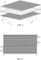
- one set of spacers 7a are arranged so that the air channels are aligned in one longitudinal direction
- a second set of spacers 7b are arranged such that the air channels are aligned in a second longitudinal direction, each set being stacked in alternating fashion.
- fresh intake air 8 may be passed through the spacer air channels in one direction
- the exhaust air 9 is passed through the spacer air channels in a second direction.
- membranes are arranged on either side of the spacer elements 7, heat and moisture can be exchanged through the membrane without intermixture of the different air streams. While Fig. 3 illustrates the spacers 7a and 7b disassembled, Fig. 4 shows this arrangement of spacers stacked one on top of the other as they would be in a core unit (with membranes between each).
- ERV units have cores with ridged spacers are sold for example by Innergytech in their enthalpy heat exchanger units. Additionally, for example US 6,536,514 discloses a ridged spacer with a moisture permeable membranes.
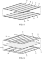
- the spacers may be made up of singular elongate ribs 10 adhered to the surface of membranes 11, which are which extend along the length of the core unit, with each successive layer alternating to form a cross flow pattern.
- the spacers may be made up of a plate 12 which can be laid in between membranes. Such plates may have an outer frame 13, with longitudinal partitions 14 spaced a distance from one another. Such plates may be made up of fiberglass, aluminum or plastic.
- a membrane 6 is placed between plates 12, with plates 12 being stacked in an alternating cross flow pattern.
- the top plate extends in one direction while the lower plate extends in a second direction, which is perpendicular in the illustrative example.
- the partitions 14 form air channels 15 which direct the air streams flowing through the ERV unit. Apertures are placed in the side of the outer frame 13 to allow air flow in to the air channels 15.
- Spacers such as that shown in Figs. 2-6 , may have configurations other than longitudinal, for example, they may be diagonal or jagged, or have other shapes. By adjusting the shape of the partitions the residence time of the air streams in the ERV core can be increased thereby improving heat and moisture exchange. Furthermore, such spacers can be stacked such that the intake and exhaust air streams have cross flows in any direction, for example transversely, right angles, or any non-parallel configuration. Further, parallel configurations can be employed as well if the gases can be prevented from being intermixed as they enter or exit the core.
- the spacers are provided in order to allow membrane surfaces to contact the intake and exhaust air flow streams in a non-parallel direction one on each side of a membrane without intermixture thereof.
- the membranes allow transfer of moisture between the air streams, and thus allowing sensible heat exchange. Accordingly, the ability to more efficiently transfer moisture greatly affects the effectiveness and efficiency of the ERV unit. As disclosed herein, it has been found a surprisingly improved ERV membrane having a polymer film laminated to a substrate for improved water vapor transport between the intake and exhaust gas streams
- the substrate is employed with the membrane to provide mechanical strength while additionally facilitating water vapor transport. Accordingly, it should be made of a porous material to allow moisture to pass through with as little resistance as possible while also providing structural integrity.
- the porous substrate may be those known and used in the art, many of which are commercially available.
- the substrate to be used with the membrane disclosed herein includes porous cellulosic fibrous materials.
- Microporous films may also be used. Materials include, for example, fabrics, polymeric films and fibers, and cellulosic materials (such as paper).
- the substrate may be composed of natural and/or synthetic fibers. Fabrics include wovens, non-wovens, knits and cross-laid fabrics.
- the substrate may be composed of filaments, glass yarns, fiberglass, non-corroding metal fibers (such as nickel fibers), as well as well as carbon fibers.
- Synthetic fibers include polyolefins, polyethylene, polypropylene, and polyesters.
- Exemplary substrates also include polyvinylidene fluoride, polytetrafluoroethylene, nylon, polyethersulfone, polypropylene, polyamide, cellulose, cellulose nitrate, cellulose acetate, cellulose nitrate/acetate polytetrafluoroethylene, Polyethylene Terephthalate (PET), and Polyether ether ketone (PEEK).
- PET Polyethylene Terephthalate
- PEEK Polyether ether ketone
- Additives or coatings may be added to the substrate to improve other properties. Such additives should not interfere with the effectiveness and efficiency of the ERV unit, or introduce any harmful components into the air streams.
- One type of additives is flame retardants which may be employed to inhibit or prevent fire or the spread of fire.
- non-halogen flame retardants may be employed as well as phosphorus containing compounds.
- Halogen flame retardants may include bromine containing retardants.
- Other useful flame retardants known in the art may be used.
- Biocides may also be applied, including fungicides, microbicides and bactericides, for preventing growth of molds, mildew, fungus, bacteria, viruses, and parasites as well as other biological organisms that may be harmful to humans or reduce the efficiency of the ERV unit.
- additives may be added to the substrate to increase its strength, porosity and life, or reduce odor such as anti-oxidants, silica, alumina and zeolites.
- the membrane to be used in the ERV core disclosed herein is a polymeric film layer laminated onto a porous substrate.
- the polymeric film is composed of or includes a sulfonated block copolymer. It has been surprisingly found that the when the sulfonated block copolymer disclosed herein is laminated onto a porous substrate, water vapor transport, and thus latent heat exchange, is significantly improved.
- the sulfonated block copolymers which are used in the polymer film layer include sulfonated block copolymers as described in US 2007/0021569 to Willis et al. .
- the sulfonated block copolymers which include the sulfonated block copolymers as described in US 2007/0021569 may be prepared according to the process of WO 2008/089332 to Dado et al. .
- the block copolymers needed to prepare the sulfonated block copolymers may be made by a number of different processes, including anionic polymerization, moderated anionic polymerization, cationic polymerization, Ziegler-Natta polymerization, and living chain or stable free radical polymerization.
- Anionic polymerization is described below in more detail, and in the referenced documents.
- Moderated anionic polymerization processes for making styrenic block copolymers are disclosed, for example, in US 6,391,981 , US 6,455,651 and US 6,492,469 .
- Cationic polymerization processes for preparing block copolymers are disclosed, for example, in US 6,515,083 and US 4,946,899 .
- styrenic block copolymers can be synthesized by living or stable free radical techniques. Nitroxide mediated polymerization methods are preferred living chain or stable free radical polymerization processes when preparing the precursor polymers.
- the neutralized block copolymers have at least two polymer end or outer blocks A and at least one saturated polymer interior block B wherein each A block is a polymer block which is resistant to sulfonation and each B block is a polymer block which is susceptible to sulfonation.
- Preferred block copolymer structures have the general configuration A-B-A, (A-B)n(A), (A-B-A)n, (A-B-A) n X, (A-B)nX, A-B-D-B-A, A-D-B-D-A, (A-D-B)n(A), (A-B-D)n(A), (A-B-D)nX, (A-D-B)nX or mixtures thereof, where n is an integer from 2 to about 30, X is coupling agent residue and A, B and D are as defined hereinafter.
- Most preferred structures are linear structures such as A-B-A, (A-B)2X, A-B-D-B-A, (A-B-D)2X, A-D-B-D-A, and (A-D-B)2X and radial structures such as (A-B)nX and (A-D-B)nX where n is 3 to 6.
- Such block copolymers are typically made via anionic polymerization, stable free radical polymerization, cationic polymerization or Ziegler-Natta polymerization.
- the block copolymers are made via anionic polymerization. It will be understood by those skilled in the art that in any polymerization, the polymer mixture will include a certain amount of A-B diblock copolymer, in addition to any linear and/or radial polymers. The respective amounts have not been found to be detrimental.
- the A blocks are one or more segments selected from polymerized (i) para-substituted styrene monomers, (ii) ethylene, (iii) alpha olefins of 3 to 18 carbon atoms; (iv) 1,3-cyclodiene monomers, (v) acrylic esters, (vi) methacrylic esters, and (vii) mixtures thereof. If the A segments are polymers of 1,3-cyclodiene or conjugated dienes, the segments will be hydrogenated subsequent to polymerization of the block copolymer and before sulfonation of the block copolymer.
- the para-substituted styrene monomers are selected from para-methylstyrene, para-ethylstyrene, para-n-propylstyrene, para-iso-propylstyrene, para-n-butylstyrene, para-sec-butylstyrene, para-iso-butylstyrene, para-t-butylstyrene, isomers of para-decylstyrene, isomers of para-dodecylstyrene and mixtures of the above monomers.
- Preferred para-substituted styrene monomers are para-t-butylstyrene and para-methylstyrene, with para-t-butylstyrene being most preferred.
- Monomers may be mixtures of monomers, depending on the particular source. It is desired that the overall purity of the para-substituted styrene monomers be at least 90%-wt., preferably at least 95%-wt., and even more preferably at least 98%-wt. of the desired para-substituted styrene monomer.
- the A blocks are polymer segments of ethylene
- the block molecular weight for such ethylene blocks will typically be between about 1,000 and about 60,000.
- the A blocks are polymers of alpha olefins of 3 to 18 carbon atoms
- such polymers are prepared by via a Ziegler-Natta process, as taught in the references in the above-cited review article by G.W. Coates et al.
- the alpha-olefins are propylene, butylene, hexane or octane, with propylene being most preferred.
- the block molecular weight for each of such alpha-olefin blocks typically is between about 1,000 and about 60,000.
- the A blocks are hydrogenated polymers of 1,3-cyclodiene monomers
- such monomers are selected from the group consisting of 1,3-cyclohexadiene, 1,3-cycloheptadiene and 1,3-cyclooctadiene.
- the cyclodiene monomer is 1,3-cyclohexadiene.
- Polymerization of such cyclodiene monomers is disclosed in US 6,699,941 . It will be necessary to hydrogenate the A blocks when using cyclodiene monomers since non-hydrogenated polymerized cyclodiene blocks are susceptible to sulfonation. Accordingly, after synthesis of the A block with 1,3-cyclodiene monomers, the block copolymer will be hydrogenated.
- the A blocks are hydrogenated polymers of conjugated acyclic dienes having a vinyl content less than 35 mol percent prior to hydrogenation
- the conjugated diene is 1,3-butadiene.
- the vinyl content of the polymer prior to hydrogenation be less than 35 mol percent, preferably less than 30 mol percent.
- the vinyl content of the polymer prior to hydrogenation will be less than 25 mol percent, even more preferably less than 20 mol percent, and even less than 15 mol percent with one of the more advantageous vinyl contents of the polymer prior to hydrogenation being less than 10 mol percent.
- the A blocks will have a crystalline structure, similar to that of polyethylene.
- Such A block structures are disclosed in US 3,670,054 and in US 4,107,236 .
- the A blocks may also be polymer segments of acrylic esters or methacrylic esters. Such polymer blocks may be made according to the methods disclosed in US 6,767,976 .
- Specific examples of the methacrylic ester include esters of a primary alcohol and methacrylic acid, such as methyl methacrylate, ethyl methacrylate, propyl methacrylate, n-butyl methacrylate, isobutyl methacrylate, hexyl methacrylate, 2-ethylhexyl methacrylate, dodecyl methacrylate, lauryl methacrylate, methoxyethyl methacrylate, dimethylaminoethyl methacrylate, diethylaminoethyl methacrylate, glycidyl methacrylate, trimethoxysilylpropyl methacrylate, trifluoromethyl methacrylate, trifluoroethyl methacrylate; esters of
- acrylic ester examples include esters of a primary alcohol and acrylic acid, such as methyl acrylate, ethyl acrylate, propyl acrylate, n-butyl acrylate, isobutyl acrylate, hexyl acrylate, 2-ethylhexyl acrylate, dodecyl acrylate, lauryl acrylate, methoxyethyl acrylate, dimethylaminoethyl acrylate, diethylaminoethyl acrylate, glycidyl acrylate, trimethoxysilylpropyl acrylate, trifluoromethyl acrylate, trifluoroethyl acrylate; esters of a secondary alcohol and acrylic acid, such as isopropyl acrylate, cyclohexyl acrylate and isobomyl acrylate; and esters of a tertiary alcohol and acrylic acid, such as tert-butyl acrylate.
- anionic polymerizable monomers may be used together with the (meth)acrylic ester.
- anionic polymerizable monomer examples include methacrylic or acrylic monomers such as trimethylsilyl methacrylate, N-,N-dimethylmethacrylamide, N,N-diisopropylmethacrylamide, N,N-diethylmethacrylamide, N,N-methylethylmethacrylamide, N,N-di-tert-butylmethacrylamide, trimethylsilyl acrylate, N,N-dimethylacrylamide, N,N-di-isopropylacrylamide, N,N-methylethylacrylamide and N,N-di-tert-butylacrylamide.
- a multifunctional anionic polymerizable monomer having in the molecule thereof two or more methacrylic or acrylic structures, such as methacrylic ester structures or acrylic ester structures (for example, ethylene glycol diacrylate, ethylene glycol dimethacrylate, 1,4-butanediol diacrylate, 1,4-butanediol dimethacrylate, 1,6-hexanediol diacrylate, 1,6-hexanediol dimethacrylate, trimethylolpropane triacrylate and trimethylolpropane trimethacrylate).
- methacrylic ester structures for example, ethylene glycol diacrylate, ethylene glycol dimethacrylate, 1,4-butanediol diacrylate, 1,4-butanediol dimethacrylate, 1,6-hexanediol diacrylate, 1,6-hexanediol dimethacrylate, trimethylolpropane triacrylate and
- any copolymerization form selected from random, block, tapered block and the like copolymerization forms may be effected by selecting conditions such as a combination of the monomers and the timing of adding the monomers to the polymerization system (for example, simultaneous addition of two or more monomers, or separate additions at intervals of a given time).
- the A blocks may also contain up to 15 mol percent of the vinyl aromatic monomers such as those present in the B blocks which are addressed in more detail in the following.
- the A blocks may contain up to 10 mol percent, preferably they will contain only up to 5 mol percent, and particularly preferably only up to 2 mol percent of the vinyl aromatic monomers as mentioned for the B blocks.
- the A blocks will contain no vinyl monomers as present in the B blocks.
- the sulfonation level in the A blocks is from 0 up to 15 mol percent of the total monomers in the A block. It will be understood by those skilled in the art that suitable ranges include any combination of the specified mol percents even if the specific combination and range is not listed herewith.
- the B blocks in each case, comprises segments of one or more polymerized vinyl aromatic monomers selected from unsubstituted styrene monomer, ortho-substituted styrene monomers, meta-substituted styrene monomers, alpha-methylstyrene monomer, 1,1-diphenylethylene monomer, 1,2-diphenylethylene monomer, and mixtures thereof.
- the B blocks may also comprise a partially or completely hydrogenated copolymer of such monomer(s) with a conjugated diene selected from 1,3-butadiene, isoprene and mixtures thereof, having a vinyl content of between 20 and 80 mol percent.
- copolymers with partially or completely hydrogenated dienes may be random copolymers, tapered copolymers, block copolymers or controlled distribution copolymers.
- the B blocks are selectively partially or completely hydrogenated and comprise a copolymer of conjugated dienes and the vinyl aromatic monomers noted in this paragraph.
- the B blocks are unsubstituted styrene monomer blocks which are saturated by virtue of the nature of the monomer and do not require the added process step of hydrogenation.
- the B blocks having a controlled distribution structure are disclosed in US 7,169,848 .
- US 7,169,848 also discloses the preparation of sulfonated block copolymers.
- the B blocks comprising a styrene block are described herein.
- the B blocks are made up of unsubstituted styrene and will not require a separate hydrogenation step.
- the block copolymer includes at least one impact modifier block D having a glass transition temperature less than 20°C.
- the impact modifier block D comprises a hydrogenated polymer or copolymer of a conjugated diene from isoprene.
- the impact modifier block D comprises an acrylate or silicone polymer having a number average molecular weight of 1,000 to 50,000.
- the impact modifier block D block is a polymer block of isobutylene having a number average molecular weight of 1,000 to 50,000.
- Each A block independently has a number average molecular weight between about 1,000 and about 60,000 and each B block independently has a number average molecular weight between about 10,000 and about 300,000.
- each A block has a number average molecular weight of between 2,000 and 50,000, more preferably between 3,000 and 40,000 and even more preferably between 3,000 and 30,000.
- each B block has a number average molecular weight of between 15,000 and 250,000, more preferably between 20,000 and 200,000, and even more preferably between 30,000 and 100,000. It will be understood by those skilled in the art that suitable ranges include any combination of the specified number average molecular weights even if the specific combination and range is not listed herewith.
- the sulfonated polymers have from about 8 mol percent to about 80 mol percent, preferably from about 10 to about 60 mol percent A blocks, more preferably more than 15 mol percent A blocks and even more preferably from about 20 to about 50 mol percent A blocks.
- the relative amount of vinyl aromatic monomers which are unsubstituted styrene monomer, ortho-substituted styrene monomer, meta-substituted styrene monomer, alpha-methylstyrene monomer, 1,1-diphenylethylene monomer, and 1,2-diphenylethylene monomer in the sulfonated block copolymer is from about 5 to about 90 mol percent, preferably from about 5 to about 85 mol percent. In alternative embodiments, the amount is from about 10 to about 80 mol percent, preferably from about 10 to about 75 mol percent, more preferably from about 15 to about 75 mol percent, with the most preferred being from about 25 to about 70 mol percent. It will be understood by those skilled in the art that suitable ranges include any combination of the specified mol percents even if the specific combination is not listed herewith.
- the mol percent of vinyl aromatic monomers which are unsubstituted styrene monomer, ortho-substituted styrene monomer, meta-substituted styrene monomer, alpha-methylstyrene monomer, 1,1-diphenylethylene monomer, and 1,2-diphenylethylene monomer in each B block is from about 10 to about 100 mol percent, preferably from about 25 to about 100 mol percent, more preferably from about 50 to about 100 mol percent, even more preferably from about 75 to about 100 mol percent and most preferably 100 mol percent. It will be understood by those skilled in the art that suitable ranges include any combination of the specified mol percents even if the specific combination and range is not listed herewith.
- Typical levels of sulfonation are such that each B block contains one or more sulfonic functional groups.
- Preferred levels of sulfonation are 10 to 100 mol percent based on the mol percent of vinyl aromatic monomers which are unsubstituted styrene monomer, ortho-substituted styrene monomer, meta-substituted styrene monomer, alpha-methylstyrene monomer, 1,1-diphenylethylene monomer, and 1,2-diphenylethylene monomer in each B block, more preferably about 20 to 95 mol percent and even more preferably about 30 to 90 mol percent.
- Suitable ranges of sulfonation include any combination of the specified mol percents even if the specific combination and range is not listed herewith.
- the level of sulfonation is determined by titration of a dry polymer sample, which has been re-dissolved in tetrahydrofuran with a standardized solution of NaOH in a mixed alcohol and water solvent.
- the anionic polymerization process comprises polymerizing the suitable monomers in solution with a lithium initiator.
- the solvent used as the polymerization vehicle may be any hydrocarbon that does not react with the living anionic chain end of the forming polymer, is easily handled in commercial polymerization units, and offers the appropriate solubility characteristics for the product polymer.
- non-polar aliphatic hydrocarbons which are generally lacking in ionizable hydrogen atoms make particularly suitable solvents.
- cyclic alkanes such as cyclopentane, cyclohexane, cycloheptane, and cyclooctane, all of which are relatively non-polar.
- Other suitable solvents will be known to those skilled in the art and can be selected to perform effectively in a given set of process conditions, with polymerization temperature being one of the major factors taken into consideration.
- Starting materials for preparing the block copolymers of the present disclosure include the initial monomers noted above.
- Other important starting materials for anionic copolymerizations include one or more polymerization initiators.
- suitable initiators include, for example, alkyl lithium compounds such as s-butyllithium, n-butyllithium, t-butyllithium, amyllithium and the like and other organo lithium compounds including di-initiators such as the di-sec-butyl lithium adduct of m-diisopropenyl benzene.
- di-initiators are disclosed in US 6,492,469 .
- s-butyllithium is preferred.
- the initiator can be used in the polymerization mixture (including monomers and solvent) in an amount calculated on the basis of one initiator molecule per desired polymer chain.
- the lithium initiator process is well known and is described in, for example, US 4,039,593 and US Re. 27,145 .
- Polymerization conditions to prepare the block copolymers of the present disclosure are typically similar to those used for anionic polymerizations in general.
- the polymerization is preferably carried out at a temperature of from about -30°C to about 150°C, more preferably about 10°C to about 100°C, and most preferably, in view of industrial limitations, from about 30°C to about 90°C.
- the polymerization is carried out in an inert atmosphere, preferably under nitrogen, and may also be accomplished under pressure within the range of from about 0.5 to about 10 bars.
- This copolymerization generally requires less than about 12 hours, and can be accomplished in from about 5 minutes to about 5 hours, depending upon the temperature, the concentration of the monomer components, and the molecular weight of the polymer that is desired.
- any copolymerization form selected from random, block, tapered block, controlled distribution block, and the like copolymerization forms may be utilized.
- anionic polymerization process may be moderated by the addition of a Lewis acid, such as an aluminum alkyl, a magnesium alkyl, a zinc alkyl or combinations thereof.
- a Lewis acid such as an aluminum alkyl, a magnesium alkyl, a zinc alkyl or combinations thereof.
- Lewis acid While a stoichiometric excess of the Lewis acid may be used, in most instances there is not sufficient benefit in improved processing to justify the additional cost of the excess Lewis acid. It is preferred to use from about 0.1 to about 1 mole of Lewis acid per mole of living, anionic chain ends to achieve an improvement in process performance with the moderated, anionic polymerization technique.
- n is an integer of from 3 to about 30, preferably from about 3 to about 15, and more preferably from 3 to 6, and X is the remnant or residue of a coupling agent.
- a variety of coupling agents is known in the art and can be used in preparing the block copolymers. These include, for example, dihaloalkanes, silicon halides, siloxanes, multifunctional epoxides, silica compounds, esters of monohydric alcohols with carboxylic acids, (e.g. methylbenzoate and dimethyl adipate) and epoxidized oils.
- Star-shaped polymers are prepared with polyalkenyl coupling agents as disclosed in, for example, US 3,985,830 , US 4,391,949 and US 4,444,953 ; as well as CA 716,645 .
- Suitable polyalkenyl coupling agents include divinylbenzene, and preferably m-divinylbenzene.
- tetra-alkoxysilanes such as tetra-methoxysilane (TMOS) and tetra-ethoxysilane (TEOS), tri-alkoxysilanes such as methyltrimethoxysilane (MTMS), aliphatic diesters such as dimethyl adipate and diethyl adipate, and diglycidyl aromatic epoxy compounds such as diglycidyl ethers deriving from the reaction of bis-phenol A and epichlorohydrin.
- TMOS tetra-methoxysilane
- TEOS tetra-ethoxysilane
- tri-alkoxysilanes such as methyltrimethoxysilane (MTMS)
- aliphatic diesters such as dimethyl adipate and diethyl adipate
- diglycidyl aromatic epoxy compounds such as diglycidyl ethers deriving from the reaction of bis-phenol A and epichlorohydrin
- Linear polymers may also be prepared by a post-polymerization "coupling" step.
- "n" in the above formulas is the integer 2
- X is the remnant or residue of a coupling agent.
- Hydrogenation can be carried out via any of the several hydrogenation or selective hydrogenation processes known in the prior art. Such hydrogenation has been accomplished using methods such as those taught in, for example, US 3,595,942 , US 3,634,549 , US 3,670,054 , US 3,700,633 , and US Re. 27,145 . These methods operate to hydrogenate polymers containing ethylenic unsaturation and are based upon operation of a suitable catalyst.
- a catalyst, or catalyst precursor preferably comprises a Group 8 to 10 metal such as nickel or cobalt which is combined with a suitable reducing agent such as an aluminum alkyl or hydride of a metal selected from Groups 1, 2 and 13 of the Periodic Table of the Elements, particularly lithium, magnesium or aluminum. This preparation can be accomplished in a suitable solvent or diluent at a temperature from about 20°C to about 80°C.
- Other catalysts that are useful include titanium based catalyst systems.
- Hydrogenation can be carried out under such conditions that at least about 90 percent of the conjugated diene double bonds are reduced, and between zero and 10 percent of the arene double bonds are reduced. Preferred ranges are at least about 95 percent of the conjugated diene double bonds reduced, and more preferably about 98 percent of the conjugated diene double bonds are reduced.
- aqueous acid preferably 1 to 30 percent by weight acid
- aqueous acid preferably 1 to 30 percent by weight acid
- the nature of the acid is not critical. Suitable acids include phosphoric acid, sulfuric acid and organic acids. This stirring is continued at about 50°C for from about 30 to about 60 minutes while sparging with a mixture of oxygen and nitrogen. Care must be exercised in this step to avoid that an explosive mixture of oxygen and hydrocarbons is formed.
- the above prepared block copolymers are sulfonated to obtain a sulfonated polymer product that is in solution and in micellar form.
- the sulfonated block copolymer can be neutralized prior to casting a membrane, and at the same time, the risk of gelling and/or precipitation of the sulfonated block copolymer while in solution is reduced.
- the micelle structure of the sulfonated block copolymer can be described as having a core comprising the sulfonated block or blocks having a substantial amount of spent sulfonating agent residues which is surrounded by the sulfonation resistant block or blocks which, in turn, are swollen by an organic non-halogenated aliphatic solvent.
- the sulfonated blocks are highly polar due to the presence of sulfonic acid and/or sulfonate ester functional groups.
- such sulfonated blocks are sequestered into a core, while the outer sulfonation resistant blocks form a shell which is solvated by a non-halogenated aliphatic solvent.
- discrete micelles there may also be formation of polymer aggregates.
- polymer aggregates can be described as discrete or non-discrete structures resulting from association of polymer chains in ways other than the description provided for micelles, and/or loosely aggregated groups of two or more discrete micelles.
- the solvated sulfonated block copolymer in micellar form may include discrete micelles and/or aggregates of micelles, with such solution optionally including aggregated polymer chains having structures other than the micelle structure.
- Micelles can be formed as a result of the sulfonation process, or alternatively, the block copolymer may arrange in a micelle structure prior to sulfonation.
- the sulfonation processes as described in WO 2008/089332 may be employed.
- the methods are useful for preparing sulfonated styrenic block copolymers as described in US 2007/021569 .
- the polymer can be sulfonated using a sulfonation reagent such as an acyl sulfate in at least one non-halogenated aliphatic solvent.
- a sulfonation reagent such as an acyl sulfate in at least one non-halogenated aliphatic solvent.
- the precursor polymer can be sulfonated after being isolated, washed, and dried from the reaction mixture resulting from the production of the precursor polymer. In some other embodiments, the precursor polymer can be sulfonated without being isolated from the reaction mixture resulting from the production of the precursor polymer.
- the organic solvent is preferably a non-halogenated aliphatic solvent and contains a first non-halogenated aliphatic solvent which serves to solvate one or more of the sulfonation resistant blocks or non-sulfonated blocks of the copolymer.
- the first non-halogenated aliphatic solvent may include substituted or unsubstituted cyclic aliphatic hydrocarbons having from about 5 to 10 carbons. Non-limiting examples include cyclohexane, methylcyclohexane, cyclopentane, cycloheptane, cyclooctane and mixtures thereof.
- the most preferable solvents are cyclohexane, cyclopentane and methylcyclohexane.
- the first solvent may also be the same solvent used as the polymerization vehicle for anionic polymerization of the polymer blocks.
- the block copolymer may be in micellar form prior to sulfonation even in the case of using only a first solvent.
- a second non-halogenated aliphatic solvent to a solution of the precursor polymer in the first non-halogenated aliphatic solvent can result in or assist the "pre-formation" of polymer micelles and/or other polymer aggregates.
- the second non-halogenated solvent is preferably chosen such that it is miscible with the first solvent, but is a poor solvent for the sulfonation susceptible block of the precursor polymer in the process temperature range and also does not impede the sulfonation reaction.
- the sulfonation susceptible block of the precursor polymer is substantially insoluble in the second non-halogenated solvent in the process temperature range.
- suitable solvents which are poor solvents for polystyrene and can be used as the second non-halogenated solvent include linear and branched aliphatic hydrocarbons of up to about 12 carbons, for example, hexane, heptane, octane, 2-ethyl hexane, isooctane, nonane, decane, paraffinic oils, mixed paraffinic solvents, and the like.
- One preferred example of the second non- halogenated aliphatic solvent is n-heptane.
- the pre-formed polymer micelles and/or other polymer aggregates allow the sulfonation of the polymer to proceed essentially without disabling gelling at considerably higher concentration than can be achieved without the addition of the second solvent.
- this approach can substantially improve the utility of more polar acyl sulfates, such as C 3 acyl sulfate (propionyl sulfate), in terms of polymer sulfonation conversion rate and minimization of by-products.
- this approach may improve the utility of more polar sulfonation reagents.
- Such acyl sulfates are further described below.
- high levels of styrene sulfonation can be achieved in a manner that is substantially free of polymer precipitation and free of disabling gelling in the reaction mixture, the reaction product, or both, by maintaining the precursor polymer concentration below a limiting concentration of the precursor polymer, at least during the early stages of sulfonation.
- minor amounts of polymers may deposit on surfaces as a result of localized solvent evaporation in the course of processing in a mixture that is substantially free of polymer precipitation.
- a mixture is considered to be substantially free of polymer precipitation when no more than 5% of the polymer in the mixture has precipitated.
- the polymer concentration at which the sulfonation can be conducted depends upon the composition of the starting polymer, since the limiting concentration below which polymer gelling is non-disabling or negligible depends upon the polymer composition. As stated above, the limiting concentration may also be dependent on other factors such as the identity of the solvent or the solvent mixture used and the desired degree of sulfonation. Generally, the polymer concentration falls within the range of from about 1%-wt. to about 30%-wt., alternatively from about 1%-wt. to about 20%-wt., alternatively from about 1%-wt. to about 15%-wt., alternatively from about 1%-wt. to about 12%-wt., or alternatively from about 1%-wt.
- the initial concentration of the precursor block polymer or mixture of precursor block polymers should be maintained below the limiting concentration of the precursor polymer(s), alternatively in the range of from about 0.1%-wt. to a concentration that is below the limiting concentration of the precursor polymer(s), alternatively from about 0.5%-wt. to a concentration that is below the limiting concentration of the precursor polymer(s), alternatively from about 1.0%-wt. to a concentration that is about 0.1%-wt. below the limiting concentration of the precursor polymer(s), alternatively from about 2.0%-wt. to a concentration that is about 0.1%-wt. below the limiting concentration of the precursor polymer(s),alternatively from about 3.0%-wt.
- maintaining the polymer concentration below the limiting concentration can result in reaction mixtures with reduced concentrations of by-product carboxylic acid relative to the higher concentration conditions that lead to gelling.
- the total concentration of the polymer(s) in the reaction mixture may be above the limiting concentration of the precursor polymer.
- acyl sulfate may be used for sulfonating the polymerized block copolymer.
- the acyl group preferably is derived from a C 2 to C 8 , alternatively C 3 to C 8 , alternatively C 3 to C 5 , linear, branched, or cyclic carboxylic acid, anhydride, or acid chloride, or mixtures thereof.
- these compounds do not contain non-aromatic carbon-carbon double bonds, hydroxyl groups, or any other functionality that is reactive with acyl sulfate or decomposes readily under sulfonation reaction conditions.
- acyl groups that have aliphatic quaternary carbons in the alpha-position from the carbonyl functionality appear to decompose readily during polymer sulfonation reaction, and preferably should be avoided in the presently described technology.
- useful acyl groups for the generation of acyl sulfate in the present technology are those derived from aromatic carboxylic acids, anhydrides, and acid chlorides such as benzoic and phthalic anhydride. More preferably, the acyl group is selected from the group of acetyl, propionyl, n-butyryl, and isobutyryl. Even more preferably, the acyl group is isobutyryl. It has been discovered that isobutyryl sulfate can afford high degrees of polymer sulfonation and relatively minimal by-product formation.
- acyl sulfate from a carboxylic anhydride and sulfuric acid can be represented by the following reaction:
- Acyl sulfates are subject to slow decomposition during the course of sulfonation reactions forming alpha-sulfonated carboxylic acids of the following formula:
- the acyl sulfate reagent is obtained from a carboxylic anhydride and sulfuric acid in a reaction that is conducted in a separate "pre-generation" reaction prior to addition to a solution of polymer in a non-halogenated aliphatic solvent.
- the pre-generation reaction can be conducted with or without a solvent.
- the solvent is preferably non-halogenated.
- the acyl sulfate reagent can be obtained in an in-situ reaction within a solution of the polymer in a non-halogenated aliphatic solvent.
- the molar ratio of anhydride to sulfuric acid can be from about 0.8 to about 2, and preferably from about 1.0 to about 1.4.
- the sulfuric acid used in this preferred method preferably has a concentration of about 93% to about 100% and more preferably has a concentration of about 95% to about 100%, by weight.
- oleum may be used as an alternative to sulfuric acid in an in-situ reaction to generate acyl sulfate, provided that the oleum strength is sufficiently low so as to avoid or minimize unintended charring of the reaction mixture.
- the acyl sulfate reagent can be obtained from a carboxylic anhydride and oleum in a reaction that is conducted in a separate "pre- generation" reaction prior to addition to a solution of polymer in aliphatic solvent, wherein the oleum strength is in the range of from about 1% to about 60% free sulfur trioxide, alternatively from about 1% to about 46% free sulfur trioxide, alternatively from about 10% to about 46% free sulfur trioxide, and wherein the molar ratio of anhydride to sulfuric acid present in the oleum is from about 0.9 to about 1.2.
- the acyl sulfate reagent can be prepared from a carboxylic anhydride via reaction with any combination of sulfuric acid, oleum, or sulfur trioxide. Further, the acyl sulfate reagent can be prepared from a carboxylic acid via reaction with chlorosulfonic acid, oleum, sulfur trioxide, or any combination thereof. Moreover, the acyl sulfate reagent can also be prepared from a carboxylic acid chloride via reaction with sulfuric acid. Alternatively, the acyl sulfate may be prepared from any combination of carboxylic acid, anhydride, and/or acid chloride.
- the acyl sulfate reagent that may be used relative to the moles of sulfonation susceptible monomer repeat units present in the polymer solution in amounts ranging from very low levels for lightly sulfonated polymer products to high levels for heavily sulfonated polymer products.
- the molar amount of the acyl sulfate can be defined as the theoretical amount of the acyl sulfate that can be generated from a given method, the amount being dictated by the limiting reagent in the reaction.
- the molar ratio of acyl sulfate to styrene repeat units in accordance with some embodiments of the present technology may range from about 0.1 to about 2.0, alternatively from about 0.2 to about 1.3, alternatively from about 0.3 to about 1.0.
- the degree of sulfonation of the vinyl aromatic monomers susceptible to sulfonation in the block polymers is greater than about 0.4 milliequivalents (meq) sulfonic acid per gram sulfonated polymer (0.4 meq/g), alternatively greater than about 0.6 meq sulfonic acid per gram sulfonated polymer (0.6 meq/g), alternatively greater than about 0.8 meq sulfonic acid per gram sulfonated polymer (0.8 meq/g), alternatively greater than about 1.0 meq sulfonic acid per gram sulfonated polymer (1.0 meq/g), alternatively greater than about 1.4 meq sulfonic acid per gram sulfonated polymer (1.4 meq/g).
- each B block contains one or more sulfonic functional groups.
- Preferred levels of sulfonation are from about 10 to about 100 mol percent, alternatively from about 20 to 95 mol percent, alternatively from about 30 to 90 mol percent, and alternatively from about 40 to about 70 mol percent, based on the mol percent of sulfonation susceptible vinyl aromatic monomers in each B block, which can be, for example, unsubstituted styrene monomer, ortho-substituted styrene monomer, meta-substituted styrene monomer, alpha-methylstyrene monomer, 1,1-diphenyl ethylene monomer, 1,2-diphenyl ethylene monomer, a derivative thereof, or a mixture thereof. It will be understood by those skilled in the art that suitable ranges of sulfonation susceptible vinyl aromatic monomers in each B block, which can be, for example, unsubstituted styrene monomer, ortho-substi
- the level or degree of sulfonation of a sulfonated polymer can be measured by NMR and/or titration methods as known to people skilled in the art, and/or a method using two separate titrations as described in the Examples below and may be appreciated by people skilled in the art.
- a resulting solution from the methods of the present technology can be analyzed by 1 H-NMR at about 60°C ( ⁇ 20°C).
- the percentage styrene sulfonation can be calculated from the integration of aromatic signals in the 1 H-NMR spectrum.
- the reaction product can be analyzed by two separate titrations (the "two-titration method") to determine the levels of styrenic polymer sulfonic acid, sulfuric acid, and non-polymeric by-product sulfonic acid (e.g. 2-sulfo-alkylcarboxylic acid), and then to calculate the degree of styrene sulfonation based on mass balance.
- the level of sulfonation can be determined by titration of a dry polymer sample, which has been re-dissolved in tetrahydrofuran with a standardized solution of NaOH in a mixture of alcohol and water. In the latter case, rigorous removal of by-product acids are preferably ensured.
- sulfonating polymers are described above in the context of acyl sulfate reagents, the utility of other sulfonation reagents are also contemplated.
- the use of those sulfonation reagents derived from complexing/reacting sulfur trioxides and phosphate esters such as triethylphosphate has been demonstrated in the present technology.
- the chemistry of such sulfonation reagents is known in the art to afford aromatic sulfonation with significant degrees of sulfonic acid alkyl ester incorporation.
- the resultant sulfonated polymers likely contain both sulfonic acid and sulfonic acid alkyl ester groups.
- contemplated sulfonation reagents include, but are not limited to, those derived from the reaction or complexation of sulfur trioxide with phosphous pentoxide, polyphophoric acid, 1,4-dioxane, triethylamine, etc.
- the sulfonation reaction between the acyl sulfates and sulfonation susceptible block copolymers such as aromatic-containing polymers (e.g., styrenic block copolymers) can be conducted at a reaction temperature in the range of from about 20°C to about 150°C, alternatively from about 20°C to about 100°C, alternatively from about 20°C to about 80°C, alternatively from about 30°C to about 70°C, alternatively from about 40°C to about 60°C (e.g., at about 50°C).
- the reaction time can be in the range of from approximately less than 1 minute to approximately 24 hours or longer, dependent on the temperature of the reaction.
- the initial temperature of the reaction mixture can be about the same as the intended sulfonation reaction temperature. Alternatively, the initial temperature may be lower than the intended subsequent sulfonation reaction temperature. In a preferred embodiment, the acyl sulfate can be generated in-situ at about 20°C to about 40°C (e.g., at about 30°C) for about 0.5 to about 2 hours, alternatively about 1 to about 1.5 hours, and then the reaction mixture can be heated to about 40°C to about 60°C to expedite the completion of the reaction.
- an optional reaction quenching step can be conducted through the addition of a quenching agent, which can be, for example, water or hydroxyl-containing compounds such as methanol, ethanol, or isopropanol.
- a quenching agent which can be, for example, water or hydroxyl-containing compounds such as methanol, ethanol, or isopropanol.
- an amount of the quenching agent at least sufficient to react with residual unreacted acyl sulfate may be added.
- the sulfonation of the aromatic-containing polymer in a non-halogenated aliphatic solvent can be carried out by contacting the aromatic-containing polymer with a sulfonation reagent in a batch reaction or a semi-batch reaction.
- the sulfonation can be carried out in a continuous reaction, which can be enabled, for example, through the use of a continuous stirred tank reactor or a series of two or more continuous stirred tank reactors.
- the micelle cores contain sulfonation susceptible blocks having sulfonic acid and/or sulfonate ester functionality which are surrounded by an outer shell containing sulfonation resistant blocks of the block copolymer.
- the driving force for this phase segregation (causing the micelle formation) in solution has been attributed to the considerable difference in polarity between the sulfonated block(s) and the non-sulfonated blocks of the sulfonated block copolymer.
- the latter blocks are freely solvable by a non-halogenated aliphatic solvent, for example the first solvent disclosed above.
- the sulfonated polymer block(s) may arrange to concentrate in the core of micelle.
- the block copolymers can be cast directly into an article form (e.g., membrane) without the necessity of isolating the block copolymer.
- the polymeric film e.g., membrane
- the block copolymer will not dissolve in water or disperse in water.
- the copolymers disclosed herein can be compounded with other components not adversely affecting the copolymer properties or the membrane formed from the sulfonated block copolymer.
- the disclosed block copolymers may be blended with a large variety of other polymers, including olefin polymers, styrene polymers, tackifying resins, hydrophilic polymers and engineering thermoplastic resins, with polymer liquids such ionic liquids, natural oils, fragrances, and with fillers such as nanoclays, carbon nanotubes, fullerenes, and traditional fillers such as talcs, silica and the like.
- the sulfonated polymers of the present invention may be blended with conventional styrene/diene and hydrogenated styrene/diene block copolymers, such as the styrene block copolymers available from Kraton Polymers LLC.
- styrene block copolymers include linear hydrogenated and non-hydrogenated S-B-S, S-I-S, S-EB-S, S-EP-S block copolymers.
- the styrene block copolymers S-B-S, S-I-S, S-EB-S, S-EP-S may be functionalized, for example with a monocarboxylic or polycarboxylic acid compound, such as maleic acid or a derivative such as maleic anhydride.
- a monocarboxylic or polycarboxylic acid compound such as maleic acid or a derivative such as maleic anhydride.
- the preferred acid compounds are unsaturated monocarboxylic and polycarboxylic-containing acids (C 3 -C 10 ) with preferably at least one olefinic unsaturation, and anhydrides, salts, esters, ethers and other substituted derivatives from such acids.
- Such materials include maleic acid, fumaric acid, itaconic acid, citraconic acid, acrylic acid, acrylic polyethers, acrylic anhydride, methacrylic acid, crotonic acid, isocrotonic acid, mesaconic acid, angelic acid, maleic anhydride, itaconic anhydride and citraconic anhydride.
- the preferred monomers for functionalizing styrenic block copolymers are maleic anhydride, maleic acid, fumaric acid and their derivatives.
- F-SBC functionalized styrenic block copolymers
- S-SBC sulfonated block copolymer
- F-SBC/S-SBC ratio of 20/80 to 80/20, more preferably from 30/70 to 70/30 or most preferably 60/40 to 40/60.
- other acid functionalities may be used as well as known as the art.
- Olefin polymers include, for example, ethylene homopolymers, ethylene/alpha-olefin copolymers, propylene homopolymers, propylene/alpha-olefin copolymers, high impact polypropylene, butylene homopolymers, butylene/alpha olefin copolymers, and other alpha olefin copolymers or interpolymers.
- Representative polyolefins include, for example, but are not limited to, substantially linear ethylene polymers, homogeneously branched linear ethylene polymers, heterogeneously branched linear ethylene polymers, including linear low density polyethylene (LLDPE), ultra or very low density polyethylene (ULDPE or VLDPE), medium density polyethylene (MDPE), high density polyethylene (HDPE) and high pressure low density polyethylene (LDPE).
- LLDPE linear low density polyethylene
- ULDPE or VLDPE ultra or very low density polyethylene
- MDPE medium density polyethylene
- HDPE high density polyethylene
- LDPE high pressure low density polyethylene
- ESA ethylene/acrylic acid
- EMA ethylene/methacrylic acid
- EVA ethylene/vinyl acetate
- EVA ethylene/vinyl alcohol
- EVOH ethylene/cyclic olefin copolymers
- polypropylene homopolymers and copolymers propylene/styrene copolymers
- ethylene/propylene copolymers polybutylene
- ethylene carbon monoxide interpolymers for example, ethylene/carbon monoxide (ECO) copolymer, ethylene/acrylic acid/carbon monoxide terpolymer and the like.
- ECO ethylene/carbon monoxide
- PVC polyvinyl chloride
- Styrene polymers include, for example, crystal polystyrene, high impact polystyrene, medium impact polystyrene, styrene/acrylonitrile copolymers, styrene/acrylonitrile/butadiene (ABS) polymers, syndiotactic polystyrene, sulfonated polystyrene and styrene/olefin copolymers.
- ABS styrene/acrylonitrile/butadiene
- Representative styrene/olefin copolymers are substantially random ethylene/styrene copolymers, preferably containing at least 20, more preferably equal to or greater than 25 weight percent copolymerized styrene monomer.
- Exemplary materials that could be used as additional components would include, without limitation:
- these components when utilized in compositions with the sulfonated block copolymers of the present invention may be included in amounts up to and including 10%, i.e., from 0 to 10%, based on the total weight of the composition. When any one or more of these components are present, they may be present in an amount from about 0.001 to about 5%, and even more preferably from about 0.001 to about 1%. With regard to particulates, fillers and oils, such components may be present in an amount up to and including 50%, from 0 to 50%, based on the total weight of the composition. When any one or more of these components are present, they may be present in an amount from about 5 to about 50%, preferably from about 7 to about 50%.
- the sulfonated block copolymer as disclosed herein is formed into a film for laminating onto the porous substrate. It was surprisingly found that laminating the block copolymer onto the substrate produced significantly improved MVTR compared to direct solution coating; the MVTR of the laminates was nearly equivalent to that of the pure polymer film of equal thickness. As MVTR is correlated to sensible heat transfer, improved MVTR is indicative of improved ERV unit efficiency. Accordingly ERV core units employing such membranes will show improved efficiency and effectiveness.
- Lamination may be conducted as known in the art. Generally, the sulfonated block copolymer will be formed into a film, optionally with other components, (hereinafter “polymeric film") and joined with the porous substrate to form the laminate membrane. Multiple methods may be employed for lamination of the polymeric film for attachment or bonding of the polymeric film to the porous substrate. In accordance with the present invention, the lamination is conducted by heat (thermal) lamination.
- Heat lamination is carried out by contacting the polymeric film with the porous substrate under temperature and pressure thereby forming a bond between the two.
- the lamination can take place in a vessel such as an oven or other machine or apparatus which enables pressing of the polymeric film and porous substrate together.
- a vessel such as an oven or other machine or apparatus which enables pressing of the polymeric film and porous substrate together.
- the temperature ranges from 95° to 450°F
- the pressure can have a range from 100 to 7,000 psi.
- Residence time, or time subjected to the increased temperature and pressure can be from 30 seconds to 10 minutes.
- the membrane can be cooled at room temperature and pressure to produce the finalized membrane.
- Various types of laminating assemblies known in the art can be employed to contact the polymeric film and substrate under heat and pressure. Adhesives may also be used in heat lamination processes. Further, heat activated adhesives may be employed.
- a press can have two flat metal platens that are each individually heated and contain thermometers for temperature validation. In addition, the two heated metal platens can be drawn together under adjustable pressure.
- a film of the sulfonated block copolymer disclosed herein can be placed on a substrate to be placed between the metal platens thus forming a two ply membrane. Two pieces of metal foil can be placed around this two ply arrangement and then put into the press under pressure.
- the typical operating conditions may include temperatures from 150-450°F, pressure from 100-7000 psi and residence time of approximately one to two minutes. Temperature, pressure and time may be varied to achieve desired laminate bonding.
- roller assembles may also be used. Such a roller assembly is shown in Fig. 7 .
- a sulfonated polymer film 20 is fed past sub-rollers 22a and between top roller 23 and bottom roller 24.
- a substrate 20 is also fed past sub-rollers 22b and between top roller 23 and bottom roller 24.
- the polymer film 20 and substrate 21 are pinched between the top roller 23 and bottom roller 24 thus bonding the polymer film 20 to the substrate 21 and forming laminate membrane 25.
- Either the top roller 23, bottom roller 24, or both rollers may be heated sufficient for bonding the polymer film to the substrate. Additionally, the rollers 23 and 24 can be separated or pushed together to adjust the pressure at which the lamination occurs.
- Temperatures may be from 150-450°F, pressures from 100-7000 psi. Furthermore, as the substrate and polymer films are fed into the rollers, this allows for large quantities of laminated substrate to produced. Line speed may vary depending on temperature and pressure and the desired quality and quantity of the laminate membrane. Accordingly, commercial processes make use of such roller assemblies for preparing large quantities of laminate product.
- measures can be taken to ensure that the film will be flat against the porous substrate.
- a lamination apparatus with rollers can be applied across the surfaces to flatten and remove bubbles.
- Degree of Sulfonation The degree of sulfonation as described herein and as determined by titration was measured by the following potentiometric titration procedure.
- the sulfonation reaction product solution was analyzed by two separate titrations (the "two-titration method") to determine the levels of styrenic polymer sulfonic acid, sulfuric acid, and non-polymeric by-product sulfonic acid (2-sulfoisobutyric acid).
- the two-titration method the level of styrenic polymer sulfonic acid, sulfuric acid, and non-polymeric by-product sulfonic acid (2-sulfoisobutyric acid.
- an aliquot of about five (5) grams of the reaction product solution was dissolved in about 100 mL of tetrahydrofuran and about 2 mL of water and about 2 mL of methanol were added.
- the solution was titrated potentiometrically with 0.1 N cyclohexylamine in methanol to afford two endpoints; the first endpoint corresponded to all sulfonic acid groups in the sample plus the first acidic proton of sulfuric acid, and the second endpoint corresponded to the second acidic proton of sulfuric acid.
- the solution was titrated potentiometrically with 0.14 N sodium hydroxide in about 3.5:1 methanol:water to afford three endpoints:
- the first endpoint corresponded to all sulfonic acid groups in the sample plus the first and second acidic proton of sulfuric acid;
- the second endpoint corresponded to the carboxylic acid of 2-sulfoisobutyric acid;
- the third endpoint corresponded to isobutyric acid.
- the degree of sulfonation as described herein and as determined by 1H-NMR was measured using the following procedure. About two (2) grams of non-neutralized sulfonated polymer product solution was treated with several drops of methanol and the solvent was stripped off by drying in a 50°C vacuum oven for approximately 0.5 hours. A 30 mg sample of the dried polymer was dissolved in about 0.75 mL of tetrahydrofuran-d8 (THF-d8), to which was then added with a partial drop of concentrated H2SO4 to shift interfering labile proton signals downfield away from aromatic proton signals in subsequent NMR analysis. The resulting solution was analyzed by 1H-NMR at about 60°C.
- the percentage styrene sulfonation was calculated from the integration of 1H-NMR signal at about 7.6 part per million (ppm), which corresponded to one-half of the aromatic protons on sulfonated styrene units; the signals corresponding to the other half of such aromatic protons were overlapped with the signals corresponding to non-sulfonated styrene aromatic protons and tert-butyl styrene aromatic protons.
- the ion exchange capacity as described herein was determined by the potentiometric titration method described above and was reported as milliequivalents of sulfonic acid functionality per gram of sulfonated block copolymer.
- MVTR water vapor transmission
- This method includes placing a sample of the membrane tightly onto the mouth of a test cup that is partially filled with water. Air of known relative humidity and temperature (the test is isothermal) is moved across the cup, thereby coming in contact with the membrane on the mouth of the cup. As air passes over the membrane, moisture vapor is drawn through the membrane sample.
- MVTR was measured using membrane samples that were cut using a die of 13/16 inch diameter. These circular samples were then mounted inside glass vials using a rubber gasket to ensure a good, leak-free seal. The samples vials were filled with deionized water to the point of leaving an approximate 0.25 inch gap (headspace) between the water level and the inner membrane surface. Temperature and Relative Humidity was controlled by using a Tenney Environmental Chamber. The Chamber additional had 10 volt internal computer fans to facilitate air flow.
- a pentablock copolymer having the configuration A-D-B-D-A was prepared by sequential anionic polymerization where the A blocks are polymer blocks of para-tert-butylstyrene (ptBS), the D blocks were comprised of polymer blocks of hydrogenated isoprene (Ip), and the B blocks werere comprised of polymer blocks of unsubstituted styrene (S).
- Anionic polymerization of the t-butylstyrene in cyclohexane was inititated using sec-butyllithium affording an A block having a molecular weight of 15,000 g/mol.
- Isoprene monomers were then added to afford a second block with a molecular weight of 9,000 g/mol (ptBS-Ip-Li). Subsequently, styrene monomer was added to the living (ptBS-Ip-Li) diblock copolymer solution and was polymerized to obtain a living triblock copolymer (ptBS-Ip-S-Li).
- the polymer styrene block was comprised only of polystyrene having a molecular weight of 28,000 g/mol. To this solution was added another aliquot of isoprene monomer resulting in an isoprene block having a molecular weight of 11,000 g/mol.
- ptBS-Ip-S-Ip-Li living tetrablock copolymer structure
- a second aliquot of para-tert butyl styrene monomer was added, and polymerization thereof was terminated by adding methanol to obtain a ptBS block having a molecular weight of about 14,000 g/mol.
- the block polymer was then sulfonated directly (without further treatment, not oxidizing, washing, nor "finishing") using an i-butyric anhydride/sulfuric acid reagent.
- the hydrogenated block copolymer solution was diluted to about 10% solids by the addition of heptane (roughly an equal volume of heptane per volume of block copolymer solution).
- Sufficient i-butyric anhydride and sulfuric acid (1/1 (mol/mol)) were added to afford 2.0 meq of sulfonated polystyrene functionality per g of block copolymer.
- the sulfonation reaction was terminated by the addition of ethanol (2 mol ethanol/mol of i-butyric anhydride)
- the resulting polymer was found, by potentiometric titration, to have an "Ion Exchange Capacity (IEC)" of 2.0 meq of -SO3H/g of polymer.
- the solution of sulfonated polymer had a solids level of about 10% wt/wt in a mixture of heptane, cyclohexane, and ethyl i-butyrate.
- Heat Lamination designated as "heat bonding" in the examples below, was accomplished by using a press.
- the press has two flat metal platens that are each individually heated and contain thermometers for temperature validation.
- the two heated metal platens can be drawn together under adjustable pressure.
- a 5 inch ⁇ 5 inch square of 0.5mil thick polymer film was layered on to a 4 inch by 4 inch square of substrate.
- Two pieces of metal foil were put outside this two ply arrangement. This entire sandwich was then put into a press and placed under pressure.
- the operating conditions included a temperatures within the 320-350°F range, pressure in the 1000-5000 pound pressure range and heating time of approximately one to two minutes.
- the polymeric film sample was slightly larger than the 4"x4" square of substrate, after lamination the unbonded edge was used for a manual peel test to determine the bond strength. In all the reported examples, the excess unbonded membrane would tear first, leaving the bond to the substrate intact. Samples were also observed using Scanning Electron Microscopy (SEM) to view the quality of the lamination. In all the reported cases, the laminates were essentially defect-free and the polymeric film had the appearance of flow (ingress) within the fabric of the substrates.
- SEM Scanning Electron Microscopy
- solvent bonding the polymer film was applied by means of an organic solvent.
- an organic solvent was applied to the polymer film. This has the effect of causing a portion of the film which was contacted with the solvent to soften. The film is then pressed to the substrate. With such pressure, the portions softened by the organic solvent facilitate the bonding of the film to the substrate.
- coating involves application of the polymer to the substrate in solution or liquid form.
- Solution coating the following procedure was used. The mass and dimension of the substrate was first determined in order to calculate a coat weight (expressed as grams per square meter - gsm). Next, this substrate was placed onto a glass plate and a 3wt% solution of the sulfonated block copolymer (2.0IEC) was poured on top of the substrate followed by the removal of excess solution with a glass rod. The solvent cast membrane was allowed to dry completely then the added mass of the polymer was determined to complete the coat weight calculation.
- solution coating of the sulfonated block copolymer solutions could be introduced by simple dip coating or spray coating.
- Table 1 compares the use of coated membranes to laminated membranes with respect to MVTR.
- Membranes with higher MVTR when used in ERV core units will promote more effective latent heat transfer and thus great ERV effectiveness and efficiency.
- Comp 1 and Comp 2 demonstrate MVTR with respect to copolymer SBC-1 solution coated onto a substrate, in this case PET scrim.
- Exps 1-6 demonstrate MVTR with respect to copolymer SBC-1 laminated onto various substrates including PET Scrim, Carbon Fiber Veil, Fiber Glass Scrim and Nylong Veil. The heated laminate was virtually colorless in all cases except the carbon fiber veil which is naturally black in color.
- Exps 1-6 laminated membranes surprisingly and unexpectedly produced significantly improved MVTR as compared Comp 1 and 2 coated membranes.
- both Comp 1 and 2 employ a PET Scrim, and Exp 1 and 2 also utilize PET scrim.
- all conditions are the same - the same substrate and the same SBC-1 polymer is used, except however, Comp 1 and 2 are solution coated whereas Exp 1 and 2 are laminated.
- SBC-1 laminated onto substrate produces exceptional MVTR for use in ERV units.
- Table 1 also shows comparative results for membranes from several well known commercially available ERV units, namely experiment numbers Comp 3 and 4. These results demonstrate a substantial advantage of the laminated SBC-1 membranes as compared to the comparative commercial membranes.
- Exps 3-6 demonstrate a MVTR of above 96%. Generally MVTR's above 90% are advantageous as compared to conventional membranes, and MVTR's above 95% are exceptional.
- Table 1 demonstrates the unexpected and significant advantages obtained by the membranes according to the disclosure herein using SBC-1 laminates. As MVTR performance correlates to latent heat transfer efficiency, such membranes would provide significantly improved and exceptional MVTR for use in ERV units. Table 2- Commercial Roller lamination MVTR measurement Exp No.
- Table 2 illustrates membranes laminated on commercial roller lamination lines and the respective MVTR results.
- the "control" in Table 2 is a 0.5 mil film of SBC-1 which shows very good MVTR values.
- Table 2 by comparing the experimental results of the control to the laminated membranes, it can be seen that the MVTR values are not significantly affected with the bonding of a substrate. Accordingly, with SBC-1 laminated to a substrate, MVTR values can be reached which are close to those of the SBC-1 polymer alone.
- Exp. 7-9 illustrates thermal lamination (commercial line provided by 3M Powell Company) MVTR values are obtained which are equal to or slightly better than the control.
- the values higher than the controls may be due to the compression (thinning) of the SBC-1 polymer layer during the process that runs the laminate under pressure and temperature between calendar rolls.
- Exp. 10 illustrates the production of a trilaminate consisting of non-woven PET scrim for outer layers and a 0.5 mil SBC-1 film in the center.
- the extra thickness of the additional PET layer creates greater resistance to moisture vapor transport hence the lower MVTR performance.
Landscapes
- Chemical & Material Sciences (AREA)
- Engineering & Computer Science (AREA)
- Chemical Kinetics & Catalysis (AREA)
- General Engineering & Computer Science (AREA)
- Mechanical Engineering (AREA)
- Thermal Sciences (AREA)
- Physics & Mathematics (AREA)
- Organic Chemistry (AREA)
- Medicinal Chemistry (AREA)
- Health & Medical Sciences (AREA)
- Polymers & Plastics (AREA)
- General Chemical & Material Sciences (AREA)
- Combustion & Propulsion (AREA)
- Manufacturing & Machinery (AREA)
- Analytical Chemistry (AREA)
- Oil, Petroleum & Natural Gas (AREA)
- Inorganic Chemistry (AREA)
- Laminated Bodies (AREA)
- Graft Or Block Polymers (AREA)
- Separation Using Semi-Permeable Membranes (AREA)
- Drying Of Gases (AREA)
Claims (13)
- Une membrane stratifiée pour un noyau d'un système de récupération d'énergie pour l'échange de chaleur et d'humidité entre des courants d'air traversant ce système, ladite membrane comprenant :- un substrat de support microporeux et fibreux,- un film, étant composé de ou comprenant un copolymère à blocs sulfoné, dont ce copolymère à blocs sulfoné comprend au moins un bloc terminal A et au moins un bloc intérieur B, chaque bloc A essentiellement ne contenant pas de groupe fonctionnel à base d'acide sulfonique ou à base d'ester de sulfonate, et chaque bloc B étant un bloc polymérique, qui contient par rapport au nombre d'unités de monomères de 10 % molaire à 100 % molaire des groupes fonctionnels à base d'acide sulfonique ou à base d'ester de sulfonate, dont le bloc A, qui essentiellement ne contient pas de groupe fonctionnel à base d'acide sulfonique ou à base d'ester de sulfonate, montre un niveau de sulfonation allant de 0 à 15 % molaire de la totalité des monomères dans le bloc A,caractérisé en ce que le film étant composé du ou comprenant le copolymère à blocs sulfoné, est thermiquement stratifié sur le substrat de support microporeux.
- La membrane stratifiée selon la revendication 1, en outre comprenant un élément d'espacement interposé entre ladite membrane et une deuxième membrane, dont ledit élément d'espacement et ladite membrane forment une couche dans ledit noyau.
- La membrane stratifiée selon la revendication 2, caractérisé en ce que ledit noyau comprend une pluralité desdites couches empilée l'une sur l'autre.
- La membrane stratifiée selon la revendication 1, caractérisé en ce que ledit substrat microporeux est un matériau fibreux tissé ou un matériau fibreux non tissé.
- La membrane stratifiée selon la revendication 4, caractérisé en ce que ledit substrat microporeux est sélectionné dans le groupe constitué du carbone, de la fibre de verre, du polyester, du polyéthylène, du polyéthylène téréphthalate, de la cellulose, du nitrate de cellulose, de l'acétate de cellulose, du nylon, du polytetrafluoroéthylène.
- La membrane stratifiée selon la revendication 1, caractérisé en ce que ledit stratifié du copolymère à blocs sulfoné est mélangé avec des copolymères supplémentaires à blocs styréniques élastomères thermoplastiques hydrogénés et non-hydrogénés.
- La membrane stratifiée selon la revendication 1, caractérisé en ce que chaque bloc A comprend un ou plusieurs segments sélectionnés parmi (i) des monomères de styrène substitués en para polymérisés, (ii) l'éthylène polymérisé, (iii) des oléfines alpha comprenant de 3 à 18 atomes de carbone polymérisées, (iv) des monomères de 1,3-cyclodiène polymérisés, (v) des esters méthacryliques polymérisés, et (vi) des mélanges de ceux-ci.
- La membrane stratifiée selon la revendication 1, caractérisé en ce que chaque bloc B comprend des segments d'un ou de plusieurs monomères aromatiques de vinyle sélectionnés parmi (i) des monomères de styrène non substitués polymérisés, (ii) des monomères de styrène substitués en ortho polymérisés, (iii) des monomères de styrène substitués en méta polymérisés, (iv) de l'alphaméthyl styrène polymérisé, (v) du 1,1-diphényléthylène polymérisé, (vi) du 1,2-diphényléthylène polymérisé, et (vii) des mélanges de ceux-ci.
- La membrane stratifiée selon la revendication 1, caractérisé en ce que le copolymère à blocs sulfoné présente la configuration générale A-B-A, A-B-A-B-A, (A-B-A)nX, (A-B)nX, A-D-B-D-A, A-B-D-B-A, (A-D-B)nX, (A-B-D)nX ou des mélanges de ceux-ci, dont n est un nombre entier allant de 2 à 30, et X représente un résidu d'agent de couplage et dont chaque bloc D est un bloc de polymère, qui résiste à la sulfonation et dont la pluralité des blocs A, des blocs B ou des blocs D est soit identique soit différent.
- La membrane stratifiée selon la revendication 9, caractérisé en ce que chaque bloc D est sélectionné dans le groupe constitué (i) d'un diène conjugué de l'isoprène polymérisé ou copolymérisé, (ii) d'un monomère d'acrylate polymérisé, (iii) d'un polymère de silicone, (iv) de l'isobutylène polymérisé et (v) des mélanges de ceux-ci, dont tout segment, qui comprend du 1,3-butadiène polymérisé ou de l'isoprène polymérisé, a été ensuite hydrogéné.
- Un système de récupération d'énergie muni d'une unité de noyau, qui permet l'échange de chaleur et d'humidité entre au moins deux courants d'air, ladite unité de noyau comprenant :- une pluralité d'éléments d'espacement agencés en configuration empilée, dont lesdits éléments d'espacement forment des passages d'air conçu de telle sorte qu'ils font passer à travers ceux-ci au moins deux courants d'air indépendants,- une pluralité des membranes stratifiées avec ledit élément d'espacement interposé entre celles-ci, dont lesdites membranes comprennent un substrat de support microporeux et fibreux, qui est stratifié, cette couche stratifiée comprenant un film, qui est composé de ou qui comprend un copolymère à blocs sulfoné, dont ledit copolymère à blocs sulfoné comprend au moins un bloc terminal A et au moins un bloc intérieur B, chaque bloc A essentiellement ne contenant pas de groupe fonctionnel à base d'acide sulfonique ou à base d'ester de sulfonate, et chaque bloc B étant un bloc polymérique, qui contient par rapport au nombre d'unités de monomères du bloc B, de 10 % molaire à 100 % molaire des groupes fonctionnels à base d'acide sulfonique ou à base d'ester de sulfonate, dont le bloc A, qui essentiellement ne contient pas de groupe fonctionnel à base d'acide sulfonique ou à base d'ester de sulfonate, montre un niveau de sulfonation allant de 0 à 15 % molaire de la totalité des monomères dans le bloc A, etcaractérisé en ce que le film étant composé du ou comprenant le copolymère à blocs sulfoné, est thermiquement stratifié sur le substrat de support microporeux.
- Le système de récupération d'énergie selon la revendication 11, caractérisé en ce que lesdits passages d'air comprennent deux jeux de passages, dont un premier jeux est agencé dans une première direction et dont le deuxième jeu est agencé dans une deuxième direction, qui se distingue de ladite première direction, ce qui permet aux dits au moins deux courants d'air indépendants de montrer une configuration d'écoulement à flux transversal.
- Le système de récupération d'énergie selon la revendication 11, caractérisé en ce que l'élément d'espacement est fait de métal, de fibre de verre ou de plastique.
Applications Claiming Priority (2)
| Application Number | Priority Date | Filing Date | Title |
|---|---|---|---|
| US12/893,163 US9429366B2 (en) | 2010-09-29 | 2010-09-29 | Energy recovery ventilation sulfonated block copolymer laminate membrane |
| PCT/US2011/053599 WO2012050860A1 (fr) | 2010-09-29 | 2011-09-28 | Ventilation à récupération d'énergie, copolymère bloc sulfoné, membrane laminée |
Publications (4)
| Publication Number | Publication Date |
|---|---|
| EP2622016A1 EP2622016A1 (fr) | 2013-08-07 |
| EP2622016A4 EP2622016A4 (fr) | 2017-03-29 |
| EP2622016B1 true EP2622016B1 (fr) | 2023-06-07 |
| EP2622016C0 EP2622016C0 (fr) | 2023-06-07 |
Family
ID=45869446
Family Applications (1)
| Application Number | Title | Priority Date | Filing Date |
|---|---|---|---|
| EP11833023.2A Active EP2622016B1 (fr) | 2010-09-29 | 2011-09-28 | Ventilation à récupération d'énergie avec membrane laminée comprenant un copolymère bloc sulfoné |
Country Status (10)
| Country | Link |
|---|---|
| US (1) | US9429366B2 (fr) |
| EP (1) | EP2622016B1 (fr) |
| JP (1) | JP5756524B2 (fr) |
| KR (1) | KR101597883B1 (fr) |
| CN (1) | CN103124767B (fr) |
| BR (1) | BR112013006290A2 (fr) |
| CA (1) | CA2810409C (fr) |
| RU (1) | RU2587445C2 (fr) |
| TW (1) | TWI564156B (fr) |
| WO (1) | WO2012050860A1 (fr) |
Families Citing this family (55)
| Publication number | Priority date | Publication date | Assignee | Title |
|---|---|---|---|---|
| US9234665B2 (en) | 2010-06-24 | 2016-01-12 | Nortek Air Solutions Canada, Inc. | Liquid-to-air membrane energy exchanger |
| US9394414B2 (en) * | 2010-09-29 | 2016-07-19 | Kraton Polymers U.S. Llc | Elastic, moisture-vapor permeable films, their preparation and their use |
| JP5849889B2 (ja) * | 2011-08-02 | 2016-02-03 | 株式会社デンソー | 空調システム |
| US9810439B2 (en) | 2011-09-02 | 2017-11-07 | Nortek Air Solutions Canada, Inc. | Energy exchange system for conditioning air in an enclosed structure |
| ES2527826T3 (es) | 2012-01-20 | 2015-01-30 | Zehnder Verkaufs- Und Verwaltungs Ag | Elemento de intercambiador de calor y procedimiento para la producción |
| EP2825298B1 (fr) | 2012-03-15 | 2019-05-22 | Kraton Polymers U.S. LLC | Mélanges de copolymères à blocs sulfonés et de carbone particulaire ainsi que membranes, films et revêtements les comprenant |
| WO2013157040A1 (fr) * | 2012-04-18 | 2013-10-24 | 三菱電機株式会社 | Élément d'échange de chaleur et appareil de conditionnement d'air |
| WO2013157045A1 (fr) * | 2012-04-20 | 2013-10-24 | 三菱電機株式会社 | Élément d'échange de chaleur |
| US9863710B2 (en) | 2012-05-11 | 2018-01-09 | Mitsubishi Electric Corporation | Laminated total heat exchange element |
| US20140014289A1 (en) * | 2012-07-11 | 2014-01-16 | Kraton Polymers U.S. Llc | Enhanced-efficiency energy recovery ventilation core |
| US9816760B2 (en) | 2012-08-24 | 2017-11-14 | Nortek Air Solutions Canada, Inc. | Liquid panel assembly |
| JP2014129998A (ja) | 2012-11-30 | 2014-07-10 | Akira Ishibashi | 壁ならびに高清浄部屋システムおよびその製造方法ならびに建築物 |
| CN103879034B (zh) * | 2013-01-30 | 2016-08-03 | 中国科学院宁波材料技术与工程研究所 | 一种高气密性全热交换膜及全热交换器 |
| US9109808B2 (en) | 2013-03-13 | 2015-08-18 | Venmar Ces, Inc. | Variable desiccant control energy exchange system and method |
| US10352628B2 (en) * | 2013-03-14 | 2019-07-16 | Nortek Air Solutions Canada, Inc. | Membrane-integrated energy exchange assembly |
| US11408681B2 (en) | 2013-03-15 | 2022-08-09 | Nortek Air Solations Canada, Iac. | Evaporative cooling system with liquid-to-air membrane energy exchanger |
| US10584884B2 (en) | 2013-03-15 | 2020-03-10 | Nortek Air Solutions Canada, Inc. | Control system and method for a liquid desiccant air delivery system |
| US20140367324A1 (en) * | 2013-06-15 | 2014-12-18 | Fenwal, Inc. | Coatings for biological fluid filters |
| JP6194472B2 (ja) * | 2013-06-20 | 2017-09-13 | パナソニックIpマネジメント株式会社 | 全熱交換素子用仕切部材およびその素材を用いた全熱交換素子および全熱交換形換気装置 |
| US10415900B2 (en) | 2013-07-19 | 2019-09-17 | Westwind Limited | Heat / enthalpy exchanger element and method for the production |
| EP2829834A1 (fr) * | 2013-07-22 | 2015-01-28 | Zehnder Verkaufs- und Verwaltungs AG | Élément d'échangeur d'enthalpie et procédé de production |
| EP2829836A1 (fr) * | 2013-07-22 | 2015-01-28 | Zehnder Verkaufs- und Verwaltungs AG | Élément d'échangeur d'enthalpie et procédé de production |
| EA201691148A1 (ru) | 2013-12-02 | 2020-02-07 | Зендер Груп Интернэшнл Аг | Система и способ крепления нагревателя или радиатора охлаждения |
| US9216405B1 (en) * | 2014-06-26 | 2015-12-22 | Kraton Polymers U.S. Llc | Rotary enthalpy exchange wheel having sulfonated block copolymer |
| FR3024533B1 (fr) * | 2014-07-31 | 2016-08-26 | Commissariat Energie Atomique | Echangeur enthalpique ameliore |
| CA2958480C (fr) * | 2014-08-19 | 2022-10-25 | Nortek Air Solutions Canada, Inc. | Echangeurs d'energie a membrane liquide-air |
| DE102014017362A1 (de) * | 2014-11-24 | 2016-05-25 | Klingenburg Gmbh | Plattenelement für einen Plattenwärmetauscher |
| US20240247887A1 (en) * | 2014-11-24 | 2024-07-25 | Kai Klingenburg | Plate for a plate-type heat exchanger |
| US20220163272A1 (en) * | 2017-05-18 | 2022-05-26 | Kai Klingenburg | Heat-exchanger plate |
| DE102014225544A1 (de) * | 2014-12-11 | 2016-07-07 | Vaillant Gmbh | Wärme- und Feuchteübertrager |
| CZ305957B6 (cs) * | 2014-12-23 | 2016-05-18 | 2Vv S.R.O. | Entalpický výměník tepla |
| TWI551615B (zh) * | 2014-12-31 | 2016-10-01 | 奇美實業股份有限公司 | 共軛二烯-乙烯基芳香烴共聚物 |
| WO2017152268A1 (fr) | 2016-03-08 | 2017-09-14 | Nortek Air Solutions Canada, Inc. | Systèmes et procédés destinés à assurer le refroidissement d'une charge calorifique |
| EP3295088B1 (fr) | 2015-05-15 | 2022-01-12 | Nortek Air Solutions Canada, Inc. | Utilisation d'échangeur d'énergie à membrane liquide-air pour le refroidissement de liquides |
| US11092349B2 (en) | 2015-05-15 | 2021-08-17 | Nortek Air Solutions Canada, Inc. | Systems and methods for providing cooling to a heat load |
| AU2016281963A1 (en) | 2015-06-26 | 2018-02-15 | Nortek Air Solutions Canada, Inc. | Three-fluid liquid to air membrane energy exchanger |
| NL2015042B1 (nl) * | 2015-06-29 | 2017-01-24 | Airco-Kenniscentrum Nl | Enthalpie-uitwisselende eenheid ter verkleining van de invloed van de oppervlaktespanning, enthalpie-uitwisselaar en werkwijze voor het vervaardigen van een enthalpie-uitwisselende eenheid. |
| CA3007452C (fr) | 2015-12-18 | 2018-10-23 | Core Energy Recovery Solutions Inc. | Echangeur enthalpique |
| ITUB20160149A1 (it) * | 2016-01-18 | 2017-07-18 | Emerson Network Power Srl | Struttura di macchina di condizionamento di tipo a freecooling, particolarmente per il condizionamento di centri di calcolo |
| CN110462327B (zh) * | 2017-03-31 | 2021-03-12 | 三菱电机株式会社 | 全热交换元件、全热交换元件的制造方法及全热交换装置 |
| SG11201909648VA (en) | 2017-04-18 | 2019-11-28 | Nortek Air Solutions Canada Inc | Desiccant enhanced evaporative cooling systems and methods |
| US12385654B2 (en) | 2017-04-18 | 2025-08-12 | Nortek Air Solutions Canada, Inc. | Systems and methods for managing conditions in enclosed space |
| WO2019167745A1 (fr) * | 2018-02-27 | 2019-09-06 | 日本ゼオン株式会社 | Copolymère tétra-séquencé, et composition polymère, et composition adhésive collante de fusion à chaud les utilisant |
| CN110302687A (zh) * | 2018-03-20 | 2019-10-08 | 中国石油化工股份有限公司 | 一种智能控湿薄膜及其制备方法和应用 |
| US11466115B2 (en) | 2018-06-01 | 2022-10-11 | 3M Innovative Properties Company | Porous membranes including triblock copolymers |
| MA43623A1 (fr) * | 2018-11-15 | 2020-05-29 | Univ Int Rabat | Dispositif de refroidissement évaporatif basé sur la nanotechnologie |
| US20220178630A1 (en) * | 2019-02-27 | 2022-06-09 | Panasonic Intellectual Property Management Co., Ltd. | Heat exchange element and heat exchange-type ventilation device using same |
| EP4343259B1 (fr) * | 2020-08-21 | 2025-02-26 | Mitsubishi Electric Corporation | Élément d'échange de chaleur et ventilation d'échange de chaleur |
| JP7142066B2 (ja) * | 2020-09-30 | 2022-09-26 | ダイキン工業株式会社 | 全熱交換素子用仕切部材、全熱交換素子、および換気装置 |
| AU2022230856A1 (en) * | 2021-03-03 | 2023-10-12 | Daikin Industries, Ltd. | Heat exchanger and air treatment device |
| CN114907782B (zh) * | 2021-04-15 | 2023-06-16 | 南京林业大学 | 一种密封液体型温度调控换气膜 |
| FR3130359B1 (fr) * | 2021-12-13 | 2024-04-26 | Liebherr Aerospace Toulouse Sas | Dispositif d’échange thermique comprenant au moins un dispositif limiteur de débit, système de conditionnement d’air et véhicule |
| WO2023127788A1 (fr) * | 2021-12-27 | 2023-07-06 | ダイキン工業株式会社 | Échangeur de chaleur, ventilateur et procédé de fabrication d'échangeur de chaleur |
| US20240200822A1 (en) * | 2022-12-15 | 2024-06-20 | Innergy Tech Inc. | Ventilation system |
| CN116672906B (zh) * | 2023-06-19 | 2024-07-26 | 绍兴百立盛新材料科技有限公司 | 一种可水洗全热交换新风膜的制备方法 |
Family Cites Families (199)
| Publication number | Priority date | Publication date | Assignee | Title |
|---|---|---|---|---|
| CA716645A (en) | 1965-08-24 | Shell Oil Company | Block polymers and process for preparing them | |
| GB419604A (en) | 1932-05-13 | 1934-11-13 | Du Pont | Manufacture of synthetic resins |
| US2702580A (en) * | 1954-04-06 | 1955-02-22 | Du Pont | Metallic finish laminated sheet material and process of making same |
| US2854425A (en) | 1955-05-13 | 1958-09-30 | Goodrich Co B F | Composition and article composed of a polymer of ethylene and a chlorosulfonated polymer of ethylene and the method of producing them |
| NL274405A (fr) | 1961-02-06 | 1900-01-01 | ||
| GB1019847A (fr) | 1962-10-30 | |||
| US3281257A (en) | 1963-06-10 | 1966-10-25 | Philip Morris Inc | Thermal embossing method |
| US3450795A (en) | 1965-02-19 | 1969-06-17 | Exxon Research Engineering Co | Novel copolymers and the process for producing them |
| GB1144167A (en) | 1965-12-07 | 1969-03-05 | Dunlop Co Ltd | Method of bonding |
| US3595942A (en) | 1968-12-24 | 1971-07-27 | Shell Oil Co | Partially hydrogenated block copolymers |
| USRE27145E (en) | 1969-05-20 | 1971-06-22 | Side-chain | |
| US3634549A (en) | 1969-08-04 | 1972-01-11 | Shell Oil Co | Conjugated diene block copolymers having a random copolymer elastomeric block and their hydrogenated counterparts |
| US3670054A (en) | 1969-10-29 | 1972-06-13 | Shell Oil Co | Block copolymers having reduced solvent sensitivity |
| US3682768A (en) | 1970-03-09 | 1972-08-08 | Uniroyal Inc | Thermoformable laminated sheet material having elastomeric block copolymer core and abs plastic covering layers |
| GB1380411A (en) | 1971-01-08 | 1975-01-15 | Evode Ltd | Pressure-sensitive adhesive laminates |
| US3700633A (en) | 1971-05-05 | 1972-10-24 | Shell Oil Co | Selectively hydrogenated block copolymers |
| US3783072A (en) | 1971-11-02 | 1974-01-01 | Johnson & Johnson | Extrusion process for pressure-sensitive adhesive sheets and tapes |
| US3735559A (en) | 1972-02-02 | 1973-05-29 | Gen Electric | Sulfonated polyxylylene oxide as a permselective membrane for water vapor transport |
| US4207364A (en) | 1972-09-01 | 1980-06-10 | Raychem Corporation | Heat-shrinkable laminate |
| US4039593A (en) | 1973-05-18 | 1977-08-02 | Lithium Corporation Of America | Preparation of hydroxy-terminated conjugated diene polymers |
| US3985830B1 (en) | 1974-07-15 | 1998-03-03 | Univ Akron | Star polymers and process for the preparation thereof |
| US4107236A (en) | 1976-02-09 | 1978-08-15 | Phillips Petroleum Company | Hydrogenated block copolymers containing a block derived from low vinyl polybutadiene and a block derived from medium vinyl polybutadiene |
| JPS53136082A (en) | 1977-04-30 | 1978-11-28 | Matsushita Electric Works Ltd | Production of phenolic resin laminate |
| US4444662A (en) * | 1979-10-22 | 1984-04-24 | Applied Membrane Technology, Inc. | Microporous laminate |
| JPS5911343B2 (ja) | 1979-11-27 | 1984-03-14 | 東ソー株式会社 | 両性イオン交換体 |
| US4313867A (en) | 1981-01-05 | 1982-02-02 | Exxon Research & Engineering Co. | Low pressure injection moldable compositions |
| CA1206312A (fr) | 1981-10-08 | 1986-06-24 | Seymour Schmukler | Structures composites, et leur fabrication |
| US4444953A (en) | 1981-11-12 | 1984-04-24 | Shell Oil Company | Assymetric block copolymers and corresponding adhesive formulations |
| US4391949A (en) | 1981-11-12 | 1983-07-05 | Shell Oil Company | Asymmetric block copolymers and corresponding adhesive formulations |
| IN159633B (fr) | 1983-01-06 | 1987-05-30 | Raychem Corp | |
| US4678025A (en) | 1983-08-26 | 1987-07-07 | Oberlander George H | Heating/cooling/ventilation unit |
| US4728429A (en) | 1985-06-27 | 1988-03-01 | Israel Cabasso | Membrane permeation process for dehydration of organic liquid mixtures using sulfonated ion-exchange polyalkene membranes |
| US4766161A (en) | 1986-06-05 | 1988-08-23 | Allied Corporation | Bipolar membranes and methods of making same |
| US4797318A (en) | 1986-07-31 | 1989-01-10 | Kimberly-Clark Corporation | Active particle-containing nonwoven material, method of formation thereof, and uses thereof |
| US5095054A (en) | 1988-02-03 | 1992-03-10 | Warner-Lambert Company | Polymer compositions containing destructurized starch |
| US5239010A (en) | 1988-05-24 | 1993-08-24 | Shell Oil Company | Sulfonated block copolymers |
| US4946899A (en) | 1988-12-16 | 1990-08-07 | The University Of Akron | Thermoplastic elastomers of isobutylene and process of preparation |
| FR2662604A2 (fr) | 1989-04-28 | 1991-12-06 | Archeny Jean Pierre | Coussins et matelas anti-escarres a usage medical. |
| US4934148A (en) | 1989-05-12 | 1990-06-19 | Union Carbide Corporation | Dry, high purity nitrogen production process and system |
| US4931070A (en) | 1989-05-12 | 1990-06-05 | Union Carbide Corporation | Process and system for the production of dry, high purity nitrogen |
| JP2837435B2 (ja) | 1989-06-14 | 1998-12-16 | 住友ベークライト株式会社 | 輸液バッグ |
| US5145748A (en) | 1989-06-20 | 1992-09-08 | W.R. Grace & Co. -Conn. | Waterproofing system for water-penetrable construction surfaces |
| DE3930217A1 (de) | 1989-09-09 | 1991-03-14 | Alkor Gmbh | Kunststoffolie oder kunststoffolienbahn |
| US4944776A (en) | 1989-10-05 | 1990-07-31 | Andrew Corporation | Dehumidifier for waveguide system |
| US5389711A (en) | 1990-02-14 | 1995-02-14 | Shell Oil Company | Plasticisers for salt functionalized polyvinyl aromatics |
| JP2843947B2 (ja) | 1990-04-23 | 1999-01-06 | 日東電工株式会社 | 複合半透膜 |
| JP2549576B2 (ja) | 1990-06-28 | 1996-10-30 | バンドー化学株式会社 | 粘着シート |
| US5516831A (en) * | 1991-01-30 | 1996-05-14 | Shell Oil Company | Selectively sulfonated block copolymers/extender oils |
| JP3326195B2 (ja) | 1991-06-28 | 2002-09-17 | 古河電気工業株式会社 | 半導体ウエハ固定用粘着テープ |
| US5340387A (en) | 1992-02-24 | 1994-08-23 | Smith Donald A | Color transforming art medium compositions |
| US5288773A (en) | 1992-03-05 | 1994-02-22 | Exxon Research And Engineering Company | Sulfonated unhydrogenated copolymers of styrene and butadiene |
| KR940011606A (ko) | 1992-11-05 | 1994-06-21 | 에른스트 알테르 | α,ω-알칸디페놀, 이를 함유하는 조성물 및 이들의 안정화제로서의 용도 |
| US5348691A (en) | 1993-06-11 | 1994-09-20 | United Technologies Corporation | Atmosphere membrane humidifier and method and system for producing humidified air |
| JP2868391B2 (ja) | 1993-07-12 | 1999-03-10 | 積水化学工業株式会社 | 粘着テープ |
| JP3411068B2 (ja) | 1993-08-27 | 2003-05-26 | 積水化学工業株式会社 | 表面保護フイルム及びその製造方法 |
| JP3370198B2 (ja) | 1993-12-28 | 2003-01-27 | 三井化学株式会社 | 表面保護フィルム |
| US7231967B2 (en) | 1994-01-31 | 2007-06-19 | Building Performance Equipment, Inc. | Ventilator system and method |
| JP3249005B2 (ja) | 1994-02-10 | 2002-01-21 | 電気化学工業株式会社 | 易剥離性複合シート、それを用いた蓋材及び容器 |
| US6160054A (en) | 1995-05-08 | 2000-12-12 | Fmc Corporation | Hetero-telechelic polymers and processes for making same |
| JPH07275637A (ja) | 1994-04-08 | 1995-10-24 | Asahi Glass Co Ltd | 除湿方法 |
| JP3338179B2 (ja) | 1994-05-11 | 2002-10-28 | 株式会社トンボ鉛筆 | 液体式低粘性インキ筆記具のインキ流出制御筒 |
| US5468574A (en) | 1994-05-23 | 1995-11-21 | Dais Corporation | Fuel cell incorporating novel ion-conducting membrane |
| JP3358391B2 (ja) | 1994-06-24 | 2002-12-16 | 東レ株式会社 | 金属板ラミネート用ポリエステルフイルム |
| JPH0871181A (ja) | 1994-09-06 | 1996-03-19 | Sumitomo Rubber Ind Ltd | ゴルフボール |
| US5840387A (en) | 1995-07-28 | 1998-11-24 | Aegis Biosciences L.L.C. | Sulfonated multiblock copolymer and uses therefor |
| JP3484840B2 (ja) | 1995-09-28 | 2004-01-06 | 三井化学株式会社 | 熱可塑性エラストマー積層体を用いた逐次射出成形自動車内外装部品 |
| US5709921A (en) | 1995-11-13 | 1998-01-20 | Kimberly-Clark Worldwide, Inc. | Controlled hysteresis nonwoven laminates |
| US5677074A (en) | 1996-06-25 | 1997-10-14 | The Dais Corporation | Gas diffusion electrode |
| JPH1061057A (ja) | 1996-08-19 | 1998-03-03 | Sekisui Chem Co Ltd | 折板屋根用制振シート及び折板屋根 |
| MY114466A (en) | 1996-09-25 | 2002-10-31 | Crompton Vinyl Additives Gmbh | Rigid pvc stabilised with n, n-dimethyl-6-aminouracils |
| JPH10110150A (ja) | 1996-10-04 | 1998-04-28 | Daicel Chem Ind Ltd | 金属−塩化ビニル系樹脂用接着剤および金属−塩化ビニル系樹脂積層体 |
| US6033804A (en) | 1996-11-01 | 2000-03-07 | E. I. Du Pont De Nemours And Company | Highly conductive ion exchange polymer and process |
| AU7181998A (en) | 1996-11-14 | 1998-06-03 | Dais Corporation | Fuel cell stack assembly |
| JP3660771B2 (ja) | 1996-12-18 | 2005-06-15 | 積水化学工業株式会社 | 表面保護フィルム |
| JP3787935B2 (ja) | 1997-01-30 | 2006-06-21 | 三井化学株式会社 | 包装用多層フィルム |
| US5785117A (en) | 1997-02-10 | 1998-07-28 | Nutech Energy Systems Inc. | Air-to-air heat exchanger core |
| JPH10298514A (ja) | 1997-04-28 | 1998-11-10 | Mitsui Chem Inc | 表面保護フィルム |
| DE19728686C1 (de) | 1997-07-04 | 1999-04-15 | Fresenius Medical Care De Gmbh | Mehrschichtfolie für medizinische Zwecke, Verfahren zu ihrer Herstellung und ihre Verwendung |
| JP3164554B2 (ja) | 1997-07-16 | 2001-05-08 | 三菱樹脂株式会社 | 熱収縮性ポリスチレン系積層フィルム |
| JP3704906B2 (ja) | 1997-08-21 | 2005-10-12 | 三菱化学株式会社 | 油性スナック食品用多層積層容器 |
| JPH1180681A (ja) | 1997-09-09 | 1999-03-26 | Sekisui Chem Co Ltd | 発泡体粘着テープ |
| JPH11158299A (ja) | 1997-12-01 | 1999-06-15 | Montell Jpo Kk | 食品包装用ストレッチフィルム |
| JPH11199839A (ja) | 1998-01-09 | 1999-07-27 | Sekisui Chem Co Ltd | 表面保護フィルム |
| US6110616A (en) | 1998-01-30 | 2000-08-29 | Dais-Analytic Corporation | Ion-conducting membrane for fuel cell |
| DE19806774A1 (de) | 1998-02-18 | 1999-08-19 | Basf Ag | Verfahren zur retardierten anionischen Polymerisation |
| US6515083B2 (en) | 1998-04-07 | 2003-02-04 | Kaneka Corporation | Process for producing isobutylene block copolymer |
| JP2000033671A (ja) | 1998-05-15 | 2000-02-02 | Sekisui Chem Co Ltd | 塗装車体用表面保護フィルム |
| DE19824142A1 (de) | 1998-05-29 | 1999-12-09 | Siemens Ag | Verfahren zum Ätzen von flourwasserstofflöslichen Schichten |
| JP2000038550A (ja) | 1998-07-23 | 2000-02-08 | Nitto Denko Corp | 粘着テープ用基材及び粘着テープ |
| US6145588A (en) | 1998-08-03 | 2000-11-14 | Xetex, Inc. | Air-to-air heat and moisture exchanger incorporating a composite material for separating moisture from air technical field |
| JP2000136367A (ja) | 1998-11-02 | 2000-05-16 | Nitto Denko Corp | 表面保護フィルム用の粘着性組成物及び表面保護フィルム |
| US6277514B1 (en) | 1998-12-17 | 2001-08-21 | Moltech Corporation | Protective coating for separators for electrochemical cells |
| JP3967842B2 (ja) | 1999-03-03 | 2007-08-29 | 積水化学工業株式会社 | 表面保護フィルム |
| FI110947B (fi) | 1999-04-23 | 2003-04-30 | Danisco Finland Oy | Polymeerihartsi ja sen valmistus |
| US6455651B1 (en) | 1999-04-23 | 2002-09-24 | Kraton Polymers U.S. Llc | Uniform initiation of anionic polymerization using organo-substituted alkali metal initiators |
| US6391981B1 (en) | 1999-04-23 | 2002-05-21 | Kraton Polymers Us Llc | Increased throughput in the manufacture of anionic polymers by reduction in polymer cement viscosity through the addition of metal alkyls |
| CA2283089C (fr) | 1999-05-10 | 2004-05-25 | Mitsubishi Denki Kabushiki Kaisha | Echangeur de chaleur et methode pour sa preparation |
| JP2000318102A (ja) | 1999-05-11 | 2000-11-21 | Sekisui Chem Co Ltd | ガスバリアフィルム |
| JP2001020169A (ja) | 1999-07-09 | 2001-01-23 | Polymer Processing Res Inst | 伸縮性を有する複合シート及び該複合シートの製造方法 |
| JP4414016B2 (ja) | 1999-05-24 | 2010-02-10 | 日東電工株式会社 | 表面保護フィルム |
| JP2000345120A (ja) | 1999-06-03 | 2000-12-12 | Sekisui Chem Co Ltd | 表面保護フィルム |
| US6777082B2 (en) | 1999-07-28 | 2004-08-17 | The Dow Chemical Company | Hydrogenated block copolymers having elasticity and articles made therefrom |
| MY133783A (en) | 1999-07-28 | 2007-11-30 | Dow Global Technologies Inc | Hydrogenated block polymers having elasticity and articles made therefrom |
| JP2001062968A (ja) | 1999-08-27 | 2001-03-13 | Mitsui Chemicals Inc | 積層シート |
| CA2318720C (fr) | 1999-09-20 | 2008-10-14 | Kuraray Co., Ltd. | Procede de polymerisation d'un ester methacrylique ou d'un ester acrylique |
| WO2001027552A1 (fr) * | 1999-10-08 | 2001-04-19 | Carrier Corporation | Echangeur thermique du type plaque |
| DE19954818A1 (de) | 1999-11-13 | 2001-05-17 | Basf Ag | Verfahren zur anionischen Polymerisation von vinylaromatischen Monomeren |
| US6579948B1 (en) | 1999-11-24 | 2003-06-17 | The United States Of America As Represented By The Secretary Of The Army | Self-assembled sulfonated block copolymer semipermeable membrane and uses therefor |
| US6306419B1 (en) | 2000-02-23 | 2001-10-23 | Aegis Biosciences, Llc | Medical uses of styrene sulfonate polymers |
| JP4544563B2 (ja) | 2001-03-23 | 2010-09-15 | 大日本印刷株式会社 | ヒートシール積層体およびキャリアテープ包装体 |
| GB2399787B (en) | 2000-05-15 | 2004-12-01 | Kimberly Clark Co | Targeted elastic laminate |
| US6413298B1 (en) | 2000-07-28 | 2002-07-02 | Dais-Analytic Corporation | Water- and ion-conducting membranes and uses thereof |
| JP3515740B2 (ja) | 2000-07-28 | 2004-04-05 | 日本ジークリング株式会社 | 物品搬送ベルト |
| JP2002105424A (ja) | 2000-10-02 | 2002-04-10 | Sekisui Chem Co Ltd | 表面保護フィルム |
| US6664309B2 (en) | 2000-12-07 | 2003-12-16 | Bostik Findley, Inc. | Antimicrobial hot melt adhesive |
| US7179860B2 (en) | 2001-03-13 | 2007-02-20 | Liwei Cao | Crosslinked polymer electrolyte membranes for heat, ion and moisture exchange devices |
| US6841601B2 (en) | 2001-03-13 | 2005-01-11 | Dais-Analytic Corporation | Crosslinked polymer electrolyte membranes for heat and moisture exchange devices |
| WO2002072242A1 (fr) | 2001-03-13 | 2002-09-19 | Dais-Analytic Corporation | Dispositif d'echange de chaleur et d'humidite |
| KR20020076825A (ko) | 2001-03-30 | 2002-10-11 | 대주정밀화학 주식회사 | 직접메탄올 연료전지용 이온교환막 |
| JP4660955B2 (ja) * | 2001-04-11 | 2011-03-30 | 三菱電機株式会社 | 熱交換素子 |
| WO2002086999A1 (fr) | 2001-04-13 | 2002-10-31 | Powerzyme, Inc | Pile a combustible enzymatique |
| US20030049511A1 (en) | 2001-04-13 | 2003-03-13 | Rosalyn Ritts | Stabilized biocompatible membranes of block copolymers and fuel cells produced therewith |
| JP2002338918A (ja) | 2001-05-22 | 2002-11-27 | Sekisui Chem Co Ltd | 表面保護フィルム |
| US20040137813A1 (en) | 2003-01-09 | 2004-07-15 | Materiaux Dfc Inc. | Air and vapor barrier sheathing system |
| KR100407793B1 (ko) | 2001-09-04 | 2003-12-01 | 한국과학기술연구원 | 분리능이 있는 수소 이온 교환 복합막, 복합 용액, 그제조방법 및 이를 포함하는 연료전지 |
| US6716777B2 (en) | 2001-11-08 | 2004-04-06 | Epitech Inc. | Fabric structure for making bags and the like |
| AU2002353776A1 (en) | 2001-12-11 | 2003-06-23 | Powerzyme, Inc. | Biocompatible membranes of block copolymers and fuel cells produced therewith |
| US6987142B2 (en) | 2002-02-07 | 2006-01-17 | Kraton Polymers U.S. Llc | Adhesives and sealants from controlled distribution block copolymers |
| EP1493015A4 (fr) | 2002-04-05 | 2006-01-04 | Powerzyme Inc | Detecteur d'analytes |
| JP3887341B2 (ja) | 2003-03-31 | 2007-02-28 | 株式会社クラレ | 積層体 |
| US20040005490A1 (en) | 2002-07-05 | 2004-01-08 | Qinbai Fan | High stability membrane for proton exchange membrane fuel cells |
| US7323265B2 (en) | 2002-07-05 | 2008-01-29 | Gas Technology Institute | High stability membrane for proton exchange membrane fuel cells |
| US7160551B2 (en) | 2002-07-09 | 2007-01-09 | The Board Of Trustees Of The University Of Illinois | Injectable system for controlled drug delivery |
| JP2004050612A (ja) | 2002-07-19 | 2004-02-19 | Fuji Photo Film Co Ltd | 光情報記録媒体および情報記録方法 |
| JP2004121828A (ja) | 2002-08-02 | 2004-04-22 | Bando Chem Ind Ltd | 皮膚貼付薬用基材シートとこれを用いてなる皮膚貼付薬 |
| KR100463176B1 (ko) | 2002-08-07 | 2004-12-23 | 이무성 | 리튬화/술폰화 폴리스티렌에틸렌부틸렌스티렌을 이용한리튬 고분자 2차 전지용 다공성 고분자 전해질 및 이의제조방법 |
| KR100454030B1 (ko) | 2002-08-07 | 2004-10-20 | 삼성에스디아이 주식회사 | 리튬-황 전지용 양극, 이의 제조 방법 및 이를 포함하는리튬-황 전지 |
| JP2006502540A (ja) | 2002-10-03 | 2006-01-19 | パワーザイム,インコーポレイテッド | 生体適合性膜と金属アノードとを含む燃料電池 |
| EP1561768B8 (fr) | 2002-10-08 | 2010-02-17 | Toyo Boseki Kabushiki Kaisha | Compose de polyarylene ether contenant un groupe acide sulfonique, composition le contenant et procede pour leur fabrication |
| JP2004136480A (ja) | 2002-10-16 | 2004-05-13 | Tohcello Co Ltd | プロピレン系重合体積層体 |
| US20040142910A1 (en) | 2002-10-21 | 2004-07-22 | Aegis Biosciences Llc | Sulfonated styrene copolymers for medical uses |
| US6699941B1 (en) | 2002-11-07 | 2004-03-02 | Kraton Polymers U.S. Llc | Block copolymer |
| JP2004179160A (ja) | 2002-11-26 | 2004-06-24 | Samsung Sdi Co Ltd | リチウム−硫黄電池用正極 |
| AU2002368423B2 (en) | 2002-12-02 | 2007-08-23 | Lg Electronics Inc. | Heat exchanger of ventilating system |
| CA2416508C (fr) * | 2003-01-17 | 2008-11-18 | Martin Gagnon | Piece d'espacement empilable pour noyau de recuperation d'energie |
| JP3940952B2 (ja) | 2003-01-28 | 2007-07-04 | 大日本インキ化学工業株式会社 | スチレン系樹脂組成物 |
| US7188666B2 (en) | 2003-02-04 | 2007-03-13 | Lg Electronics Inc. | Heat exchanger of ventilating system |
| KR100612227B1 (ko) | 2003-05-22 | 2006-08-11 | 삼성에스디아이 주식회사 | 리튬 설퍼 전지용 양극 및 이를 포함하는 리튬 설퍼 전지 |
| US7312292B2 (en) | 2003-06-06 | 2007-12-25 | Promerus Llc | Polycyclic polymers containing pendant ion conducting moieties |
| JP2005027717A (ja) | 2003-07-07 | 2005-02-03 | Pentax Corp | 内視鏡用可撓管および内視鏡 |
| WO2005005701A2 (fr) | 2003-07-09 | 2005-01-20 | Advanced Design Concept Gmbh | Fibres obtenues a partir de copolymere bloc |
| US20050042489A1 (en) | 2003-07-11 | 2005-02-24 | Kenji Fukuta | Laminate useful as a membrane-electrode assembly for fuel cells, production process therefor and a fuel cell provided with the laminate |
| DE10357183A1 (de) | 2003-12-06 | 2005-06-30 | Bayer Materialscience Ag | Vorrichtung und Verfahren zum Ausdampfen von Monomeren und anderen flüchtigen Bestandteilen aus Polymerschmelzen |
| US20050133204A1 (en) | 2003-12-17 | 2005-06-23 | Renewaire, Llc | Energy recovery ventilator |
| US7307127B1 (en) * | 2004-04-06 | 2007-12-11 | United States Of America As Represented By The Secretary Of The Army | Highly sulfonated block copolymer hydrogels and uses thereof |
| JP2006021959A (ja) | 2004-07-08 | 2006-01-26 | Central Glass Co Ltd | 複層ガラス |
| JP4327040B2 (ja) | 2004-08-02 | 2009-09-09 | 三井化学株式会社 | 樹脂組成物およびそれからなる伸縮性不織布並びにその用途 |
| GB0423523D0 (en) * | 2004-10-22 | 2004-11-24 | Hunt Tech Ltd | Multi-layer vapour permeable thermal insulation system |
| TWI294432B (en) | 2004-12-14 | 2008-03-11 | Lg Chemical Ltd | Sulphonated multiblock copolymer and electrolyte membrane using the same |
| US7740968B2 (en) | 2004-12-20 | 2010-06-22 | Kuraray Co., Ltd. | Ion-conductive binder membrane-electrode assembly and fuel cell |
| KR100657740B1 (ko) | 2004-12-22 | 2006-12-14 | 주식회사 엘지화학 | 브랜치된 술폰화 멀티 블록 공중합체 및 이를 이용한전해질막 |
| WO2006070929A1 (fr) | 2004-12-27 | 2006-07-06 | Kuraray Co., Ltd. | Membrane electrolytique polymere pour pile a combustible a polymere solide, ensemble membrane-electrode et pile a combustible |
| JP2007126512A (ja) | 2005-11-01 | 2007-05-24 | Sekisui Chem Co Ltd | 表面保護フィルム |
| JP4689365B2 (ja) | 2005-06-22 | 2011-05-25 | 株式会社クラレ | 積層体 |
| TWI326691B (en) | 2005-07-22 | 2010-07-01 | Kraton Polymers Res Bv | Sulfonated block copolymers, method for making same, and various uses for such block copolymers |
| US7937953B2 (en) | 2005-08-15 | 2011-05-10 | Carrier Corporation | Thermoelectric heat pump for heat and energy recovery ventilation |
| JP2007105134A (ja) | 2005-10-12 | 2007-04-26 | Shikoku Kako Kk | 輸液バッグ用積層フィルム |
| KR101278090B1 (ko) * | 2005-10-21 | 2013-06-24 | 도레이 배터리 세퍼레이터 필름 주식회사 | 열가소성 수지 미세 다공막의 제조 방법 |
| US7320361B2 (en) | 2005-10-28 | 2008-01-22 | Mitsubishi Denki Kabushiki Kaisha | Heat exchanger |
| US7598337B2 (en) | 2005-12-20 | 2009-10-06 | General Electric Company | Mixed-sulfonation block copolymers |
| JP5118484B2 (ja) | 2006-01-26 | 2013-01-16 | 株式会社クラレ | 固体高分子型燃料電池用電解質積層膜、膜−電極接合体及び燃料電池 |
| GB2434762A (en) | 2006-02-01 | 2007-08-08 | Regent Medical Ltd | Absorbent elastomeric articles |
| EP1986257B1 (fr) | 2006-02-13 | 2012-05-23 | Kuraray Co., Ltd. | Film polyéléctrolytique,ensemble film-electrode, et pile àcombustible de type polymère solide |
| JP2007238746A (ja) | 2006-03-08 | 2007-09-20 | Sekisui Chem Co Ltd | 塗膜保護用シート |
| WO2008030939A2 (fr) | 2006-09-06 | 2008-03-13 | Innovia, Llc | Matériau polymère poreux convenant particulièrement aux implants médicaux |
| US8470071B2 (en) | 2006-09-25 | 2013-06-25 | Dais Analytic Corporation | Enhanced HVAC system and method |
| US20080085437A1 (en) | 2006-09-29 | 2008-04-10 | Dean James F | Pleated heat and humidity exchanger with flow field elements |
| KR101401810B1 (ko) | 2006-10-27 | 2014-05-29 | 가부시끼가이샤 도꾸야마 | 고체 고분자형 연료 전지용 격막 및 막-전극 접합체 |
| JP2008127447A (ja) | 2006-11-20 | 2008-06-05 | Sekisui Chem Co Ltd | 表面保護フィルム |
| JP4409563B2 (ja) | 2006-11-27 | 2010-02-03 | シーアイ化成株式会社 | 熱収縮性多層フィルムおよびその製造方法 |
| GB2444242A (en) | 2006-12-01 | 2008-06-04 | Innovia Films Ltd | Innerseal laminate containing voided biaxially stretched polypropylene |
| MX2009007609A (es) | 2007-01-19 | 2009-10-12 | Stepan Co | Metodo de sulfonacion de polimeros de bloque. |
| CN103203185B (zh) | 2007-01-20 | 2016-01-13 | 戴斯分析公司 | 具有包含经加热空气的干燥腔室的干燥器 |
| US20100273901A1 (en) | 2007-05-09 | 2010-10-28 | Aegis Biosciences Llc | Molecule sulfonation process |
| WO2008149815A1 (fr) | 2007-06-04 | 2008-12-11 | Kuraray Co., Ltd. | Électrolyte polymère, membrane d'électrolyte polymère, ensemble membrane-électrode, et pile combustible à polymère solide |
| EP2162493A4 (fr) | 2007-06-26 | 2011-08-03 | Aegis Biosciences Llc | Mélanges polymères stables et compatibles |
| JP2009143998A (ja) | 2007-12-12 | 2009-07-02 | Sekisui Chem Co Ltd | 表面保護フィルム |
| JP5430958B2 (ja) | 2008-03-31 | 2014-03-05 | 三洋電機株式会社 | 膜電極接合体および燃料電池 |
| US7977713B2 (en) | 2008-05-08 | 2011-07-12 | Semisouth Laboratories, Inc. | Semiconductor devices with non-punch-through semiconductor channels having enhanced conduction and methods of making |
| US8012539B2 (en) | 2008-05-09 | 2011-09-06 | Kraton Polymers U.S. Llc | Method for making sulfonated block copolymers, method for making membranes from such block copolymers and membrane structures |
| US8235093B2 (en) | 2008-06-19 | 2012-08-07 | Nutech R. Holdings Inc. | Flat plate heat and moisture exchanger |
| US8828271B2 (en) | 2008-07-03 | 2014-09-09 | Bostik, Inc. | Hot melt wetness indicator adhesive composition containing UV fluorescent agent |
| JP2010085585A (ja) | 2008-09-30 | 2010-04-15 | Mitsubishi Plastics Inc | 反射フィルム |
| ES2440751T3 (es) | 2008-10-07 | 2014-01-30 | Boston Scientific Scimed, Inc. | Dispositivos médicos para administración de agentes terapéuticos a los lúmenes corporales |
| JP5530090B2 (ja) | 2008-10-29 | 2014-06-25 | 積水化学工業株式会社 | 表面保護フィルム |
| TW201024346A (en) | 2008-12-24 | 2010-07-01 | Dsm Ip Assets Bv | Hydrophilic porous polymer blend membrane |
| US20100167100A1 (en) | 2008-12-26 | 2010-07-01 | David Roger Moore | Composite membrane and method for making |
| US8445631B2 (en) * | 2009-10-13 | 2013-05-21 | Kraton Polymers U.S. Llc | Metal-neutralized sulfonated block copolymers, process for making them and their use |
| JP5629692B2 (ja) | 2009-11-30 | 2014-11-26 | 株式会社クラレ | 高分子電解質、高分子電解質膜、膜−電極接合体及び固体高分子型燃料電池 |
-
2010
- 2010-09-29 US US12/893,163 patent/US9429366B2/en active Active
-
2011
- 2011-09-02 TW TW100131824A patent/TWI564156B/zh not_active IP Right Cessation
- 2011-09-28 WO PCT/US2011/053599 patent/WO2012050860A1/fr not_active Ceased
- 2011-09-28 CA CA2810409A patent/CA2810409C/fr active Active
- 2011-09-28 BR BR112013006290A patent/BR112013006290A2/pt not_active Application Discontinuation
- 2011-09-28 JP JP2013531748A patent/JP5756524B2/ja active Active
- 2011-09-28 CN CN201180047129.2A patent/CN103124767B/zh active Active
- 2011-09-28 EP EP11833023.2A patent/EP2622016B1/fr active Active
- 2011-09-28 KR KR1020137010266A patent/KR101597883B1/ko not_active Expired - Fee Related
- 2011-09-28 RU RU2013119600/05A patent/RU2587445C2/ru not_active IP Right Cessation
Also Published As
| Publication number | Publication date |
|---|---|
| CA2810409C (fr) | 2019-06-25 |
| KR101597883B1 (ko) | 2016-02-25 |
| BR112013006290A2 (pt) | 2016-06-07 |
| RU2587445C2 (ru) | 2016-06-20 |
| US9429366B2 (en) | 2016-08-30 |
| EP2622016A4 (fr) | 2017-03-29 |
| CA2810409A1 (fr) | 2012-04-19 |
| RU2013119600A (ru) | 2014-11-10 |
| CN103124767B (zh) | 2016-07-06 |
| KR20130072252A (ko) | 2013-07-01 |
| WO2012050860A1 (fr) | 2012-04-19 |
| TW201217170A (en) | 2012-05-01 |
| EP2622016C0 (fr) | 2023-06-07 |
| JP5756524B2 (ja) | 2015-07-29 |
| TWI564156B (zh) | 2017-01-01 |
| JP2013543099A (ja) | 2013-11-28 |
| CN103124767A (zh) | 2013-05-29 |
| US20120073791A1 (en) | 2012-03-29 |
| EP2622016A1 (fr) | 2013-08-07 |
Similar Documents
| Publication | Publication Date | Title |
|---|---|---|
| EP2622016B1 (fr) | Ventilation à récupération d'énergie avec membrane laminée comprenant un copolymère bloc sulfoné | |
| EP2893281B1 (fr) | C ur de système de ventilation à récupération d'énergie à rendement accru | |
| US8263713B2 (en) | Amine neutralized sulfonated block copolymers and method for making same | |
| EP2773698B1 (fr) | Stratifiés à base de copolymères séquencés sulfonés sur substrats polaires ou en métal activé | |
| US20210010759A1 (en) | Enhanced-efficiency energy recovery ventilation core | |
| US20120267248A1 (en) | Method for producing a sulfonated block copolymer composition | |
| KR20130080045A (ko) | 탄성, 수분-증기 투과성 필름, 이의 제법 및 이의 용도 | |
| US11021559B2 (en) | Sulfonated block copolymer laminates with polar or active metal substrates |
Legal Events
| Date | Code | Title | Description |
|---|---|---|---|
| PUAI | Public reference made under article 153(3) epc to a published international application that has entered the european phase |
Free format text: ORIGINAL CODE: 0009012 |
|
| 17P | Request for examination filed |
Effective date: 20130429 |
|
| AK | Designated contracting states |
Kind code of ref document: A1 Designated state(s): AL AT BE BG CH CY CZ DE DK EE ES FI FR GB GR HR HU IE IS IT LI LT LU LV MC MK MT NL NO PL PT RO RS SE SI SK SM TR |
|
| DAX | Request for extension of the european patent (deleted) | ||
| RAP1 | Party data changed (applicant data changed or rights of an application transferred) |
Owner name: KRATON POLYMERS U.S. LLC |
|
| RA4 | Supplementary search report drawn up and despatched (corrected) |
Effective date: 20170223 |
|
| RIC1 | Information provided on ipc code assigned before grant |
Ipc: B32B 3/08 20060101ALI20170218BHEP Ipc: F28D 9/00 20060101ALI20170218BHEP Ipc: F28D 21/00 20060101ALI20170218BHEP Ipc: B32B 27/28 20060101ALI20170218BHEP Ipc: B01D 71/28 20060101ALN20170218BHEP Ipc: B01D 71/82 20060101ALI20170218BHEP Ipc: F24F 12/00 20060101ALI20170218BHEP Ipc: F24F 3/14 20060101ALI20170218BHEP Ipc: B01D 71/26 20060101ALN20170218BHEP Ipc: B01D 69/12 20060101ALI20170218BHEP Ipc: B32B 3/28 20060101ALI20170218BHEP Ipc: B01D 53/22 20060101ALI20170218BHEP Ipc: B32B 27/30 20060101ALI20170218BHEP Ipc: B01D 71/80 20060101AFI20170218BHEP Ipc: B01D 67/00 20060101ALI20170218BHEP Ipc: B32B 27/00 20060101ALI20170218BHEP Ipc: B32B 27/12 20060101ALI20170218BHEP Ipc: F28F 3/14 20060101ALI20170218BHEP |
|
| STAA | Information on the status of an ep patent application or granted ep patent |
Free format text: STATUS: EXAMINATION IS IN PROGRESS |
|
| 17Q | First examination report despatched |
Effective date: 20191216 |
|
| REG | Reference to a national code |
Ref country code: DE Ref legal event code: R079 Ref document number: 602011073943 Country of ref document: DE Free format text: PREVIOUS MAIN CLASS: C08L0053000000 Ipc: B01D0071800000 |
|
| GRAP | Despatch of communication of intention to grant a patent |
Free format text: ORIGINAL CODE: EPIDOSNIGR1 |
|
| STAA | Information on the status of an ep patent application or granted ep patent |
Free format text: STATUS: GRANT OF PATENT IS INTENDED |
|
| RIC1 | Information provided on ipc code assigned before grant |
Ipc: B01D 71/26 20060101ALN20221117BHEP Ipc: B01D 71/28 20060101ALN20221117BHEP Ipc: C08F 297/04 20060101ALI20221117BHEP Ipc: C08F 8/36 20060101ALI20221117BHEP Ipc: C08F 8/04 20060101ALI20221117BHEP Ipc: F24F 3/14 20060101ALI20221117BHEP Ipc: F28D 21/00 20060101ALI20221117BHEP Ipc: F28F 3/14 20060101ALI20221117BHEP Ipc: B32B 3/08 20060101ALI20221117BHEP Ipc: B32B 27/12 20060101ALI20221117BHEP Ipc: B32B 27/00 20060101ALI20221117BHEP Ipc: F28D 9/00 20060101ALI20221117BHEP Ipc: B32B 3/28 20060101ALI20221117BHEP Ipc: B32B 27/30 20060101ALI20221117BHEP Ipc: B32B 27/28 20060101ALI20221117BHEP Ipc: F24F 12/00 20060101ALI20221117BHEP Ipc: B01D 67/00 20060101ALI20221117BHEP Ipc: B01D 69/12 20060101ALI20221117BHEP Ipc: B01D 71/82 20060101ALI20221117BHEP Ipc: B01D 53/22 20060101ALI20221117BHEP Ipc: B01D 71/80 20060101AFI20221117BHEP |
|
| INTG | Intention to grant announced |
Effective date: 20221128 |
|
| GRAS | Grant fee paid |
Free format text: ORIGINAL CODE: EPIDOSNIGR3 |
|
| GRAA | (expected) grant |
Free format text: ORIGINAL CODE: 0009210 |
|
| STAA | Information on the status of an ep patent application or granted ep patent |
Free format text: STATUS: THE PATENT HAS BEEN GRANTED |
|
| AK | Designated contracting states |
Kind code of ref document: B1 Designated state(s): AL AT BE BG CH CY CZ DE DK EE ES FI FR GB GR HR HU IE IS IT LI LT LU LV MC MK MT NL NO PL PT RO RS SE SI SK SM TR |
|
| REG | Reference to a national code |
Ref country code: GB Ref legal event code: FG4D |
|
| REG | Reference to a national code |
Ref country code: CH Ref legal event code: EP Ref country code: AT Ref legal event code: REF Ref document number: 1573277 Country of ref document: AT Kind code of ref document: T Effective date: 20230615 |
|
| REG | Reference to a national code |
Ref country code: DE Ref legal event code: R096 Ref document number: 602011073943 Country of ref document: DE |
|
| U01 | Request for unitary effect filed |
Effective date: 20230621 |
|
| U07 | Unitary effect registered |
Designated state(s): AT BE BG DE DK EE FI FR IT LT LU LV MT NL PT SE SI Effective date: 20230628 |
|
| REG | Reference to a national code |
Ref country code: LT Ref legal event code: MG9D |
|
| PG25 | Lapsed in a contracting state [announced via postgrant information from national office to epo] |
Ref country code: NO Free format text: LAPSE BECAUSE OF FAILURE TO SUBMIT A TRANSLATION OF THE DESCRIPTION OR TO PAY THE FEE WITHIN THE PRESCRIBED TIME-LIMIT Effective date: 20230907 Ref country code: ES Free format text: LAPSE BECAUSE OF FAILURE TO SUBMIT A TRANSLATION OF THE DESCRIPTION OR TO PAY THE FEE WITHIN THE PRESCRIBED TIME-LIMIT Effective date: 20230607 |
|
| U20 | Renewal fee for the european patent with unitary effect paid |
Year of fee payment: 13 Effective date: 20230925 |
|
| PG25 | Lapsed in a contracting state [announced via postgrant information from national office to epo] |
Ref country code: RS Free format text: LAPSE BECAUSE OF FAILURE TO SUBMIT A TRANSLATION OF THE DESCRIPTION OR TO PAY THE FEE WITHIN THE PRESCRIBED TIME-LIMIT Effective date: 20230607 Ref country code: HR Free format text: LAPSE BECAUSE OF FAILURE TO SUBMIT A TRANSLATION OF THE DESCRIPTION OR TO PAY THE FEE WITHIN THE PRESCRIBED TIME-LIMIT Effective date: 20230607 Ref country code: GR Free format text: LAPSE BECAUSE OF FAILURE TO SUBMIT A TRANSLATION OF THE DESCRIPTION OR TO PAY THE FEE WITHIN THE PRESCRIBED TIME-LIMIT Effective date: 20230908 |
|
| PG25 | Lapsed in a contracting state [announced via postgrant information from national office to epo] |
Ref country code: SK Free format text: LAPSE BECAUSE OF FAILURE TO SUBMIT A TRANSLATION OF THE DESCRIPTION OR TO PAY THE FEE WITHIN THE PRESCRIBED TIME-LIMIT Effective date: 20230607 |
|
| PG25 | Lapsed in a contracting state [announced via postgrant information from national office to epo] |
Ref country code: IS Free format text: LAPSE BECAUSE OF FAILURE TO SUBMIT A TRANSLATION OF THE DESCRIPTION OR TO PAY THE FEE WITHIN THE PRESCRIBED TIME-LIMIT Effective date: 20231007 |
|
| PG25 | Lapsed in a contracting state [announced via postgrant information from national office to epo] |
Ref country code: SM Free format text: LAPSE BECAUSE OF FAILURE TO SUBMIT A TRANSLATION OF THE DESCRIPTION OR TO PAY THE FEE WITHIN THE PRESCRIBED TIME-LIMIT Effective date: 20230607 Ref country code: SK Free format text: LAPSE BECAUSE OF FAILURE TO SUBMIT A TRANSLATION OF THE DESCRIPTION OR TO PAY THE FEE WITHIN THE PRESCRIBED TIME-LIMIT Effective date: 20230607 Ref country code: RO Free format text: LAPSE BECAUSE OF FAILURE TO SUBMIT A TRANSLATION OF THE DESCRIPTION OR TO PAY THE FEE WITHIN THE PRESCRIBED TIME-LIMIT Effective date: 20230607 Ref country code: IS Free format text: LAPSE BECAUSE OF FAILURE TO SUBMIT A TRANSLATION OF THE DESCRIPTION OR TO PAY THE FEE WITHIN THE PRESCRIBED TIME-LIMIT Effective date: 20231007 Ref country code: CZ Free format text: LAPSE BECAUSE OF FAILURE TO SUBMIT A TRANSLATION OF THE DESCRIPTION OR TO PAY THE FEE WITHIN THE PRESCRIBED TIME-LIMIT Effective date: 20230607 |
|
| PG25 | Lapsed in a contracting state [announced via postgrant information from national office to epo] |
Ref country code: PL Free format text: LAPSE BECAUSE OF FAILURE TO SUBMIT A TRANSLATION OF THE DESCRIPTION OR TO PAY THE FEE WITHIN THE PRESCRIBED TIME-LIMIT Effective date: 20230607 |
|
| REG | Reference to a national code |
Ref country code: DE Ref legal event code: R097 Ref document number: 602011073943 Country of ref document: DE |
|
| PLBE | No opposition filed within time limit |
Free format text: ORIGINAL CODE: 0009261 |
|
| STAA | Information on the status of an ep patent application or granted ep patent |
Free format text: STATUS: NO OPPOSITION FILED WITHIN TIME LIMIT |
|
| REG | Reference to a national code |
Ref country code: CH Ref legal event code: PL |
|
| 26N | No opposition filed |
Effective date: 20240308 |
|
| GBPC | Gb: european patent ceased through non-payment of renewal fee |
Effective date: 20230928 |
|
| PG25 | Lapsed in a contracting state [announced via postgrant information from national office to epo] |
Ref country code: MC Free format text: LAPSE BECAUSE OF FAILURE TO SUBMIT A TRANSLATION OF THE DESCRIPTION OR TO PAY THE FEE WITHIN THE PRESCRIBED TIME-LIMIT Effective date: 20230607 |
|
| REG | Reference to a national code |
Ref country code: IE Ref legal event code: MM4A |
|
| PG25 | Lapsed in a contracting state [announced via postgrant information from national office to epo] |
Ref country code: IE Free format text: LAPSE BECAUSE OF NON-PAYMENT OF DUE FEES Effective date: 20230928 |
|
| PG25 | Lapsed in a contracting state [announced via postgrant information from national office to epo] |
Ref country code: GB Free format text: LAPSE BECAUSE OF NON-PAYMENT OF DUE FEES Effective date: 20230928 |
|
| PG25 | Lapsed in a contracting state [announced via postgrant information from national office to epo] |
Ref country code: CH Free format text: LAPSE BECAUSE OF NON-PAYMENT OF DUE FEES Effective date: 20230930 |
|
| PG25 | Lapsed in a contracting state [announced via postgrant information from national office to epo] |
Ref country code: IE Free format text: LAPSE BECAUSE OF NON-PAYMENT OF DUE FEES Effective date: 20230928 Ref country code: GB Free format text: LAPSE BECAUSE OF NON-PAYMENT OF DUE FEES Effective date: 20230928 Ref country code: CH Free format text: LAPSE BECAUSE OF NON-PAYMENT OF DUE FEES Effective date: 20230930 |
|
| U20 | Renewal fee for the european patent with unitary effect paid |
Year of fee payment: 14 Effective date: 20240925 |
|
| PG25 | Lapsed in a contracting state [announced via postgrant information from national office to epo] |
Ref country code: CY Free format text: LAPSE BECAUSE OF FAILURE TO SUBMIT A TRANSLATION OF THE DESCRIPTION OR TO PAY THE FEE WITHIN THE PRESCRIBED TIME-LIMIT; INVALID AB INITIO Effective date: 20110928 |
|
| PG25 | Lapsed in a contracting state [announced via postgrant information from national office to epo] |
Ref country code: HU Free format text: LAPSE BECAUSE OF FAILURE TO SUBMIT A TRANSLATION OF THE DESCRIPTION OR TO PAY THE FEE WITHIN THE PRESCRIBED TIME-LIMIT; INVALID AB INITIO Effective date: 20110928 |
|
| U20 | Renewal fee for the european patent with unitary effect paid |
Year of fee payment: 15 Effective date: 20250924 |
|
| PG25 | Lapsed in a contracting state [announced via postgrant information from national office to epo] |
Ref country code: TR Free format text: LAPSE BECAUSE OF FAILURE TO SUBMIT A TRANSLATION OF THE DESCRIPTION OR TO PAY THE FEE WITHIN THE PRESCRIBED TIME-LIMIT Effective date: 20230607 |