EP2623239B1 - Outil de traitement et procédé de traitement - Google Patents
Outil de traitement et procédé de traitement Download PDFInfo
- Publication number
- EP2623239B1 EP2623239B1 EP12198472.8A EP12198472A EP2623239B1 EP 2623239 B1 EP2623239 B1 EP 2623239B1 EP 12198472 A EP12198472 A EP 12198472A EP 2623239 B1 EP2623239 B1 EP 2623239B1
- Authority
- EP
- European Patent Office
- Prior art keywords
- machining
- feed
- robot
- machining tool
- tool
- Prior art date
- Legal status (The legal status is an assumption and is not a legal conclusion. Google has not performed a legal analysis and makes no representation as to the accuracy of the status listed.)
- Not-in-force
Links
Images
Classifications
-
- B—PERFORMING OPERATIONS; TRANSPORTING
- B25—HAND TOOLS; PORTABLE POWER-DRIVEN TOOLS; MANIPULATORS
- B25J—MANIPULATORS; CHAMBERS PROVIDED WITH MANIPULATION DEVICES
- B25J9/00—Program-controlled manipulators
- B25J9/16—Program controls
- B25J9/1628—Program controls characterised by the control loop
- B25J9/1633—Program controls characterised by the control loop compliant, force, torque control, e.g. combined with position control
-
- B—PERFORMING OPERATIONS; TRANSPORTING
- B23—MACHINE TOOLS; METAL-WORKING NOT OTHERWISE PROVIDED FOR
- B23B—TURNING; BORING
- B23B47/00—Constructional features of components specially designed for boring or drilling machines; Accessories therefor
-
- B—PERFORMING OPERATIONS; TRANSPORTING
- B23—MACHINE TOOLS; METAL-WORKING NOT OTHERWISE PROVIDED FOR
- B23Q—DETAILS, COMPONENTS, OR ACCESSORIES FOR MACHINE TOOLS, e.g. ARRANGEMENTS FOR COPYING OR CONTROLLING; MACHINE TOOLS IN GENERAL CHARACTERISED BY THE CONSTRUCTION OF PARTICULAR DETAILS OR COMPONENTS; COMBINATIONS OR ASSOCIATIONS OF METAL-WORKING MACHINES, NOT DIRECTED TO A PARTICULAR RESULT
- B23Q7/00—Arrangements for handling work specially combined with or arranged in, or specially adapted for use in connection with, machine tools, e.g. for conveying, loading, positioning, discharging, sorting
-
- B—PERFORMING OPERATIONS; TRANSPORTING
- B25—HAND TOOLS; PORTABLE POWER-DRIVEN TOOLS; MANIPULATORS
- B25J—MANIPULATORS; CHAMBERS PROVIDED WITH MANIPULATION DEVICES
- B25J11/00—Manipulators not otherwise provided for
- B25J11/005—Manipulators for mechanical processing tasks
-
- B—PERFORMING OPERATIONS; TRANSPORTING
- B25—HAND TOOLS; PORTABLE POWER-DRIVEN TOOLS; MANIPULATORS
- B25J—MANIPULATORS; CHAMBERS PROVIDED WITH MANIPULATION DEVICES
- B25J15/00—Gripping heads and other end effectors
- B25J15/0095—Gripping heads and other end effectors with an external support, i.e. a support which does not belong to the manipulator or the object to be gripped, e.g. for maintaining the gripping head in an accurate position, guiding it or preventing vibrations
-
- Y—GENERAL TAGGING OF NEW TECHNOLOGICAL DEVELOPMENTS; GENERAL TAGGING OF CROSS-SECTIONAL TECHNOLOGIES SPANNING OVER SEVERAL SECTIONS OF THE IPC; TECHNICAL SUBJECTS COVERED BY FORMER USPC CROSS-REFERENCE ART COLLECTIONS [XRACs] AND DIGESTS
- Y10—TECHNICAL SUBJECTS COVERED BY FORMER USPC
- Y10S—TECHNICAL SUBJECTS COVERED BY FORMER USPC CROSS-REFERENCE ART COLLECTIONS [XRACs] AND DIGESTS
- Y10S901/00—Robots
- Y10S901/02—Arm motion controller
- Y10S901/09—Closed loop, sensor feedback controls arm movement
-
- Y—GENERAL TAGGING OF NEW TECHNOLOGICAL DEVELOPMENTS; GENERAL TAGGING OF CROSS-SECTIONAL TECHNOLOGIES SPANNING OVER SEVERAL SECTIONS OF THE IPC; TECHNICAL SUBJECTS COVERED BY FORMER USPC CROSS-REFERENCE ART COLLECTIONS [XRACs] AND DIGESTS
- Y10—TECHNICAL SUBJECTS COVERED BY FORMER USPC
- Y10T—TECHNICAL SUBJECTS COVERED BY FORMER US CLASSIFICATION
- Y10T29/00—Metal working
- Y10T29/49—Method of mechanical manufacture
- Y10T29/49998—Work holding
Definitions
- the invention relates to a machining tool, in particular a drilling tool, and a machining method, in particular drilling method, with the features in the preamble of the main claim of the method and device.
- Such a machining tool and such a machining method are from JP S60 249519 A , from the JP 2011 216050 A and from the EP 2 073 084 A1 known.
- a drilling tool for robotic applications is known. It is guided and delivered by a multi-axis and programmable robot with position-controlled axes. The drilling shaft is advanced and rotated with integrated independent drives of the drilling tool.
- the robot holds the drilling tool, which is only equipped with a rotary drive, floating and presses it against the workpiece.
- the invention solves this problem with the features in the main claim of the method and device.
- the feed of the machining element is initiated by a handling device, preferably a multi-axis robot, via a connection to a feed device of the machining tool.
- the claimed machining tool can be supported independently with a support device on the workpiece or on an associated template. This can be used to support delivery forces.
- a feed device can also be supported on the workpiece.
- moments of a possible drive for a machining element e.g. a drilling element
- the feed of the machining element can be sensitively controlled and dosed.
- the feed can also be increased.
- the claimed machining tool has a reinforcement device for the feed, in particular for the feed force, of a machining element.
- a combination of the reinforcement device with a support device is particularly advantageous.
- the feed can, for example, be initiated by a lightweight robot via a connection to a feed device.
- the reinforcement device is of particular advantage for the use of lightweight robots with low weight and a low payload or effective force and enables its use also for machining tasks, in particular drilling processes, which require a feed and pressure force that is higher than the payload or effective force of the robot, in particular Lightweight robot.
- the absorption of moments by a support device is also particularly advantageous for a lightweight robot.
- a dynamic machining tool in particular a drilling tool, be created, which compared to previously known constructions has a significantly expanded area of application and is suitable for a wide variety of types of handling devices and robots.
- the amplification device can have a fluidic, in particular hydraulic, transmission or a mechanical transmission, e.g. a gear transmission.
- the translation translates a large feed path with a low feed force of the handling device into a smaller feed path with an increased feed force.
- the machining tool can have a drive for its own movements, in particular a rotary movement, of the machining element, which is particularly favorable in cooperation with a reinforcement device for the advance.
- a drive transmission By means of a drive transmission, the feed movement and the intrinsic movement, in particular the rotary movement, of the machining element can be superimposed on one another.
- the feed device can be equipped with a fixing device, which blocks the feed when the machining tool is delivered to a workpiece or an assigned template and can then be enabled for the execution of the machining process and the feed.
- the machining tool can also have a clamping device which enables temporary fixation on the workpiece or an associated template. This is advantageous for the support function and the positioning.
- the arrangement and positioning of a template with through openings at the intended processing points on the workpiece is particularly favorable for the process quality.
- the preferably multi-axis and programmable handling device can advantageously be designed as a robot with a robot controller. It is particularly favorable here if the robot has one or more force-controlled or force-regulated robot axes with an associated sensor system, which in particular can detect loads acting on the robot axes from the tool. This sensor system can be used for monitoring, controlling and, if necessary, regulating the machining process. A drilling through a workpiece can also be detected here by means of the detection of the drilling resistance which first rises and then falls again. Malfunctions of the machining tool, e.g. a break or other failure of the machining element, can also be detected via the associated change in load, in particular change in torque. A separate sensor system required for the prior art for controlling and monitoring the machining process can be dispensed with thanks to the sensor system integrated in the robot.
- the robot can also have one or more flexible robot axes with a compliance control, in particular a pure force control or a combination of position and force control.
- a compliance control in particular a pure force control or a combination of position and force control.
- the feed in particular, can be optimally adapted to the respective process conditions.
- Such a compliance control is also advantageous in order to avoid accidents or damage to the machining tool. It also facilitates and simplifies teaching the robot with the processing tool.
- the processing tool claimed can also be used as a support and positioning aid for its own movements and changes in location of the robot, which for this purpose is, for example, arranged on an appropriately suitable means of transport and can be moved with it relative to the ground.
- Control can take place here via the integrated sensors that detect axis positions in conjunction with appropriate control programming.
- a template with through openings and their defined position is also advantageous for this.
- the positioning can take place relative to the workpiece, but it can also be an absolute positioning in space.
- the processing tool claimed and the processing method as well as the possibly assigned handling device are suitable and designed for different types of processing processes.
- This can be a drilling process, for example.
- another machining process is possible with the appropriate tool design.
- For a machining process it is also possible to dispense with a proper movement of the machining element and an associated drive, with only the feed and its amplification being used.
- Such a process can be, for example, pressing or pressing on workpiece parts with a processing element designed as a pressure stamp.
- a kinematic reversal and a drawing process are also possible.
- the drive of the machining element is connected to the support device of the machining tool and is connected to the advanced machining element by a drive transmission, for example a splined shaft or polygonal shaft.
- the reinforcement device is assigned to the feed device, preferably integrated into it.
- the reinforcement device has a transmission (22) which has a driving actuating element connected to the connection and a driving actuating element connected to the machining element.
- a fluidic, in particular hydraulic, transmission can, for example, have a driving cylinder and a fluidically coupled driving cylinder, the cylinders having corresponding volumes for pistons of different sizes and the actuating elements being designed as piston rods.
- a fluidic, in particular hydraulic, transmission can contain a vent (27) with an overpressure unit.
- the reinforcement device has a reset.
- the feed device has a stop for limiting the feed, which is preferably assigned to the driving feed element, in particular a feed bridge.
- the feed device can have a controllable fixing device. It is advantageous if the feed elements can be moved linearly and in the same direction and are mounted on feed guides, in particular a bridge guide and a slide guide.
- the feed device has a controllable fixing device.
- One embodiment variant provides for the arrangement of a tensioning device on the supporting device.
- Such a clamping device can advantageously have a movable clamping device, in particular a clamping sleeve, on the workpiece-side end of the supporting device, as well as a controllable actuation for the clamping device.
- a preferred embodiment of a machining device provides a multi-unit, multi-axis and programmable robot, in particular a lightweight robot.
- its robot axes can each have a bearing, in particular a pivot bearing, and a controllable or regulatable axle drive, in particular a rotary drive, assigned here, with a sensor system.
- the robot has at least one flexible robot axis (I-VII) with a compliance control, in particular a pure force control or a combination of position and force control.
- the robot axes (I - VII) can also have a controllable or switchable brake.
- the invention relates to a machining tool (1), a machining method and a machining device (2) equipped with such a machining tool (1) and a handling device (10).
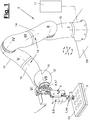
- Figure 1 shows a machining tool (1) with a workpiece (3) acted upon by it, together with a template (50) assigned to the workpiece (3).
- the machining tool (1) has a connector (9) connected feed device (8) for the feed of a machining element (5) for machining the workpiece (3).
- the feed is generated by a movement of the handling device (10) connected to the connection (9).
- the machining tool (1) also has a reinforcement device (4) for the feed, in particular for the feed force, of the machining element (5).
- the reinforcement device (4) is assigned to the feed device (8) and, in particular, is integrated into it.
- the machining tool (1) can also have a support device (7) and, if necessary, a clamping device (46) for supporting and fixing the workpiece.
- the machining tool (1) can have a drive (6) for a proper movement of the advanced machining element (5), for example for a rotary movement.
- the aforementioned components of the machining tool (1) are shown in the drawings of Figure 2 to 7 are shown in detail and are described below.
- the machining tool (1) and the advanced machining element (5) can have a different design for different machining processes.
- the machining tool (1) is designed as a drilling tool and the machining element (5) is designed as a drilling element.
- the aforementioned natural movement of the drilling element (5) is a rotary movement.
- Other suitable tool and process configurations relate to other types of machining techniques, for example grinding, milling, cutting, reaming or the like. Forming techniques, joining techniques or the like can also be implemented. Basically, any machining technique is addressed that requires a feed of a machining element with a Includes feed force.
- the handling device (10) is preferably multi-axis and programmable. It can have any number and combination of rotary and / or translational robot axes and can be combined with an in Figure 1
- the schematically illustrated controller (11), in particular a robot controller, can be connected to control and, if necessary, regulate the robot axes.
- the robot controller (11) can have a computing unit, one or more memories for data or programs, and input and output units. It can save process-relevant data, e.g. sensor data, and log it for quality control and assurance.
- the machining tool (1) with one or more components can also be connected to the control (11) and, for example, as a additional robot axis (s) can be implemented.
- the handling device (10) can be arranged in a stationary manner or by means of a means of transport (53) so that it can be moved around on a substrate.
- the arrows in Figure 1 illustrate, by way of example, the translational and / or rotational movement possibilities that are given as a result.
- the handling device (10) with the connected processing tool (1) can form a working device (3).
- the handling device (10) is shown in FIG Figure 1 designed as a multi-axis and programmable robot.
- the following description of the robot also applies to other types of handling devices (10) with appropriate adaptation.
- Figure 1 shows a special version as a lightweight robot.
- the robot can also have one or more force-controlled or force-regulated robot axes, here, for example, seven axes (I-VII). Furthermore, there may be one or more compliant robot axes with a compliance control.
- the axes (I-VII) each have a pivot bearing and a controllable or regulatable drive assigned here, together with a sensor system (18).
- the robot axes (I-VII) can also have a controllable or switchable brake. Further details are explained below.
- the robot (10) develops only a relatively small feed and feed force acting on the connection (9), which is not sufficient for the feed of the processing element (5) or which brings with it an undesirably high axial load.
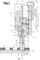
- the reinforcement device (4) provides a remedy here by being set according to Figure 7 a feed movement of the robot (10) with a small force Fr and a long path Vr is translated into a feed movement of the machining element (5) with a larger feed force Fw and a smaller feed path Vw.
- the feed movements are preferably linear and parallel.
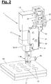
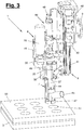
- Figure 2 to 7 show details of the machining tool (1) and its components in external views and in partially broken or sectioned representations.
- the reinforcement device (4) is arranged between the flange-like connection (9) and the processing element (5). It is assigned to the feed device (8) and, in particular, is integrated into it.
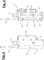
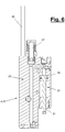
- FIGS 4 to 6 illustrate the details of the amplification device (4). In the other figures only parts of the reinforcement device (4) can be seen.
- the reinforcement device (4) has according to Figure 4 a housing (28), from which a driving actuating element (20) and an aborting actuating element (21) protrude, which are connected to a robot-driven feed element (40) and a tool-driven feed element (35) and also to the connection ( 9) and the processing element (5) are connected.
- the reinforcement device (4) has a transmission (22) between the rod-like actuating elements (20, 21).
- this is a fluidic, in particular hydraulic transmission (22) in the embodiment shown, which has a driving cylinder (23) and a driving cylinder (24) which are connected to one another by lines that allow the fluid to flow over from the driving cylinder (23) ) to the driven cylinder (24).
- the actuating elements (20, 21) are designed as piston rods.
- a vent (27) with an overpressure unit can be arranged on the fluid lines.
- the reinforcement device (4) can also have a return (39), which is only indicated schematically by an arrow and not shown in detail, for example a spring or a controllable return element, for returning after advancement.
- the driving piston (25) has an effective area size which, in accordance with the desired transmission ratio, is smaller than the effective area of the driven piston (26).
- the length of the driving cylinder (23) is correspondingly greater than that of the driving cylinder (24).
- the volumes of the cylinders (23, 24) can be essentially the same.
- the above-described force and path ratios Vr / Vw and Fr / Fw are achieved and set by the translation (22).
- the translation (22) can be different Way be designed, for example as a gear transmission.
- the feed device (8) has a movable feed element (40) which is connected to the connection (9) and which acts on the protruding actuating element (20) via a driver or the like.
- a preferably linear feed bearing (41) is provided for the feed element (40), which is connected to a housing or frame (19) of the machining tool (1), in which the support device (7) described below is connected.
- the feed element (40) is designed, for example, as a slide and the feed bearing as a slide guide.
- a suitable sensor system (43) for distance measurement, a limit switch or the like can be assigned to the feed element (40).
- a controllable fixing device (42), for example in the form of a clamping device, can also be provided for the feed element (40), which, when actuated, blocks the feed device (8) and its mobility, so that a rigid connection between the connection (9) and the machining element ( 5) is produced for the purpose of delivering the machining tool (1) or the like.
- the feed device (8) also has a feed element (35) which is connected to the machining element (5) and which is guided and mounted in the housing (19) by means of a feed guide (36).
- the feed element (35) is designed, for example, as a piston-like feed bridge, which is held and guided in a linearly movable manner in the feed guide (36), for example a cylinder-like bridge guide.
- the feed guide (36) can have a stop (38) to limit the feed, which is formed, for example, on the cylinder base. In the event of a stop, the vent (27) can prevent the fluidic transmission (22) from being overloaded.
- the abortive feed element (35) is connected on the input side to the abortive actuating element (21) of the reinforcement device (4) and has for this purpose, for example, a driver (37) which protrudes through a slot in the wall of the housing (19) and with the Actuating element (21) is connected.
- Figure 2 and 3 show this arrangement.
- the feed element (35) is connected to the machining element (5).
- the processing element (5) consists, for example, according to Figure 7 from a drill (33) which is held in a rotationally locked manner in a coaxially rotating drilling spindle (32).
- the drilling spindle (32) is in turn connected to the driving feed element (35) via an external sleeve which transmits the feed movement to the drilling spindle (32) and the drill (33).
- the machining tool (1) has the aforementioned drive (6), which is present individually or in multiple ways, for a superimposed tool movement.
- the drive (6) is designed as a rotary drive and has a motor (29), for example a pneumatic drive motor and a gear (30) which is connected to a receptacle (34) for the actuating element (5).
- a drive transmission (31) can be interposed, which enables the rotating drive movement and the linear feed movement of the machining element (5) to be superimposed.
- it can be designed, for example, as a splined shaft or as a polygonal shaft.
- the receptacle (34) is designed as a spindle receptacle, which engages over the drilling spindle (32) in the manner of a sleeve and is connected to it via the drive transmission (31) in a rotationally locked and axially movable manner.
- the drill (3) that The drilling spindle (32), the receptacle (34) and the feed element (35) are arranged coaxially and extend in the vertical feed direction.
- the motor (29) is arranged parallel to it.
- the feed elements (35, 40) are movably mounted relative to the support device (7).
- the reinforcement device (4) is connected with its own housing (28), if necessary on the outside of the housing (19) and thereby also connected to the support device (7). In this way, the reinforcement device (4) can receive support in the working position on the workpiece (3) or on the associated template (50).
- the support device (7) has a support means (44). This is e.g. designed as a support tube and concentrically surrounds the processing element (5) and possibly the drive transmission (31). In the embodiment of a drilling spindle (32) shown, the latter can be guided axially on the inside of the support tube (44). A suction nozzle (45) for removing the drilling chips can also be arranged on the support tube (44).
- the support device (7) can interact with a clamping device (46) which enables the support device (7), in particular the support means (44), to be fixed in the working position on the workpiece (3) or on a template (50).
- The, for example, collet-like clamping device (46) has for this purpose a clamping means (47) at the workpiece-side end of the supporting means (44), which is designed, for example, as a clamping sleeve and can have a conical shape.
- the clamping means (47) can be activated and deactivated by means of a controllable actuation (48).
- the actuation (48) is designed, for example, as a lifting unit and is arranged in the housing (19).
- the lifting unit (48) can pull the clamping sleeve (47) axially upwards on the support tube (44) and thereby expand it, whereby the clamping sleeve (47) is clamped in a through opening (51) of the template (50) and thereby also fixes the support means (44) .
- the clamping technique can otherwise be carried out in another suitable manner.
- the template (50) can be fixed and supported via a fastening (52) on the workpiece (3) or at another suitable location.
- the template (50) can have one or more through openings (51), the position of which corresponds to the one or more processing points on the workpiece (3).
- the one or more openings (51) interact with the machining tool (1), in particular with its support device (7) and possibly with its clamping device (46).
- the robot (6) can be arranged in the manner described at the beginning on a transport means (53) which can be moved in multiple axes on a surface.
- This can be a vehicle, an air or sliding cushion unit, a slide arrangement or the like.
- the drive for the transport movement can be generated by the robot (10) itself, whereby it can use its processing tool (1) and the template (50) for setting out and supporting. As a result, he can move along a possibly elongated workpiece (3) and also reach processing points that are outside his normal work area.
- the robot (10) inserts the processing tool (1) in a stretched position into a through opening (51) and fixes itself there via the support and clamping device (7, 46).
- the robot (10) then pulls itself in a contraction movement through its robot axes to this fixing and anchor point, whereby it can detect and track its position via the detected axis positions. Afterward the robot (10) can take up its working position again for the next process or, if necessary, a renewed stretching position and anchor and fix itself in the manner described at the next opening (51). Thanks to the above-described fixing, no separate fixing of the position of the transport means (53) in the process is required for machining the workpiece. However, a corresponding fixing means, for example a stakeout, a brake or the like, can be present.
- Figure 1 shows the aforementioned preferred embodiment of a robot (10), which is designed here as a lightweight robot. It is made of lightweight materials such as light metals and plastic and is also small in size. It has a low weight and a correspondingly limited load capacity, which is up to 20 kg, for example.
- a lightweight robot with a weight of robot (10) and tool (1) of, for example, less than 50 kg, in particular approx. 30 kg, can be mobile and can be transported manually from one place of use to another.
- the robot (10) shown has a plurality of movable members (12, 13, 14, 15) that are connected to one another. These are preferably articulated and connected to one another via the said rotating robot axes (I-VII). Furthermore, individual links (13, 14) can be constructed in several parts and are inherently movable.
- the robot axes (I-VII) and their axle drives, in particular rotary drives and the sensors (18), are connected to the robot controller (11), which can control and regulate the drives or axle drives.
- the output-side end member (12) of the robot (10) is designed, for example, as a robot hand and has an output element (17), for example an output flange, which can be rotated about an axis of rotation (16).
- the axis of rotation (16) forms the last robot axis VII.
- the tool (1) is mounted on the output element (17).
- a possibly hollow one Output element (17) and possibly other robot elements (13,14,15) can be guided by one or more lines for equipment, e.g. power and signal currents, fluids, etc. and come out on the flange (17) and on the tool (1) be connected.
- the aforementioned force control or force regulation of the robot axes (I-VII) relates to the outward action on the output element (17) of the end link (12) and to the reaction forces acting there. Inside the robot, torque control or torque regulation takes place on the rotating axes or axis drives.
- the robot (10) preferably has three or more movable members (12,13,14,15). In the embodiment shown, it has a base member (15) connected to a substrate or the means of transport (53) and the aforementioned end member (12) as well as two intermediate members (13, 14) which are multi-part and rotatable by means of axes III and V .
- the number of intermediate links (13, 14) can alternatively be smaller or larger.
- individual or all of the intermediate links (13, 14) can be designed so as to be non-rotatable and without an additional axis.
- the sensor system (18) can, for example, have one or more sensors on one or more axes (I-VII). These sensors can have the same or different functions. They can in particular be designed as force or torque sensors and designed to detect loads, in particular moments, which act on the robot from the outside via the output element (17). The sensors can also detect rotary movements and possibly rotary positions.
- the aforementioned flexibility control can be implemented by the controller (11) by means of the sensor system (18).
- the robot (10) can hold and guide the tool (1) in a resilient and evasive manner during delivery, whereby e.g. crashes and in particular accidents with people can be avoided.
- the property can also be used for manual teaching and programming with the advantage of quick and easy programming, commissioning and adaptability to different tools (1) and the processes and jobs to be carried out with them. Searching for and finding work positions and also staking points at the openings (51) can also be supported and facilitated via a load detection of the sensor system (18). Angular errors in the relative position of the links (12, 13, 14, 15) can also be detected and corrected if necessary.
- the sensor system (18) can also be used to check the dimensional stability and functionality of the tool (1).
- the robot (10) can, for example, bring the tool (1) with the elements to be checked, in particular the support means (44), into light touch contact at a reference point with a known position, the robot movement and position being monitored and contact by means of the sensors (18) is detected.
- the compliance control avoids damaging collisions and the robot movement is stopped or switched off when a specified load threshold is exceeded.
- TCP programmed tool center point
- the correct functioning of the machining tool (1) and its components can be checked during the advance by monitoring the loads that have occurred.
- the effect of the machining element (5) and the machining process can also be monitored via load detection.
- the robot (6) can be arranged in the manner described at the beginning on a transport means (53) which can be moved in multiple axes on a surface.
- This can be a vehicle, an air cushion unit or the like.
- the drive for the travel movement can be generated by the robot (6) itself, whereby it can use its processing tool (1) and the template (50). As a result, he can move along a possibly elongated tool (3) and also reach processing points that are outside his normal work area.
- the robot (6) inserts the processing tool (1) into a through opening (51) and fixes itself there via the support and clamping device (7, 46). The robot (6) then pulls itself towards this fixing and anchor point by moving its robot axis, whereby it can detect and track its position via the detected axis positions.
- the robot (6) can then assume a stretched position again and anchor and fix itself in the manner described at the next opening (51). Thanks to the above-described fixing, no separate fixing of the position of the transport means (53) in the process is required for machining the workpiece.
- a fixing means for example a stakeout, a brake or the like, can be present.
Landscapes
- Engineering & Computer Science (AREA)
- Mechanical Engineering (AREA)
- Robotics (AREA)
- Manipulator (AREA)
- Multi-Process Working Machines And Systems (AREA)
Claims (15)
- Outil d'usinage, en particulier outil de perçage, comprenant un élément d'usinage (5) agissant sur une pièce (3) et un raccord (9) destiné à un dispositif de manipulation (10), notamment un robot, l'outil d'usinage (1) comportant un dispositif d'avance (8) relié au raccord (9) destiné à l'avance de l'élément d'usinage (5) par déplacement du dispositif de manipulation (10) relié au raccord (9), caractérisé en ce que l'outil d'usinage (1) comporte un dispositif d'amplification (4) destiné à l'avance, en particulier à la force d'avance, de l'élément d'usinage (5), le dispositif d'amplification (4) étant associé au dispositif d'avance (8), de préférence étant intégré à celui-ci, et le dispositif d'amplification (4) comportant une transmission (22) qui comporte un élément d'actionnement menant (20) relié au raccord (9) et un élément d'actionnement mené (21) relié à l'élément d'usinage (5).
- Outil d'usinage selon la revendication 1, caractérisé en ce que l'outil d'usinage (1) comporte un dispositif de support (7) destiné au support côté pièce.
- Outil d'usinage selon la revendication 1 ou 2, caractérisé en ce que l'outil d'usinage (1) comporte un entraînement commandable (6), notamment un entraînement en rotation, destiné au déplacement propre de l'élément d'usinage (5).
- Outil d'usinage selon l'une des revendications précédentes, caractérisé en ce que le dispositif d'amplification (4) est disposé entre le raccord (9) et l'élément d'usinage (5) et comporte une transmission fluidique, notamment hydraulique, ou mécanique (22).
- Outil d'usinage selon l'une des revendications précédentes, caractérisé en ce que le dispositif d'avance (8) comporte un élément d'avance mobile (40) relié au raccord (9), notamment un coulisseau, et un élément d'avance (33) relié à l'élément d'usinage (5), notamment un pont d'avance, les éléments d'avance (33, 40) étant montés de manière mobile par rapport au dispositif de support (7) et étant reliés aux éléments d'actionnement (20, 21) du dispositif d'amplification (4) .
- Outil d'usinage selon la revendication 5, caractérisé en ce que l'élément d'usinage (5) comporte une broche de perçage (32) pourvue d'un foret (33), la broche de perçage (32) étant reliée en rotation d'une part à l'élément d'avance (35), en particulier à un pont d'avance, et d'autre part à un logement de broche rotatif (34) par le biais de la transmission d'entraînement (31), le logement de broche (34) étant relié de son côté à l'entraînement (6).
- Outil d'usinage selon l'une des revendications 2 à 6, caractérisé en ce que le dispositif de support (7) comporte un moyen de support (44) et un dispositif de serrage (46) destiné à fixer ledit moyen à une pièce (3) ou à un gabarit (50) pouvant être relié à la pièce (3), en particulier au niveau d'une ouverture (51).
- Outil d'usinage selon la revendication 7, caractérisé en ce que le moyen de support (44) est réalisé sous la forme d'un tube de support et entoure l'élément d'usinage (5) du côté périphérique et de manière directrice, le tube de support (44) étant relié à un moyen d'aspiration (45).
- Outil d'usinage selon l'une des revendications précédentes, caractérisé en ce que le dispositif d'avance (8) comporte un dispositif de fixation commandable (42).
- Dispositif d'usinage, notamment dispositif de perçage, comprenant un outil d'usinage (1), notamment un outil de perçage, et un dispositif de manipulation (10), notamment un robot, destiné à la manipulation de l'outil d'usinage (1), caractérisé en ce que l'outil d'usinage (1) est conçu selon l'une au moins des revendications 1 à 9.
- Dispositif d'usinage selon la revendication 10, caractérisé en ce que le dispositif d'usinage (2) comporte un gabarit (50) qui peut être relié à une pièce (3) dans une position définie et qui est pourvu d'au moins une ouverture traversante (51) dont la position correspond au niveau de la pièce (3) à un emplacement d'usinage prévu.
- Dispositif d'usinage selon la revendication 10 ou 11, caractérisé en ce que le dispositif de manipulation (10) est réalisé sous la forme d'un robot programmable multiaxes qui comporte un ou plusieurs axes de robot (I - VII) commandés en force ou régulés en force et qui est pourvu d'un système de détection intégré associé (18) qui détecte les contraintes agissantes.
- Dispositif d'usinage selon la revendication 10, 11 ou 12, caractérisé en ce que le robot (10) est transportable et est disposé sur un moyen de transport (53) .
- Procédé d'usinage, notamment de perçage, de pièces (3) à l'aide d'un outil d'usinage (1), notamment d'un outil de perçage, qui est guidé par un dispositif de manipulation (10), notamment un robot (3), et qui comporte un élément d'usinage actif (5) agissant sur une pièce et un raccord (9) destiné au dispositif de manipulation (10), le dispositif de manipulation (1) déplaçant et actionnant un dispositif d'avance (8), relié au raccord (9), de l'outil d'usinage (1) pour faire avancer l'élément d'usinage (5), caractérisé en ce que l'outil d'usinage (1) comporte un dispositif d'amplification (4) destiné à l'avance, en particulier à la force d'avance, de l'élément d'usinage (5), le dispositif d'amplification (4) étant associé au dispositif d'avance (8), de préférence étant intégré à celui-ci, et le dispositif d'amplification (4) comportant une transmission (22) qui comporte un élément d'actionnement menant (20) relié au raccord (9) et un élément d'actionnement mené (21) relié à l'élément d'usinage (5).
- Procédé selon la revendication 14, caractérisé en ce qu'un robot (10) transportable et disposé sur un moyen de transport (53) se déplace par son propre entraînement, ledit robot utilisant l'outil d'usinage (1) comme support et aide au positionnement.
Applications Claiming Priority (1)
| Application Number | Priority Date | Filing Date | Title |
|---|---|---|---|
| DE202011052431U DE202011052431U1 (de) | 2011-12-22 | 2011-12-22 | Bearbeitungswerkzeug |
Publications (3)
| Publication Number | Publication Date |
|---|---|
| EP2623239A2 EP2623239A2 (fr) | 2013-08-07 |
| EP2623239A3 EP2623239A3 (fr) | 2014-11-26 |
| EP2623239B1 true EP2623239B1 (fr) | 2021-10-13 |
Family
ID=47552801
Family Applications (1)
| Application Number | Title | Priority Date | Filing Date |
|---|---|---|---|
| EP12198472.8A Not-in-force EP2623239B1 (fr) | 2011-12-22 | 2012-12-20 | Outil de traitement et procédé de traitement |
Country Status (4)
| Country | Link |
|---|---|
| US (1) | US9061419B2 (fr) |
| EP (1) | EP2623239B1 (fr) |
| CN (1) | CN103170658B (fr) |
| DE (1) | DE202011052431U1 (fr) |
Cited By (1)
| Publication number | Priority date | Publication date | Assignee | Title |
|---|---|---|---|---|
| WO2026027716A1 (fr) * | 2024-08-01 | 2026-02-05 | Airbus Gmbh | Dispositif pour appliquer une force antagoniste et poser un élément de sécurité d'assemblage lors de l'assemblage de deux composants |
Families Citing this family (46)
| Publication number | Priority date | Publication date | Assignee | Title |
|---|---|---|---|---|
| US20100180711A1 (en) | 2009-01-19 | 2010-07-22 | Comau, Inc. | Robotic end effector system and method |
| US9949828B2 (en) | 2012-10-23 | 2018-04-24 | Valtech Cardio, Ltd. | Controlled steering functionality for implant-delivery tool |
| JP5801346B2 (ja) * | 2013-05-27 | 2015-10-28 | 富士重工業株式会社 | 穿孔装置及び穿孔方法 |
| DE102013218823A1 (de) * | 2013-09-19 | 2015-04-02 | Kuka Laboratories Gmbh | Verfahren zum manuell geführten Verstellen der Pose eines Manipulatorarms eines Industrieroboters und zugehöriger Industrieroboter |
| DE202013104389U1 (de) | 2013-09-26 | 2015-01-20 | Daimler Ag | Arbeitsvorrichtung |
| DE202013104392U1 (de) * | 2013-09-26 | 2015-01-12 | Daimler Ag | Arbeitsvorrichtung |
| CN103522067A (zh) * | 2013-10-12 | 2014-01-22 | 芜湖开瑞金属科技有限公司 | 模板全自动钻孔攻丝装置 |
| DE202014100334U1 (de) * | 2014-01-27 | 2015-05-08 | Kuka Systems Gmbh | Roboterwerkzeug |
| JP6311421B2 (ja) * | 2014-04-10 | 2018-04-18 | 株式会社安川電機 | ティーチングシステム、ロボットシステムおよびティーチング方法 |
| CN104162703B (zh) * | 2014-06-27 | 2016-07-06 | 济南大学 | 基于铣孔机械手的塑窗铣孔工艺及装备 |
| JP6423209B2 (ja) * | 2014-09-08 | 2018-11-14 | Dmg森精機株式会社 | 工作機械 |
| US9616503B2 (en) * | 2014-09-10 | 2017-04-11 | The Boeing Company | Apparatuses and methods for processing a confined area of a workpiece |
| CN104308262B (zh) * | 2014-10-11 | 2017-04-19 | 浙江创龙机器人制造有限公司 | 一种圆盘锯片的机械手装置 |
| DE202014105464U1 (de) * | 2014-11-13 | 2016-02-16 | Kuka Systems Gmbh | Halteeinrichtung |
| US10046400B2 (en) | 2014-11-18 | 2018-08-14 | Apex Brands, Inc. | System and method of robotic positioning of multiple tools |
| CN104708050B (zh) * | 2015-02-13 | 2017-03-29 | 深圳市圆梦精密技术研究院 | 柔性钻削系统 |
| CN104646716B (zh) * | 2015-02-13 | 2017-01-25 | 深圳市圆梦精密技术研究院 | 柔性钻削系统 |
| CN104741653B (zh) * | 2015-03-31 | 2017-03-22 | 深圳市圆梦精密技术研究院 | 复合材料零件的孔加工方法 |
| JP6267152B2 (ja) * | 2015-04-14 | 2018-01-24 | ファナック株式会社 | 工具マガジンの工具保持手段の把持力測定手段を備えた工具搬送装置および加工システム |
| US10232897B2 (en) * | 2015-10-16 | 2019-03-19 | The Boeing Company | Walking robot |
| JP6291532B2 (ja) * | 2016-07-13 | 2018-03-14 | 本田技研工業株式会社 | ロボットによる係合確認方法 |
| FR3054158B1 (fr) * | 2016-07-21 | 2019-06-28 | Comau France | Machine-outil d’usinage |
| DE102016216902A1 (de) * | 2016-09-06 | 2018-03-08 | Deckel Maho Pfronten Gmbh | Werkzeugmaschine zur spanenden Bearbeitung eines Werkstücks sowie Spindelträgerbaugruppe zum Einsatz an einer derartigen Werkzeugmaschine |
| CN107102657B (zh) * | 2017-05-25 | 2022-12-23 | 广东省科学院智能制造研究所 | 一种主动柔性力控制设备 |
| CN107378035B (zh) * | 2017-07-31 | 2023-06-27 | 广东利工设备有限公司 | 一种立式数控深孔钻机床 |
| US20190076932A1 (en) * | 2017-09-14 | 2019-03-14 | Spirit Aerosystems, Inc. | Apparatus and method for minimizing elongation in drilled holes |
| WO2019059825A1 (fr) * | 2017-09-21 | 2019-03-28 | Novator Ab | Procédé et système d'usinage d'une pièce à travailler |
| JP6773712B2 (ja) * | 2018-03-27 | 2020-10-21 | ファナック株式会社 | ロボット加工システム |
| CN108672753B (zh) * | 2018-05-17 | 2019-07-02 | 东北大学 | 一种便携式飞机蒙皮钻孔装置 |
| JP2020007095A (ja) * | 2018-07-06 | 2020-01-16 | 株式会社日立ビルシステム | エレベーター据付装置 |
| CN110125455B (zh) * | 2019-05-27 | 2020-06-02 | 清华大学 | 一种用于机器人钻孔中优化钻头位姿的方法 |
| CN110806334B (zh) * | 2019-11-25 | 2022-02-01 | 浙江德稻工程咨询有限公司 | 一种墙体材料多点位取样检测装置 |
| DE102020201528B4 (de) | 2020-02-07 | 2023-11-23 | Deckel Maho Pfronten Gmbh | Werkzeugmaschinenroboter |
| GB2594503A (en) * | 2020-04-30 | 2021-11-03 | Airbus Operations Ltd | Automated clamp |
| CN111482629A (zh) * | 2020-05-22 | 2020-08-04 | 蓝鲸科技(深圳)有限公司 | 一种便携式半自动制孔设备及制孔方法 |
| CN112317792A (zh) * | 2020-09-17 | 2021-02-05 | 国网山东省电力公司昌邑市供电公司 | 一种电气施工用电气打孔装置及使用方法 |
| CN112157284A (zh) * | 2020-09-29 | 2021-01-01 | 蒙美兰 | 一种工业机器人自动化钻孔系统及使用方法 |
| CN112388375B (zh) * | 2020-10-19 | 2024-05-28 | 长沙飞斯特机械制造有限公司 | 一种飞轮料盘夹持工装 |
| CA3203996A1 (fr) * | 2021-02-01 | 2022-08-04 | Abb Schweiz Ag | Ensemble et appareil d'usinage de piece mecanique |
| DE102021201971A1 (de) | 2021-03-02 | 2022-09-08 | Psa Automobiles Sa | Bearbeitungsvorrichtung für eine drehende Bearbeitung |
| US12220751B2 (en) * | 2021-04-16 | 2025-02-11 | The Boeing Company | Robotic drill system and method of drilling with a robotic drill system |
| CN115365998B (zh) * | 2022-08-17 | 2023-06-09 | 安徽瑞林精科股份有限公司 | 一种自动备料系统 |
| CN115818233B (zh) * | 2023-02-21 | 2023-06-13 | 宜宾健翌精密机械制造有限公司 | 一种运输卸料装置 |
| CN116372209B (zh) * | 2023-05-31 | 2023-09-29 | 赣州至越机械有限公司 | 一种差速器外壳钻孔攻丝设备及其使用方法 |
| US20250123168A1 (en) * | 2023-10-11 | 2025-04-17 | The Boeing Company | Systems and methods for identifying mis-aligned holes in structural components |
| CN118204529B (zh) * | 2024-04-28 | 2026-01-16 | 中国长江电力股份有限公司 | 一种水电站联轴销孔类部件的镗孔装置及方法 |
Family Cites Families (16)
| Publication number | Priority date | Publication date | Assignee | Title |
|---|---|---|---|---|
| FR2527967B1 (fr) * | 1982-06-07 | 1985-07-19 | Merlin Gerin | Robot industriel perfectionne pilote par un automate programmable |
| JPS60249519A (ja) * | 1984-05-26 | 1985-12-10 | Daikin Ind Ltd | ロボツト用工具ホルダ− |
| US4611377A (en) * | 1984-06-04 | 1986-09-16 | Eoa Systems, Inc. | Interchangeable robot end-of-arm tooling system |
| US4837983A (en) * | 1986-01-24 | 1989-06-13 | The Boeing Company | Drill bit sharpening apparatus |
| US4995148A (en) * | 1990-03-30 | 1991-02-26 | Imta | Robotically controlled multi-task end effector |
| JP2825623B2 (ja) | 1990-07-23 | 1998-11-18 | 富士重工業株式会社 | 組立ロボット用ドリリングユニット |
| US6382890B1 (en) * | 1999-09-01 | 2002-05-07 | Novator Ab | Hand tool apparatus for orbital drilling |
| DE19962974A1 (de) | 1999-12-24 | 2001-06-28 | Bielomatik Leuze & Co | Vorrichtung und Verfahren zum Heizelementschweissen |
| GB0228259D0 (en) * | 2002-12-04 | 2003-01-08 | Short Brothers Plc | Automated riveting machine |
| WO2008027001A1 (fr) * | 2006-08-31 | 2008-03-06 | Novator Ab | Dispositif de fixation destiné à fixer une foreuse portable sur un gabarit de perçage |
| ITTO20070395A1 (it) * | 2007-06-06 | 2008-12-07 | Bruno Bisiach | Metodo di controllo di una macchina trapanatrice ed apparato che realizza detto metodo. |
| ES2335836B1 (es) * | 2007-06-27 | 2011-02-18 | Airbus Operations, S.L. | Robot portatil. |
| DE102007060680A1 (de) * | 2007-12-17 | 2009-06-18 | Kuka Roboter Gmbh | Verfahren und Einrichtung zur Steuerung eines Manipulators |
| DE102009012154B4 (de) * | 2009-03-06 | 2011-05-05 | Thyssenkrupp Drauz Nothelfer Gmbh | Bearbeitungseinrichtung und Verfahren zur automatisierten Bestimmung eines Gesamtverfahrwegs einer Bearbeitungseinrichtung zur Gewährleistung einer vorbestimmten Überarbeitungstiefe |
| DE102009012155A1 (de) * | 2009-03-06 | 2010-09-09 | Thyssenkrupp Drauz Nothelfer Gmbh | Bearbeitungseinrichtung zur Bearbeitung eines Werkstücks |
| JP5534189B2 (ja) * | 2010-04-02 | 2014-06-25 | 株式会社Ihi | 加工ロボットとその加工制御方法 |
-
2011
- 2011-12-22 DE DE202011052431U patent/DE202011052431U1/de not_active Expired - Lifetime
-
2012
- 2012-12-20 US US13/721,359 patent/US9061419B2/en not_active Expired - Fee Related
- 2012-12-20 EP EP12198472.8A patent/EP2623239B1/fr not_active Not-in-force
- 2012-12-24 CN CN201210566939.5A patent/CN103170658B/zh not_active Expired - Fee Related
Non-Patent Citations (1)
| Title |
|---|
| None * |
Cited By (1)
| Publication number | Priority date | Publication date | Assignee | Title |
|---|---|---|---|---|
| WO2026027716A1 (fr) * | 2024-08-01 | 2026-02-05 | Airbus Gmbh | Dispositif pour appliquer une force antagoniste et poser un élément de sécurité d'assemblage lors de l'assemblage de deux composants |
Also Published As
| Publication number | Publication date |
|---|---|
| CN103170658A (zh) | 2013-06-26 |
| US20130166071A1 (en) | 2013-06-27 |
| CN103170658B (zh) | 2016-08-31 |
| DE202011052431U1 (de) | 2013-03-25 |
| EP2623239A3 (fr) | 2014-11-26 |
| EP2623239A2 (fr) | 2013-08-07 |
| US9061419B2 (en) | 2015-06-23 |
Similar Documents
| Publication | Publication Date | Title |
|---|---|---|
| EP2623239B1 (fr) | Outil de traitement et procédé de traitement | |
| EP2178666B1 (fr) | Dispositif mécanique pour usiner des pièces en forme de barres, comprenant un dispositif d'appui de pièce | |
| EP2729281B1 (fr) | Dispositif de travail et procédé | |
| EP1272409B1 (fr) | Appareil de manipulation servant a transferer des pieces | |
| EP2560861B1 (fr) | Dispositif de transport pour voies d'automatisation | |
| EP1129800B1 (fr) | Dispositif de transport flexible pour presses | |
| EP2666727B1 (fr) | Dispositif de levage pour une machine d'emballage | |
| EP1519797B1 (fr) | Procede pour nettoyer un composant et installation de nettoyage adaptee a cet effet | |
| EP2323795B1 (fr) | Unité de percussion avec manivelle excentrique | |
| DE10301237A1 (de) | Robotervorrichtung mit einer Roboterhand für Hochlastarbeit | |
| DE2916312A1 (de) | Greifzange fuer handhabungsgeraete | |
| EP0213256B1 (fr) | Dispositif de brunissage | |
| WO2007073901A2 (fr) | Machine a cintrer | |
| EP1170218A1 (fr) | Dispositif de préhension pour pièces minces en forme de plaque | |
| DE68904694T2 (de) | Spannmechanismus eines geraetes zum bohren oder senken von loechern in einem werkstueck. | |
| DE202013105910U1 (de) | Roboterwerkzeug | |
| EP0320498A2 (fr) | Robot industriel | |
| DE102018121968A1 (de) | Werkzeugmaschine zum Bearbeiten von Werkstücken | |
| EP3079861A1 (fr) | Dispositif et procédé de travail | |
| AT524630B1 (de) | Biegeanlage und Manipulator mit rotierbarer Greiferanordnung | |
| WO2015110623A1 (fr) | Outil de robot, procédé de fonctionnement et dispositif de travail | |
| EP3112083B1 (fr) | Système de portique d'une machine-outil et machine-outil avec un tel système de portique | |
| DE10135233A1 (de) | Ringmaschine | |
| EP2566635B1 (fr) | Porte-outil, machine-outil comprenant un tel porte-outil, et procédé pour fixer un outil d'usinage sur un porte-outil d'une machine-outil | |
| WO2015135917A2 (fr) | Procédé pour faire fonctionner un robot et robot correspondant équipé d'un dispositif palpeur mécanique |
Legal Events
| Date | Code | Title | Description |
|---|---|---|---|
| PUAI | Public reference made under article 153(3) epc to a published international application that has entered the european phase |
Free format text: ORIGINAL CODE: 0009012 |
|
| AK | Designated contracting states |
Kind code of ref document: A2 Designated state(s): AL AT BE BG CH CY CZ DE DK EE ES FI FR GB GR HR HU IE IS IT LI LT LU LV MC MK MT NL NO PL PT RO RS SE SI SK SM TR |
|
| AX | Request for extension of the european patent |
Extension state: BA ME |
|
| PUAL | Search report despatched |
Free format text: ORIGINAL CODE: 0009013 |
|
| AK | Designated contracting states |
Kind code of ref document: A3 Designated state(s): AL AT BE BG CH CY CZ DE DK EE ES FI FR GB GR HR HU IE IS IT LI LT LU LV MC MK MT NL NO PL PT RO RS SE SI SK SM TR |
|
| AX | Request for extension of the european patent |
Extension state: BA ME |
|
| RIC1 | Information provided on ipc code assigned before grant |
Ipc: B23B 39/24 20060101ALI20141022BHEP Ipc: B25J 9/16 20060101ALI20141022BHEP Ipc: B23Q 3/06 20060101ALI20141022BHEP Ipc: B23Q 5/22 20060101ALI20141022BHEP Ipc: B23Q 5/26 20060101ALI20141022BHEP Ipc: B25J 11/00 20060101ALI20141022BHEP Ipc: F15B 3/00 20060101ALI20141022BHEP Ipc: B23B 39/00 20060101ALI20141022BHEP Ipc: B23B 35/00 20060101AFI20141022BHEP Ipc: B25J 15/00 20060101ALI20141022BHEP |
|
| 17P | Request for examination filed |
Effective date: 20150526 |
|
| RBV | Designated contracting states (corrected) |
Designated state(s): AL AT BE BG CH CY CZ DE DK EE ES FI FR GB GR HR HU IE IS IT LI LT LU LV MC MK MT NL NO PL PT RO RS SE SI SK SM TR |
|
| STAA | Information on the status of an ep patent application or granted ep patent |
Free format text: STATUS: EXAMINATION IS IN PROGRESS |
|
| 17Q | First examination report despatched |
Effective date: 20180622 |
|
| GRAP | Despatch of communication of intention to grant a patent |
Free format text: ORIGINAL CODE: EPIDOSNIGR1 |
|
| STAA | Information on the status of an ep patent application or granted ep patent |
Free format text: STATUS: GRANT OF PATENT IS INTENDED |
|
| INTG | Intention to grant announced |
Effective date: 20210511 |
|
| GRAS | Grant fee paid |
Free format text: ORIGINAL CODE: EPIDOSNIGR3 |
|
| GRAA | (expected) grant |
Free format text: ORIGINAL CODE: 0009210 |
|
| STAA | Information on the status of an ep patent application or granted ep patent |
Free format text: STATUS: THE PATENT HAS BEEN GRANTED |
|
| AK | Designated contracting states |
Kind code of ref document: B1 Designated state(s): AL AT BE BG CH CY CZ DE DK EE ES FI FR GB GR HR HU IE IS IT LI LT LU LV MC MK MT NL NO PL PT RO RS SE SI SK SM TR |
|
| REG | Reference to a national code |
Ref country code: GB Ref legal event code: FG4D Free format text: NOT ENGLISH |
|
| REG | Reference to a national code |
Ref country code: CH Ref legal event code: EP |
|
| REG | Reference to a national code |
Ref country code: DE Ref legal event code: R096 Ref document number: 502012016926 Country of ref document: DE |
|
| REG | Reference to a national code |
Ref country code: IE Ref legal event code: FG4D Free format text: LANGUAGE OF EP DOCUMENT: GERMAN |
|
| REG | Reference to a national code |
Ref country code: AT Ref legal event code: REF Ref document number: 1437813 Country of ref document: AT Kind code of ref document: T Effective date: 20211115 |
|
| REG | Reference to a national code |
Ref country code: LT Ref legal event code: MG9D |
|
| REG | Reference to a national code |
Ref country code: NL Ref legal event code: MP Effective date: 20211013 |
|
| PG25 | Lapsed in a contracting state [announced via postgrant information from national office to epo] |
Ref country code: RS Free format text: LAPSE BECAUSE OF FAILURE TO SUBMIT A TRANSLATION OF THE DESCRIPTION OR TO PAY THE FEE WITHIN THE PRESCRIBED TIME-LIMIT Effective date: 20211013 Ref country code: LT Free format text: LAPSE BECAUSE OF FAILURE TO SUBMIT A TRANSLATION OF THE DESCRIPTION OR TO PAY THE FEE WITHIN THE PRESCRIBED TIME-LIMIT Effective date: 20211013 Ref country code: FI Free format text: LAPSE BECAUSE OF FAILURE TO SUBMIT A TRANSLATION OF THE DESCRIPTION OR TO PAY THE FEE WITHIN THE PRESCRIBED TIME-LIMIT Effective date: 20211013 Ref country code: BG Free format text: LAPSE BECAUSE OF FAILURE TO SUBMIT A TRANSLATION OF THE DESCRIPTION OR TO PAY THE FEE WITHIN THE PRESCRIBED TIME-LIMIT Effective date: 20220113 |
|
| PG25 | Lapsed in a contracting state [announced via postgrant information from national office to epo] |
Ref country code: IS Free format text: LAPSE BECAUSE OF FAILURE TO SUBMIT A TRANSLATION OF THE DESCRIPTION OR TO PAY THE FEE WITHIN THE PRESCRIBED TIME-LIMIT Effective date: 20220213 Ref country code: SE Free format text: LAPSE BECAUSE OF FAILURE TO SUBMIT A TRANSLATION OF THE DESCRIPTION OR TO PAY THE FEE WITHIN THE PRESCRIBED TIME-LIMIT Effective date: 20211013 Ref country code: PT Free format text: LAPSE BECAUSE OF FAILURE TO SUBMIT A TRANSLATION OF THE DESCRIPTION OR TO PAY THE FEE WITHIN THE PRESCRIBED TIME-LIMIT Effective date: 20220214 Ref country code: PL Free format text: LAPSE BECAUSE OF FAILURE TO SUBMIT A TRANSLATION OF THE DESCRIPTION OR TO PAY THE FEE WITHIN THE PRESCRIBED TIME-LIMIT Effective date: 20211013 Ref country code: NO Free format text: LAPSE BECAUSE OF FAILURE TO SUBMIT A TRANSLATION OF THE DESCRIPTION OR TO PAY THE FEE WITHIN THE PRESCRIBED TIME-LIMIT Effective date: 20220113 Ref country code: NL Free format text: LAPSE BECAUSE OF FAILURE TO SUBMIT A TRANSLATION OF THE DESCRIPTION OR TO PAY THE FEE WITHIN THE PRESCRIBED TIME-LIMIT Effective date: 20211013 Ref country code: LV Free format text: LAPSE BECAUSE OF FAILURE TO SUBMIT A TRANSLATION OF THE DESCRIPTION OR TO PAY THE FEE WITHIN THE PRESCRIBED TIME-LIMIT Effective date: 20211013 Ref country code: HR Free format text: LAPSE BECAUSE OF FAILURE TO SUBMIT A TRANSLATION OF THE DESCRIPTION OR TO PAY THE FEE WITHIN THE PRESCRIBED TIME-LIMIT Effective date: 20211013 Ref country code: GR Free format text: LAPSE BECAUSE OF FAILURE TO SUBMIT A TRANSLATION OF THE DESCRIPTION OR TO PAY THE FEE WITHIN THE PRESCRIBED TIME-LIMIT Effective date: 20220114 Ref country code: ES Free format text: LAPSE BECAUSE OF FAILURE TO SUBMIT A TRANSLATION OF THE DESCRIPTION OR TO PAY THE FEE WITHIN THE PRESCRIBED TIME-LIMIT Effective date: 20211013 |
|
| REG | Reference to a national code |
Ref country code: DE Ref legal event code: R119 Ref document number: 502012016926 Country of ref document: DE |
|
| PG25 | Lapsed in a contracting state [announced via postgrant information from national office to epo] |
Ref country code: SM Free format text: LAPSE BECAUSE OF FAILURE TO SUBMIT A TRANSLATION OF THE DESCRIPTION OR TO PAY THE FEE WITHIN THE PRESCRIBED TIME-LIMIT Effective date: 20211013 Ref country code: SK Free format text: LAPSE BECAUSE OF FAILURE TO SUBMIT A TRANSLATION OF THE DESCRIPTION OR TO PAY THE FEE WITHIN THE PRESCRIBED TIME-LIMIT Effective date: 20211013 Ref country code: RO Free format text: LAPSE BECAUSE OF FAILURE TO SUBMIT A TRANSLATION OF THE DESCRIPTION OR TO PAY THE FEE WITHIN THE PRESCRIBED TIME-LIMIT Effective date: 20211013 Ref country code: MC Free format text: LAPSE BECAUSE OF FAILURE TO SUBMIT A TRANSLATION OF THE DESCRIPTION OR TO PAY THE FEE WITHIN THE PRESCRIBED TIME-LIMIT Effective date: 20211013 Ref country code: EE Free format text: LAPSE BECAUSE OF FAILURE TO SUBMIT A TRANSLATION OF THE DESCRIPTION OR TO PAY THE FEE WITHIN THE PRESCRIBED TIME-LIMIT Effective date: 20211013 Ref country code: DK Free format text: LAPSE BECAUSE OF FAILURE TO SUBMIT A TRANSLATION OF THE DESCRIPTION OR TO PAY THE FEE WITHIN THE PRESCRIBED TIME-LIMIT Effective date: 20211013 Ref country code: CZ Free format text: LAPSE BECAUSE OF FAILURE TO SUBMIT A TRANSLATION OF THE DESCRIPTION OR TO PAY THE FEE WITHIN THE PRESCRIBED TIME-LIMIT Effective date: 20211013 |
|
| REG | Reference to a national code |
Ref country code: CH Ref legal event code: PL |
|
| PLBE | No opposition filed within time limit |
Free format text: ORIGINAL CODE: 0009261 |
|
| STAA | Information on the status of an ep patent application or granted ep patent |
Free format text: STATUS: NO OPPOSITION FILED WITHIN TIME LIMIT |
|
| 26N | No opposition filed |
Effective date: 20220714 |
|
| REG | Reference to a national code |
Ref country code: BE Ref legal event code: MM Effective date: 20211231 |
|
| GBPC | Gb: european patent ceased through non-payment of renewal fee |
Effective date: 20220113 |
|
| PG25 | Lapsed in a contracting state [announced via postgrant information from national office to epo] |
Ref country code: LU Free format text: LAPSE BECAUSE OF NON-PAYMENT OF DUE FEES Effective date: 20211220 Ref country code: IE Free format text: LAPSE BECAUSE OF NON-PAYMENT OF DUE FEES Effective date: 20211220 Ref country code: GB Free format text: LAPSE BECAUSE OF NON-PAYMENT OF DUE FEES Effective date: 20220113 Ref country code: DE Free format text: LAPSE BECAUSE OF NON-PAYMENT OF DUE FEES Effective date: 20220701 Ref country code: AL Free format text: LAPSE BECAUSE OF FAILURE TO SUBMIT A TRANSLATION OF THE DESCRIPTION OR TO PAY THE FEE WITHIN THE PRESCRIBED TIME-LIMIT Effective date: 20211013 |
|
| PG25 | Lapsed in a contracting state [announced via postgrant information from national office to epo] |
Ref country code: SI Free format text: LAPSE BECAUSE OF FAILURE TO SUBMIT A TRANSLATION OF THE DESCRIPTION OR TO PAY THE FEE WITHIN THE PRESCRIBED TIME-LIMIT Effective date: 20211013 Ref country code: FR Free format text: LAPSE BECAUSE OF NON-PAYMENT OF DUE FEES Effective date: 20211231 Ref country code: BE Free format text: LAPSE BECAUSE OF NON-PAYMENT OF DUE FEES Effective date: 20211231 |
|
| PG25 | Lapsed in a contracting state [announced via postgrant information from national office to epo] |
Ref country code: LI Free format text: LAPSE BECAUSE OF NON-PAYMENT OF DUE FEES Effective date: 20211231 Ref country code: CH Free format text: LAPSE BECAUSE OF NON-PAYMENT OF DUE FEES Effective date: 20211231 |
|
| REG | Reference to a national code |
Ref country code: AT Ref legal event code: MM01 Ref document number: 1437813 Country of ref document: AT Kind code of ref document: T Effective date: 20211220 |
|
| PG25 | Lapsed in a contracting state [announced via postgrant information from national office to epo] |
Ref country code: AT Free format text: LAPSE BECAUSE OF NON-PAYMENT OF DUE FEES Effective date: 20211220 |
|
| PG25 | Lapsed in a contracting state [announced via postgrant information from national office to epo] |
Ref country code: IT Free format text: LAPSE BECAUSE OF FAILURE TO SUBMIT A TRANSLATION OF THE DESCRIPTION OR TO PAY THE FEE WITHIN THE PRESCRIBED TIME-LIMIT Effective date: 20211013 Ref country code: HU Free format text: LAPSE BECAUSE OF FAILURE TO SUBMIT A TRANSLATION OF THE DESCRIPTION OR TO PAY THE FEE WITHIN THE PRESCRIBED TIME-LIMIT; INVALID AB INITIO Effective date: 20121220 Ref country code: CY Free format text: LAPSE BECAUSE OF FAILURE TO SUBMIT A TRANSLATION OF THE DESCRIPTION OR TO PAY THE FEE WITHIN THE PRESCRIBED TIME-LIMIT Effective date: 20211013 |
|
| P01 | Opt-out of the competence of the unified patent court (upc) registered |
Effective date: 20230528 |
|
| PG25 | Lapsed in a contracting state [announced via postgrant information from national office to epo] |
Ref country code: MK Free format text: LAPSE BECAUSE OF FAILURE TO SUBMIT A TRANSLATION OF THE DESCRIPTION OR TO PAY THE FEE WITHIN THE PRESCRIBED TIME-LIMIT Effective date: 20211013 |
|
| PG25 | Lapsed in a contracting state [announced via postgrant information from national office to epo] |
Ref country code: TR Free format text: LAPSE BECAUSE OF FAILURE TO SUBMIT A TRANSLATION OF THE DESCRIPTION OR TO PAY THE FEE WITHIN THE PRESCRIBED TIME-LIMIT Effective date: 20211013 |
|
| PG25 | Lapsed in a contracting state [announced via postgrant information from national office to epo] |
Ref country code: MT Free format text: LAPSE BECAUSE OF FAILURE TO SUBMIT A TRANSLATION OF THE DESCRIPTION OR TO PAY THE FEE WITHIN THE PRESCRIBED TIME-LIMIT Effective date: 20211013 |