EP2630307B1 - Fondation pour une éolienne et procédé de fabrication de celle-ci - Google Patents
Fondation pour une éolienne et procédé de fabrication de celle-ci Download PDFInfo
- Publication number
- EP2630307B1 EP2630307B1 EP11776076.9A EP11776076A EP2630307B1 EP 2630307 B1 EP2630307 B1 EP 2630307B1 EP 11776076 A EP11776076 A EP 11776076A EP 2630307 B1 EP2630307 B1 EP 2630307B1
- Authority
- EP
- European Patent Office
- Prior art keywords
- foundation
- base
- sections
- tensioning
- tensioning elements
- Prior art date
- Legal status (The legal status is an assumption and is not a legal conclusion. Google has not performed a legal analysis and makes no representation as to the accuracy of the status listed.)
- Not-in-force
Links
- 238000004519 manufacturing process Methods 0.000 title 1
- XLYOFNOQVPJJNP-UHFFFAOYSA-N water Substances O XLYOFNOQVPJJNP-UHFFFAOYSA-N 0.000 claims description 53
- 238000000034 method Methods 0.000 claims description 42
- 238000009434 installation Methods 0.000 claims description 21
- 239000000463 material Substances 0.000 claims description 17
- 239000000945 filler Substances 0.000 claims description 11
- 238000013461 design Methods 0.000 claims description 6
- 230000008878 coupling Effects 0.000 claims 1
- 238000010168 coupling process Methods 0.000 claims 1
- 238000005859 coupling reaction Methods 0.000 claims 1
- 239000004567 concrete Substances 0.000 description 9
- 238000010276 construction Methods 0.000 description 4
- 238000002360 preparation method Methods 0.000 description 4
- 230000005484 gravity Effects 0.000 description 3
- 230000000694 effects Effects 0.000 description 2
- 230000007774 longterm Effects 0.000 description 2
- 239000011150 reinforced concrete Substances 0.000 description 2
- 229910000831 Steel Inorganic materials 0.000 description 1
- 238000013459 approach Methods 0.000 description 1
- 239000011324 bead Substances 0.000 description 1
- 238000005266 casting Methods 0.000 description 1
- 230000007812 deficiency Effects 0.000 description 1
- 230000007613 environmental effect Effects 0.000 description 1
- 238000003780 insertion Methods 0.000 description 1
- 230000037431 insertion Effects 0.000 description 1
- 238000012986 modification Methods 0.000 description 1
- 230000004048 modification Effects 0.000 description 1
- 229920002635 polyurethane Polymers 0.000 description 1
- 239000004814 polyurethane Substances 0.000 description 1
- 230000001681 protective effect Effects 0.000 description 1
- 230000000284 resting effect Effects 0.000 description 1
- 150000003839 salts Chemical class 0.000 description 1
- 238000007789 sealing Methods 0.000 description 1
- 239000007787 solid Substances 0.000 description 1
- 239000010959 steel Substances 0.000 description 1
Images




Classifications
-
- F—MECHANICAL ENGINEERING; LIGHTING; HEATING; WEAPONS; BLASTING
- F03—MACHINES OR ENGINES FOR LIQUIDS; WIND, SPRING, OR WEIGHT MOTORS; PRODUCING MECHANICAL POWER OR A REACTIVE PROPULSIVE THRUST, NOT OTHERWISE PROVIDED FOR
- F03D—WIND MOTORS
- F03D13/00—Assembly, mounting or commissioning of wind motors; Arrangements specially adapted for transporting wind motor components
- F03D13/20—Arrangements for mounting or supporting wind motors; Masts or towers for wind motors
- F03D13/22—Foundations specially adapted for wind motors
-
- E—FIXED CONSTRUCTIONS
- E02—HYDRAULIC ENGINEERING; FOUNDATIONS; SOIL SHIFTING
- E02D—FOUNDATIONS; EXCAVATIONS; EMBANKMENTS; UNDERGROUND OR UNDERWATER STRUCTURES
- E02D27/00—Foundations as substructures
- E02D27/32—Foundations for special purposes
- E02D27/42—Foundations for poles, masts or chimneys
-
- E—FIXED CONSTRUCTIONS
- E02—HYDRAULIC ENGINEERING; FOUNDATIONS; SOIL SHIFTING
- E02D—FOUNDATIONS; EXCAVATIONS; EMBANKMENTS; UNDERGROUND OR UNDERWATER STRUCTURES
- E02D27/00—Foundations as substructures
- E02D27/32—Foundations for special purposes
- E02D27/42—Foundations for poles, masts or chimneys
- E02D27/425—Foundations for poles, masts or chimneys specially adapted for wind motors masts
-
- E—FIXED CONSTRUCTIONS
- E04—BUILDING
- E04H—BUILDINGS OR LIKE STRUCTURES FOR PARTICULAR PURPOSES; SWIMMING OR SPLASH BATHS OR POOLS; MASTS; FENCING; TENTS OR CANOPIES, IN GENERAL
- E04H12/00—Towers; Masts or poles; Chimney stacks; Water-towers; Methods of erecting such structures
- E04H12/34—Arrangements for erecting or lowering towers, masts, poles, chimney stacks, or the like
- E04H12/342—Arrangements for stacking tower sections on top of each other
-
- F—MECHANICAL ENGINEERING; LIGHTING; HEATING; WEAPONS; BLASTING
- F05—INDEXING SCHEMES RELATING TO ENGINES OR PUMPS IN VARIOUS SUBCLASSES OF CLASSES F01-F04
- F05B—INDEXING SCHEME RELATING TO WIND, SPRING, WEIGHT, INERTIA OR LIKE MOTORS, TO MACHINES OR ENGINES FOR LIQUIDS COVERED BY SUBCLASSES F03B, F03D AND F03G
- F05B2230/00—Manufacture
- F05B2230/60—Assembly methods
-
- F—MECHANICAL ENGINEERING; LIGHTING; HEATING; WEAPONS; BLASTING
- F05—INDEXING SCHEMES RELATING TO ENGINES OR PUMPS IN VARIOUS SUBCLASSES OF CLASSES F01-F04
- F05B—INDEXING SCHEME RELATING TO WIND, SPRING, WEIGHT, INERTIA OR LIKE MOTORS, TO MACHINES OR ENGINES FOR LIQUIDS COVERED BY SUBCLASSES F03B, F03D AND F03G
- F05B2240/00—Components
- F05B2240/40—Use of a multiplicity of similar components
-
- Y—GENERAL TAGGING OF NEW TECHNOLOGICAL DEVELOPMENTS; GENERAL TAGGING OF CROSS-SECTIONAL TECHNOLOGIES SPANNING OVER SEVERAL SECTIONS OF THE IPC; TECHNICAL SUBJECTS COVERED BY FORMER USPC CROSS-REFERENCE ART COLLECTIONS [XRACs] AND DIGESTS
- Y02—TECHNOLOGIES OR APPLICATIONS FOR MITIGATION OR ADAPTATION AGAINST CLIMATE CHANGE
- Y02E—REDUCTION OF GREENHOUSE GAS [GHG] EMISSIONS, RELATED TO ENERGY GENERATION, TRANSMISSION OR DISTRIBUTION
- Y02E10/00—Energy generation through renewable energy sources
- Y02E10/70—Wind energy
- Y02E10/72—Wind turbines with rotation axis in wind direction
-
- Y—GENERAL TAGGING OF NEW TECHNOLOGICAL DEVELOPMENTS; GENERAL TAGGING OF CROSS-SECTIONAL TECHNOLOGIES SPANNING OVER SEVERAL SECTIONS OF THE IPC; TECHNICAL SUBJECTS COVERED BY FORMER USPC CROSS-REFERENCE ART COLLECTIONS [XRACs] AND DIGESTS
- Y02—TECHNOLOGIES OR APPLICATIONS FOR MITIGATION OR ADAPTATION AGAINST CLIMATE CHANGE
- Y02E—REDUCTION OF GREENHOUSE GAS [GHG] EMISSIONS, RELATED TO ENERGY GENERATION, TRANSMISSION OR DISTRIBUTION
- Y02E10/00—Energy generation through renewable energy sources
- Y02E10/70—Wind energy
- Y02E10/728—Onshore wind turbines
-
- Y—GENERAL TAGGING OF NEW TECHNOLOGICAL DEVELOPMENTS; GENERAL TAGGING OF CROSS-SECTIONAL TECHNOLOGIES SPANNING OVER SEVERAL SECTIONS OF THE IPC; TECHNICAL SUBJECTS COVERED BY FORMER USPC CROSS-REFERENCE ART COLLECTIONS [XRACs] AND DIGESTS
- Y02—TECHNOLOGIES OR APPLICATIONS FOR MITIGATION OR ADAPTATION AGAINST CLIMATE CHANGE
- Y02P—CLIMATE CHANGE MITIGATION TECHNOLOGIES IN THE PRODUCTION OR PROCESSING OF GOODS
- Y02P70/00—Climate change mitigation technologies in the production process for final industrial or consumer products
- Y02P70/50—Manufacturing or production processes characterised by the final manufactured product
-
- Y—GENERAL TAGGING OF NEW TECHNOLOGICAL DEVELOPMENTS; GENERAL TAGGING OF CROSS-SECTIONAL TECHNOLOGIES SPANNING OVER SEVERAL SECTIONS OF THE IPC; TECHNICAL SUBJECTS COVERED BY FORMER USPC CROSS-REFERENCE ART COLLECTIONS [XRACs] AND DIGESTS
- Y10—TECHNICAL SUBJECTS COVERED BY FORMER USPC
- Y10T—TECHNICAL SUBJECTS COVERED BY FORMER US CLASSIFICATION
- Y10T29/00—Metal working
- Y10T29/49—Method of mechanical manufacture
- Y10T29/49316—Impeller making
Definitions
- This application relates generally to foundations for wind turbines and, more particularly, to a modular foundation and a method for making such a modular foundation for an offshore wind turbine installation.
- Wind turbines for converting wind energy to electrical power have been known and applied for many years, but have found a dramatically increased application as an alternative energy source during the last couple of decades. It has become common to place wind turbines together in large groups, often counting in the hundreds, within a restricted area. Such large collections of wind turbines can provide an environmentally less desirable solution both from an aesthetic point of view and also due to the inevitable noise issues they may raise. Furthermore, the positioning of wind turbines on land may not always be an optimal placement, as it is preferable that the blades of the wind turbine be located in a laminar flow of air, which is not always obtained on land due to, for instance, the presence of hills, woods, buildings, etc.
- a wind turbine tower is generally 50-100 m in height with weights approaching 100 tons or more for a turbine with a 90 m rotor diameter (e.g., 2 MW unit). Due to the large dimensions of present day wind turbines, dimensions which furthermore tend to increase due to the relation between the diameter of the rotor and the maximum electrical power which the wind turbine can provide; the forces formed by rotational movement of the wind turbine blades; and the very large surface of the tower being exposed to the wind, it is vitally important that the wind turbine be provided with a stable foundation. This is not in principle a problem for wind turbines located onshore, but becomes more problematic in connection with offshore wind turbine installations.
- one solution is to mount the tower of the wind turbine on a suitable construction of pillows and grids, which are in turn fixed to a firm foundation on the bottom of the sea.
- the options become more limited.
- various floating foundations have been utilized to support the wind turbine.
- WO 01/73292 discloses a floating offshore wind power installation.
- Such floating foundations may be relatively complex in their design, expensive to construct and assemble, and difficult to install in the sea.
- an offshore tower structure is formed of stacked pre-fabricated sections extending from a foundation on the seabed to above the water surface.
- Alternative designs may include pile foundations or gravity-based foundations.
- the foundation is typically formed as a one-piece structure, such as quayside, and then subsequently transported to the offshore installation site and positioned within the sea. While this may be acceptable for shallow water depths, for medium water depths, the foundations are extremely large in size (e.g., over 100 m in length) and the transport and installation of such large structures is complex and costly.
- heavy lift crane vessels are typically used to unload the foundation and locate it on the seabed. Additionally, it may be difficult to control and guide the large, one-piece foundation as it is being lowered toward the seabed.
- these foundations may utilize ballasts or other devices to help sink and stabilize the foundation and may also require costly preparation of the seabed prior to installation.
- a method of assembling a foundation for an offshore wind turbine installation involves: lowering the base of the foundation through a body of water so as to position the base on a seabed; arranging a plurality of tensioning elements for post-tensioning of the foundation so as to extend from the base to a second location positioned adjacent a surface of the body of water; threading an end of the tensioning elements at the second location through bores formed in a foundation section and lowering towards the base so that movement of the foundation section toward the base is guided by the tensioning elements; and repeating the threading and lowering steps to stack a plurality of foundation sections on the base and thereby assemble the wind turbine foundation.
- the second location is preferably above the surface of the body of water, so as to be accessible by a vessel, for example.
- the foundation sections may be threaded onto the tensioning elements topside and then lowered into the water.
- the tensioning of the tensioning elements may be done after having stacked the foundation segments, and also done above the surface of the body of water, for example from a vessel.
- a method of assembling a modular foundation for a wind turbine having a base and a plurality of foundation sections includes positioning the base of the foundation on a support surface; arranging a plurality of tensioning elements for post-tensioning of the foundation so as to extend from the base to a second location spaced from the base; and stacking a plurality of foundation sections on the base by guiding the foundation sections from the second location toward the base using the tensioning elements.
- Each of the foundation sections includes a plurality of bores formed through the sections and the foundation sections are threaded sequentially onto an end of the tensioning elements at the second location so that movement of the sections toward the base is guided by the tensioning elements.
- the tensioning elements may be used to, in essence, provide a self-alignment feature for the bores extending through the plurality of foundation sections. Subsequent to stacking the foundation elements and with the bores aligned, the bores may be filled with a filler material to protect the tensioning elements from, for example, a water environment.
- each of the foundation sections may also include a central passageway inboard of the bores and these passageways may become self-aligned as a result of guiding the foundation sections with the tensioning elements. Subsequent to stacking the foundation elements and with the central passageways aligned, the passageways may be filled with a filler material to increase the weight, as thus stability, of the overall foundation.
- the tensioning elements may be tensioned to increase the strength and structural integrity of the foundation. In one aspect of the invention, such post-tensioning may be accomplished at the top end of the foundation.
- the second location may be above the surface of the water so as to be accessible by a vessel, for example.
- the foundation sections may be threaded onto the tensioning elements topside and then lowered into the water. Additionally, the tensioning of the tensioning elements may also be done topside. With such a foundation assembled, a wind turbine may be erected on the foundation.
- a foundation for an offshore wind turbine installation includes a base positioned on the seabed of a body of water; a plurality of tensioning elements; and a plurality of serially stacked foundation segments on top of the base.
- Each tensioning element includes a first end permanently embedded within the base and a second end that is adjacent the surface of the body of water, the tensioning elements being tensioned to compress the foundation.
- each foundation section has a plurality of bores each of which is configured to receive a respective one of the plurality of tensioning elements therethrough.
- the stacked foundation sections extend to a location above the surface of the body of water.
- an offshore wind turbine installation 10 includes a foundation 12 generally disposed in a body of water 14 and supported by the seabed 16, and a wind turbine 18 fixedly secured to the foundation 12.
- the wind turbine 18 includes a tower 20, a nacelle 22 disposed at the apex of the tower 20, and a rotor 24 operatively coupled to a generator (not shown) housed inside the nacelle 14.
- the rotor 24 includes a central hub 26 and a plurality of blades 28 that project outwardly from the central hub 20 at locations circumferentially distributed thereabout.
- the blades 28 are configured to interact with the passing air flow to produce lift that causes the central hub 26 to spin about its central axis.
- the foundation 12 is designed so as to provide a lower cost, less complex alternative to existing methods and foundations used in medium water depth wind turbine installations. More particularly, foundation 12 has a modular design that overcomes many of the drawbacks of existing foundations and their installation.
- foundation 12 includes a base 30 configured to be supported on the seabed 16, and a plurality of serially stacked foundation sections 32 arranged on top of the base 30 and configured to extend to adjacent the surface 34 of the water 14.
- the foundation sections 32 may extend slightly above the surface 34 of the water 14, as illustrated in Fig. 1 .
- the foundation 12 may further include a platform 36 to which the wind turbine 18 is secured.
- foundation 12 is configured as a gravity foundation wherein the collective weight of the foundation 12 sufficiently stabilizes the wind turbine 18 relative to the seabed 16. In this way, the costs associated with piles, ballasts, extensive seabed preparation, etc. may be avoided or at least reduced. However, unlike other gravity foundations, these cost benefits may be achieved while also minimizing transportation and assembly costs, as will now be explained.
- the base 30 is configured to rest on the seabed 16 and, in one embodiment, may be formed as a generally solid body having a generally cylindrical configuration.
- the base 30 is shown and described as being generally cylindrical, it should be recognized that the base 30 may have a wide range of shapes including rectangular, square, triangular, octagonal, etc (not shown).
- the base 30 may be formed from concrete, reinforced concrete, or other materials suitable for long term submersion in a water environment including, for example, a salt water environment.
- the cross dimension and the height of the base 30 may vary depending on the particular wind turbine installation (e.g., water depth, general water conditions, wind turbine size, etc.).
- the base 30 may be generally larger and heavier than the foundation sections 32 that make up a significant portion of the foundation construction. As is recognized, configuring the base 30 larger than the foundation sections 32 provides for a more stable modular configuration.
- foundation 12 includes tensioning elements that enhance the strength and structural integrity of the overall foundation 12.
- the foundation 12 includes a plurality of tensioning cables 38 extending along at least a portion of the length of the foundation 12.
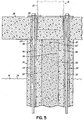
- the tensioning cables 38 may extend from the base 30 to adjacent the surface 34 of the water 14, such as at platform 36 ( Fig. 5 ).
- base 30 includes a plurality of tensioning cables 38 having a first end 40 securely embedded within the base 30 and extending upwardly therefrom in a direction away from the seabed 16 and toward surface 34.
- the ends 40 of the tensioning cables 38 may be positioned in a concrete pre-form prior to pouring the concrete such that the ends 40 are securely embedded therein upon curing of the concrete that forms base 30.
- the ends 40 may be inserted into pre-formed (e.g., during casting) or post-formed bores in base 30 and the bores subsequently filled with concrete or other suitable filler material that secures the ends 40 to base 30 (not shown).
- the base 30 may include various securing devices coupled thereto configured to capture the ends 40 of tensioning cables 38 upon their insertion therein (not shown). Other processes, devices, etc. may also be used to securely fix the ends 40 of tensioning cables 38 to base 30.
- a significant portion of the foundation 12 is formed by a plurality of serially stacked foundation sections 32 located on top of base 30.
- Each of the foundation sections 32 may be formed as a generally tubular body having a generally cylindrical configuration and a central passageway 44 (e.g., the foundation sections may be hollow).
- a plurality of throughbores 46 may be disposed outboard of the central passageway 44 and be configured to receive a tensioning cable 38 therethrough.
- the foundation sections 32 are shown and described as being generally cylindrical, it should be recognized that the sections 32 may have a wide range of shapes including rectangular, square, triangular, octagonal, etc (not shown).
- the central passageway 44 may also have a wide range of shapes, which may or may not correspond to the overall shape of the foundation sections 32.
- the foundation sections 32 may be formed from concrete, reinforced concrete, or other materials suitable for long term submersion in a water environment.
- the cross dimension and the height of the foundation sections 32 may vary depending on the particular wind turbine installation or other considerations.
- the size of the foundation sections 32 may be selected in a manner that optimizes their transport to the offshore site.
- the size of the foundation sections 32 are such that the heavy lift crane vessels typically used in medium water wind turbine installations are not needed for assembly and/or placement of the foundation sections, as will be discussed in more detail below.
- the foundation sections 32 are stacked one on top of another until the foundation 12 extends to adjacent the surface 34 of the water 14, such as above the surface 34 of the water 14.
- a platform 36 may be positioned atop the last foundation section 32.
- the platform 36 may include throughbores 48 that are aligned with the throughbores 46 in the foundation sections 32 so as to receive the tensioning cables 38 therethrough.
- the platform 36 may include a steel plate 50 that facilitates post-tensioning of the tensioning cables 38.
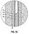
- the cables 38 may be clad in polyurethane or other protective covering 52 ( Fig. 13 ).
- the throughbores 46 in the collection of foundations sections 32 (and possibly the throughbores 48 in the platform 36), which receive the tensioning cables 38, may be filled with suitable filler material 54 that further protects the tensioning cables 38 from the negative effects of the water environment.
- the throughbores 46, 48 may be filled with a treated concrete suitable for sealing the cables 38 from the water.
- the central passageway 44 in the collection of foundation sections 32 may also be filled with concrete or other suitable filler material 56. Filling the central passageway 44 with a filler material 56 increases the overall weight of the foundation 12, further increasing the stability of the wind turbine 18 mounted to foundation 12.
- foundation 12 avoids the need to use a heavy lift crane vessel to erect the foundation 12.
- a vessel 60 having a relatively small gantry crane 62 may be sufficient to erect the foundation 12.
- the crane 62 does not have to be sized so as to lift the entire foundation 12, as in previous methodologies, but may be sized to lift the heaviest component thereof, which in the normal course is expected to be base 30.
- base 30 is much smaller in size and weight in comparison to the overall foundation 12, a much smaller crane may be utilized to assemble the foundation 12.
- the base 30 of foundation 12 may be lowered down to the seabed 14 using, for example, crane 62.
- the tensioning cables 38 have a first end 40 embedded or otherwise coupled to base 30, which is preferably done prior to the base 30 being submersed in the water 14.
- the first end of the tensioning cables 38 may be coupled to base 30 after submersion.
- the base 30 is positioned on the seabed 16 such that the tensioning cables 38 extend from the base 30 toward the surface 34.
- a second end 64 of the tensioning cables 38 may terminate adjacent surface 34.
- the second end 64 of cables 38 may be positioned above the surface 34 of the water 14. It should be recognized that prior to positioning the base 30 on seabed 16, and depending on the particular conditions of the seabed 16 at the wind turbine installation site, some preparation of the seabed 16 may have to be performed to ensure the base 30 is properly supported thereon. Such preparation techniques are generally known in the industry and will not be explained in further detail herein.
- a first foundation section 32 may be lowered through the water 14 using, for example, crane 62 and positioned on top of the base 30.
- the foundation sections 32 may include a connecting element, such as cross bar 65 extending across central passageway 44 adjacent at least one of the ends of foundation section 32.
- the connecting element is configured to cooperate with a corresponding connecting element on gantry crane 60 to allow crane 60 to move the foundation sections 32.
- the gantry crane 62 may include a hook 66 configured to engage cross bar 65 for lifting, moving or otherwise manipulating foundation sections 32.
- connecting elements may also be used to manipulate base 30.
- the tensioning cables 38 are used as a guide for guiding the foundation section 32 from a location adjacent surface 34 of the water 14 to its proper position in foundation 12 (e.g., such as beneath the surface 34 of the water 14).
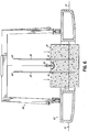
- the second ends 64 of the tensioning cables 38 may be inserted through bores 46 (i.e., threaded through bores 46) of the foundation section 32 topside (e.g., above the surface 34), such as on vessel 60 ( Fig 8 ).
- the foundation section 32 may be lowered by crane 62 into position on top of the base 30.
- the tensioning cables 38 essentially limit its movement and guide the section 32 into place.
- Such a "bead on a string” approach exemplified by the present method tremendously simplifies and increases the speed of the assembly process of foundation 12.
- another foundation section 32 may be threaded onto the tensioning cables 38 and lowered into place on top of base 30 (and on top of the prior foundation section). This process may continue until the foundation 12 is at its desired height, such as extending above the surface 34 of the water 14.
- the tensioning cables 38 as a guide for placing the foundation sections 32 provides additional benefits. For example, for purposes mentioned above and discussed further below, it is considered important that after the foundations sections 32 are stacked, the throughbores 46 of the sections 32 be substantially aligned so as to form one generally continuous conduit ( Fig 12 ).
- Using the tensioning cables 38 as a guide essentially provides a self-alignment feature such that the throughbores 46 are aligned upon placement of the foundation sections 32, i.e., the sections 32 are in essence automatically aligned as a result of the particular methodology described above. Accordingly, small, frustrating, and time-consuming adjustments to the placement of the foundation sections 32 during assembly so as to align the bores 46 of adjacent sections 32 may be avoided.
- the ends 68 of the foundation sections 32 may be shaped to facilitate seating of adjacent sections and alignment of throughbores 46.
- the ends 68 of the sections 32 may not be generally planar, but instead may be distorted or convoluted in some manner to provide an interlocking feature to the sections 32.
- Fig. 10 illustrates the ends 68 having a wavy pattern 70 (e.g., sinusoidal shape) formed therein.
- Fig. 11 illustrates the ends 68 as having alternating projections 72 and recesses 74.
- the positioning of one section relative to the other section must take on a certain orientation or configuration before the sections 32 may be successfully mated together.
- This orienting required for seating adjacent sections 32 allows the positioning of features (such as bores 46) to become predictable by virtue of the seating.
- the ends 68 may include other interlocking features, such as tongue and groove features (not shown), that prevent or minimize relative movement between two adjacent foundation sections 32.
- the foundation 12 may be assembled such that the throughbores 46 and/or the central passageways 44 of the foundation sections 32 are aligned so as to form essentially one continuous conduit along the length of the foundation 12, as illustrated in Fig. 12 . Additionally, the features described above may result in the outer surface 76 of the foundation 12 being relatively smooth.
- the platform 36 may be positioned atop the last foundation section 32.
- the tensioning cables 38 may similarly be threaded through the throughbores 48 formed therein and the platform 36 guided into place thereby. This may be done, for example, by the gantry crane 62 or by another relatively small-sized crane. In any event, the tensioning cables 38 again provide a self-alignment feature that, in essence, aligns the throughbores 48 in the platform 36 with the throughbores 46 in the foundation sections 32.
- the tensioning cables 38 may be tensioned.
- the tensioning cables 38 operate as post-tensioning elements which are tensioned after assembly of the foundation 12.
- the cables 38 may be tensioned, such as by pulling on the second ends 64 or by other known methodologies, so as compress the foundation 12 together.
- tensioning cables 38 significantly improve the strength and structural integrity of the foundation 12. Unlike many conventional post tensioning techniques, however, which impose tension at the bottom or lower end of the structure, in the present embodiment, the tension is applied at the top or upper end of the structure.
- tensioning from the upper end may be advantageous in that it may be done adjacent surface 34, such as from a surface of a vessel, instead of having to be done adjacent the seabed 16.
- the tensioning cables 38 may be tensioned and appropriately terminated so as to maintain the tension formed therein.
- the througbores 46 may be filled with treated concrete or other filler materials 54 to further protect the cables 38 from the water environment.
- a fill pipe (not shown) may be inserted into the throughbores 46 so as to dispense the fill material 54 into the throughbores 46.
- the fill material 54 is configured to have a higher density than the water such that the fill process forces the water out of the bores 46 as the bores 46 are being filled.
- the tensioning cables 38 are further protected from the corrosive or other undesirable effects of the water.
- a similar process may also be used to fill the elongate conduit formed by the plurality of aligned central passageways 44 of the foundation sections 32 with fill material 56. As noted above, this process may be utilized to increase the overall weight of the foundation 12 and thus enhance its stability.
- the wind turbine 18 may be assembled and coupled to foundation 12 in accordance with methodologies known in the art.
- the wind turbine tower 20 may be positioned on the platform 36 and securely fastened thereto by, for example, a plurality of nuts threadably coupled to corresponding throughbolts projecting from the platform 36 and extending through holes in a flange at the lower end of the tower 20.
Landscapes
- Engineering & Computer Science (AREA)
- Civil Engineering (AREA)
- Structural Engineering (AREA)
- Life Sciences & Earth Sciences (AREA)
- General Engineering & Computer Science (AREA)
- Mining & Mineral Resources (AREA)
- Paleontology (AREA)
- General Life Sciences & Earth Sciences (AREA)
- Architecture (AREA)
- Sustainable Development (AREA)
- Sustainable Energy (AREA)
- Chemical & Material Sciences (AREA)
- Combustion & Propulsion (AREA)
- Mechanical Engineering (AREA)
- Wind Motors (AREA)
Claims (15)
- Procédé d'assemblage d'une fondation (12) pour une installation d'éolienne en mer, la fondation ayant une conception modulaire incluant une base (30) et une pluralité de sections de fondation (32), le procédé comprenant :la descente de la base (30) de la fondation à travers une masse d'eau de sorte à positionner la base sur un fond marin ;l'agencement d'une pluralité d'éléments tendeurs (38) pour une post-tension de la fondation afin qu'ils s'étendent de la base jusqu'à un second emplacement positionné adjacent à une surface de la masse d'eau ;le filetage d'une extrémité (64) des éléments tendeurs (38) au second emplacement à travers des alésages (46) formés dans une section de fondation (32) et la descente vers la base (30) de sorte qu'un déplacement de la section de fondation (32) vers la base soit guidé par les éléments tendeurs (38) ; etla répétition des étapes de filetage et de descente pour empiler une pluralité de sections de fondation (32) sur la base et assembler ainsi la fondation d'éolienne.
- Procédé selon la revendication 1, dans lequel le second emplacement est au-dessus de la surface de la masse d'eau.
- Procédé selon la revendication 1 ou 2, comprenant en outre le tensionnement des éléments tendeurs (38) après avoir empilé la pluralité de sections de fondation (32) sur la base.
- Procédé selon la revendication 3, dans lequel le tensionnement des éléments tendeurs (38) se fait depuis un emplacement au-dessus de la surface de l'eau.
- Procédé selon l'une quelconque des revendications précédentes, comprenant en outre :l'utilisation des éléments tendeurs (38) pour auto-aligner les alésages (46) dans la pluralité de sections de fondation ; etle remplissage des alésages (46) avec un matériau de remplissage (54) après avoir empilé la pluralité de sections de fondation sur la base.
- Procédé selon l'une quelconque des revendications précédentes, dans lequel chacune des sections de fondation comporte une voie de passage centrale (44) à l'intérieur des alésages (46), le procédé comprenant en outre :l'utilisation des éléments tendeurs (38) pour auto-aligner les voies de passage centrales (44) dans la pluralité de sections de fondation ; etle remplissage des voies de passage centrales avec un matériau de remplissage (56) après avoir empilé la pluralité de sections de fondation sur la base.
- Procédé de construction d'une installation d'éolienne en mer, comprenant :l'assemblage d'une fondation (12) pour une éolienne selon le procédé de l'une quelconque des revendications 1 à 6 ; etle couplage d'une éolienne à la fondation.
- Procédé d'assemblage d'une fondation (12) pour une éolienne, la fondation ayant une conception modulaire incluant une base (30) et une pluralité de sections de fondation (32), le procédé comprenant :le positionnement de la base (30) de la fondation sur une surface de support ;l'agencement d'une pluralité d'éléments tendeurs (38) pour une post-tension de la fondation de sorte qu'ils s'étendent de la base (30) jusqu'à un second emplacement espacé de la base ; etl'empilement de la pluralité de sections de fondation (32) sur la base par le filetage séquentiel d'une extrémité (64) des éléments tendeurs (38) au second emplacement à travers des alésages (46) formés dans les sections de fondation (32) de sorte qu'un déplacement des sections de fondation (32) du second emplacement vers la base soit guidé par les éléments tendeurs (38).
- Procédé selon la revendication 8, comprenant en outre le tensionnement des éléments tendeurs (38) après avoir empilé la pluralité de sections de fondation (32) sur la base.
- Procédé selon la revendication 9, dans lequel le tensionnement des éléments tendeurs (38) se fait depuis une extrémité haute de la fondation.
- Procédé selon l'une quelconque des revendications 8 à 10, comprenant en outre :l'utilisation des éléments tendeurs (38) pour auto-aligner les alésages (46) dans la pluralité de sections de fondation ; etle remplissage des alésages avec un matériau de remplissage (54) après avoir empilé la pluralité de sections de fondation sur la base.
- Procédé selon l'une quelconque des revendications 8 à 11, dans lequel chacune des sections de fondation comporte une voie de passage centrale (44) à l'intérieur des alésages (46), le procédé comprenant en outre :l'utilisation des éléments tendeurs (38) pour auto-aligner les voies de passage centrales (44) dans la pluralité de sections de fondation ; etle remplissage des voies de passage centrales (44) avec un matériau de remplissage (56) après avoir empilé la pluralité de sections de fondation sur la base.
- Fondation (12) pour une installation d'éolienne en mer, comprenant une base (30) positionnée sur le fond marin d'une masse d'eau ;
une pluralité de sections de fondation (32) empilées en série les unes par-dessus les autres s'étendant jusqu'à un emplacement au-dessus de la surface de la masse d'eau ;
caractérisée en ce que :une pluralité d'éléments tendeurs (38) est prévue, chaque élément tendeur (38) ayant une première extrémité (40) noyée de façon permanente au sein de la base (30) et une seconde extrémité (64) adjacente à une surface de la masse d'eau, les éléments tendeurs étant tendus pour comprimer la fondation ; etchaque section de fondation (32) ayant une pluralité d'alésages (46) dont chacun reçoit un élément tendeur respectif de la pluralité d'éléments tendeurs (38) au travers. - Fondation selon la revendication 13, dans laquelle la base (30) comporte une dimension transversale supérieure à la dimension transversale de la pluralité de sections de fondation.
- Fondation selon la revendication 13 ou 14, dans laquelle les sections de fondation ont des extrémités (68), les extrémités en face de sections de fondation adjacentes (32) ayant des interfaces non planes qui coopèrent de sorte à orienter une section de fondation par rapport à sa section de fondation adjacente.
Applications Claiming Priority (3)
| Application Number | Priority Date | Filing Date | Title |
|---|---|---|---|
| US39487310P | 2010-10-20 | 2010-10-20 | |
| DKPA201070519 | 2010-11-29 | ||
| PCT/DK2011/050395 WO2012052029A1 (fr) | 2010-10-20 | 2011-10-18 | Fondation pour une éolienne et procédé de fabrication de celle-ci |
Publications (2)
| Publication Number | Publication Date |
|---|---|
| EP2630307A1 EP2630307A1 (fr) | 2013-08-28 |
| EP2630307B1 true EP2630307B1 (fr) | 2016-09-21 |
Family
ID=44883035
Family Applications (1)
| Application Number | Title | Priority Date | Filing Date |
|---|---|---|---|
| EP11776076.9A Not-in-force EP2630307B1 (fr) | 2010-10-20 | 2011-10-18 | Fondation pour une éolienne et procédé de fabrication de celle-ci |
Country Status (6)
| Country | Link |
|---|---|
| US (1) | US10107265B2 (fr) |
| EP (1) | EP2630307B1 (fr) |
| CN (1) | CN103492644B (fr) |
| DK (1) | DK2630307T3 (fr) |
| PT (1) | PT2630307T (fr) |
| WO (1) | WO2012052029A1 (fr) |
Families Citing this family (17)
| Publication number | Priority date | Publication date | Assignee | Title |
|---|---|---|---|---|
| ES2396087B1 (es) | 2011-06-30 | 2014-05-19 | Acciona Windpower, S.A. | Procedimiento de montaje de un aerogenerador y aerogenerador montado según dicho procedimiento |
| WO2013074008A1 (fr) * | 2011-11-18 | 2013-05-23 | Telefonaktiebolaget L M Ericsson (Publ) | Procédé et agencements ayant trait à un mât d'antenne d'un système de communication sans fil |
| US9175670B2 (en) * | 2012-08-03 | 2015-11-03 | James D. Lockwood | Precast concrete post tensioned segmented wind turbine tower |
| KR101447108B1 (ko) * | 2012-09-20 | 2014-10-06 | 한국해양과학기술원 | 해상풍력 지지구조 |
| EP2963183A1 (fr) * | 2014-06-30 | 2016-01-06 | Siemens Aktiengesellschaft | Structure de support en mer, installation de tour en mer avec ladite structure et installation d'énergie éolienne en mer avec l'installation de tour de forage en mer |
| UA122866C2 (uk) * | 2014-10-30 | 2021-01-13 | Біо Тауерс, С.Л. | Спосіб встановлення порожнистої бетонної вежі, виготовленої із більш ніж одного сегмента, і відповідна порожниста бетонна вежа |
| MX2018002590A (es) | 2015-08-31 | 2018-11-09 | Wind Tower Tech Llc | Sistema y metodo para instalar un tendon tensado en una torre de turbina de viento. |
| CA2916228C (fr) * | 2015-12-23 | 2019-02-26 | 649119 N.B. Inc. | Fondation de beton prefabriquee d'une construction modulaire destinee a une tour de telecommunication ou une tour d'eolienne |
| ES2911709T3 (es) * | 2016-02-26 | 2022-05-20 | Nordex Energy Spain S A | Procedimiento de fabricación de torres de hormigón para aerogeneradores |
| DK3312416T3 (da) * | 2016-10-24 | 2022-07-25 | Nordex Energy Spain S A | Vindmølletårn på fundament |
| NL2019045B1 (en) * | 2017-06-09 | 2018-12-17 | Delft Offshore Turbine B V | Wind turbine generator with hydraulic pump |
| DE102018131443A1 (de) * | 2018-12-07 | 2020-06-10 | Wobben Properties Gmbh | Fundamentanordnung, Adapterelement, Spannvorrichtung und Turm einer Windenergieanlage sowie Verfahren zum Vorspannen eines Turms einer Windenergieanlage |
| DE102019111430A1 (de) * | 2019-05-03 | 2020-11-05 | Innogy Se | Verbindung bei Gründungen |
| EP4284980B1 (fr) * | 2021-01-27 | 2024-11-13 | Elomatic Oy | Fondation pour une structure en mer et procédé d'installation d'une fondation |
| US20230296080A1 (en) * | 2022-03-16 | 2023-09-21 | Oil States Industries, Inc. | Offshore column tension leg platform |
| CN115573397B (zh) * | 2022-09-23 | 2023-05-09 | 上海勘测设计研究院有限公司 | 海上风电桩基土塞挤土效应的评估模型设计及评估方法 |
| US12179890B2 (en) | 2022-10-31 | 2024-12-31 | Oil States Industries, Inc. | Offshore platform with vertical column assembly |
Citations (2)
| Publication number | Priority date | Publication date | Assignee | Title |
|---|---|---|---|---|
| DE10100047A1 (de) * | 2001-01-02 | 2002-07-04 | Bruno Gruber | Verfahren zur Erstellung eines Turmes auf einem Gewässerboden |
| GB2410757A (en) * | 2004-02-04 | 2005-08-10 | Abb Offshore Systems Ltd | Underwater Installation Apparatus |
Family Cites Families (35)
| Publication number | Priority date | Publication date | Assignee | Title |
|---|---|---|---|---|
| US3803855A (en) * | 1972-09-29 | 1974-04-16 | A Malkiel | Submerged oil storage tank |
| US4563852A (en) * | 1984-12-21 | 1986-01-14 | Irving Achtenberg | Method of reinforcing concrete block foundation walls |
| JP2000283019A (ja) | 1999-03-31 | 2000-10-10 | Pc Bridge Co Ltd | コンクリート製風車支持タワー及びその構築方法 |
| AU2001242321A1 (en) | 2000-03-28 | 2001-10-08 | Per Lauritsen | Floating offshore wind power installation |
| WO2002027105A1 (fr) * | 2000-09-27 | 2002-04-04 | Allan P Henderson | Fondation a lestage peripherique pour eoliennes et analogues |
| NO322927B1 (no) * | 2001-02-13 | 2006-12-18 | Hammerfest Strom As | Anordning for produksjon av energi fra strommer i vannmasser, en forankring, samt fremgangsmate for installasjon av anordningen |
| NL1019953C2 (nl) * | 2002-02-12 | 2002-12-19 | Mecal Applied Mechanics B V | Geprefabriceerde toren of mast, alsmede een methode voor het samenvoegen en/of naspannen van segmenten die één constructie moeten vormen, alsmede een werkwijze voor het opbouwen van een toren of mast bestaande uit segmenten. |
| JP2003257187A (ja) | 2002-02-28 | 2003-09-12 | Hitachi Ltd | 不揮発性メモリ、icカード及びデータ処理装置 |
| GB2423108C (en) * | 2002-10-23 | 2007-03-29 | Engineering Business Ltd | Mounting of offshore structures |
| WO2004061302A2 (fr) * | 2003-01-06 | 2004-07-22 | Vestas Wind Systems A/S | Eolienne a fondation flottante |
| US7293960B2 (en) * | 2003-10-23 | 2007-11-13 | Shigeyuki Yamamoto | Power generation assemblies, and apparatus for use therewith |
| JP4113110B2 (ja) * | 2003-12-22 | 2008-07-09 | 三井住友建設株式会社 | コンクリートタワー |
| NO321085B1 (no) * | 2004-04-02 | 2006-03-13 | Asbjorn Skotte | Bolgekraftverk. |
| US20080240864A1 (en) * | 2007-04-02 | 2008-10-02 | Ups Wind Management , Llc | Assembly, transportation and installation of deepwater windpower plant |
| US7674073B2 (en) | 2007-04-19 | 2010-03-09 | Conocophillips Company | Modular concrete substructures |
| CN101809283B (zh) * | 2007-08-29 | 2012-07-25 | 维斯塔斯风力系统集团公司 | 用于离岸风力发电机的单桩地基 |
| CA2699380A1 (fr) * | 2007-09-13 | 2009-03-19 | Floating Windfarms Corporation | Eolienne a axe vertical au large, systemes et procedes associes |
| US7612462B2 (en) * | 2007-10-08 | 2009-11-03 | Viterna Larry A | Floating wind turbine system |
| DK2238347T3 (en) * | 2007-12-21 | 2018-10-29 | Vestas Wind Sys As | A WINDMILL, A PROCEDURE FOR REDUCING NOISE MISSION FROM A WINDMILL TOWER AND USING A WINDMILL |
| PL2727813T3 (pl) * | 2008-04-23 | 2018-07-31 | Principle Power, Inc. | Stabilizowana za pomocą kolumn platforma morska z płytami tłumiącymi typu pułapka wodna i asymetrycznym systemem cumowniczym podtrzymująca morskie turbiny wiatrowe |
| WO2010003416A1 (fr) * | 2008-07-09 | 2010-01-14 | Foot Foundation A/S | Construction en mer |
| US8169099B2 (en) * | 2008-08-18 | 2012-05-01 | Samuel Roznitsky | Deep offshore floating wind turbine and method of deep offshore floating wind turbine assembly, transportation, installation and operation |
| CA2747541C (fr) * | 2008-12-18 | 2017-07-11 | Single Buoy Moorings Inc. | Eoliennes de haute mer amovibles dotees d'un systeme d'amarrage installe au prealable |
| US20100164230A1 (en) * | 2008-12-29 | 2010-07-01 | Sidney Irving Belinsky | Installation for harvesting ocean currents (IHOC) and methods and means for its delivery, installation and servicing |
| EP2272754A1 (fr) * | 2009-06-30 | 2011-01-12 | Vestas Wind Systems A/S | Installation d'éoliennes par dirigeable |
| US20100132270A1 (en) * | 2009-07-08 | 2010-06-03 | General Electric Wind Energy & Energy Services | Modular surface foundation for wind turbine space frame towers |
| US8240955B2 (en) * | 2010-06-29 | 2012-08-14 | General Electric Company | Tower segments and method for off-shore wind turbines |
| US20110138704A1 (en) * | 2010-06-30 | 2011-06-16 | General Electric Company | Tower with tensioning cables |
| US8544214B2 (en) * | 2010-12-07 | 2013-10-01 | General Electric Company | Wind turbine tower assembly and method for assembling the same |
| ES2396087B1 (es) * | 2011-06-30 | 2014-05-19 | Acciona Windpower, S.A. | Procedimiento de montaje de un aerogenerador y aerogenerador montado según dicho procedimiento |
| WO2013074008A1 (fr) * | 2011-11-18 | 2013-05-23 | Telefonaktiebolaget L M Ericsson (Publ) | Procédé et agencements ayant trait à un mât d'antenne d'un système de communication sans fil |
| US9175670B2 (en) * | 2012-08-03 | 2015-11-03 | James D. Lockwood | Precast concrete post tensioned segmented wind turbine tower |
| KR101447108B1 (ko) * | 2012-09-20 | 2014-10-06 | 한국해양과학기술원 | 해상풍력 지지구조 |
| EP2963183A1 (fr) * | 2014-06-30 | 2016-01-06 | Siemens Aktiengesellschaft | Structure de support en mer, installation de tour en mer avec ladite structure et installation d'énergie éolienne en mer avec l'installation de tour de forage en mer |
| CA2916228C (fr) * | 2015-12-23 | 2019-02-26 | 649119 N.B. Inc. | Fondation de beton prefabriquee d'une construction modulaire destinee a une tour de telecommunication ou une tour d'eolienne |
-
2011
- 2011-10-18 EP EP11776076.9A patent/EP2630307B1/fr not_active Not-in-force
- 2011-10-18 PT PT117760769T patent/PT2630307T/pt unknown
- 2011-10-18 CN CN201180050813.6A patent/CN103492644B/zh not_active Expired - Fee Related
- 2011-10-18 US US13/880,649 patent/US10107265B2/en active Active
- 2011-10-18 WO PCT/DK2011/050395 patent/WO2012052029A1/fr not_active Ceased
- 2011-10-18 DK DK11776076.9T patent/DK2630307T3/en active
Patent Citations (2)
| Publication number | Priority date | Publication date | Assignee | Title |
|---|---|---|---|---|
| DE10100047A1 (de) * | 2001-01-02 | 2002-07-04 | Bruno Gruber | Verfahren zur Erstellung eines Turmes auf einem Gewässerboden |
| GB2410757A (en) * | 2004-02-04 | 2005-08-10 | Abb Offshore Systems Ltd | Underwater Installation Apparatus |
Also Published As
| Publication number | Publication date |
|---|---|
| EP2630307A1 (fr) | 2013-08-28 |
| DK2630307T3 (en) | 2016-11-21 |
| PT2630307T (pt) | 2016-10-27 |
| US20140044554A1 (en) | 2014-02-13 |
| CN103492644A (zh) | 2014-01-01 |
| WO2012052029A1 (fr) | 2012-04-26 |
| US10107265B2 (en) | 2018-10-23 |
| CN103492644B (zh) | 2015-12-16 |
Similar Documents
| Publication | Publication Date | Title |
|---|---|---|
| US10107265B2 (en) | Foundation for a wind turbine and method of making same | |
| JP5274329B2 (ja) | 洋上風力発電設備及びその施工方法 | |
| US11352098B2 (en) | Method of assembling a floating wind turbine platform | |
| JP5330048B2 (ja) | 洋上風力発電設備の施工方法 | |
| KR102155394B1 (ko) | 부체식 해상 풍력발전 설비 | |
| EP1583907B1 (fr) | Eolienne a fondation flottante | |
| JP5738643B2 (ja) | 洋上風力発電設備の施工方法 | |
| JP2010223114A5 (fr) | ||
| EP3899260B1 (fr) | Support d'éolienne flottante | |
| CN106687368A (zh) | 用于风力涡轮机的浮动基础结构以及其安装方法 | |
| US20180030962A1 (en) | Offshore deployable floating wind turbine system and method | |
| CN101939537A (zh) | 离岸垂直轴风力涡轮机及相关联系统及方法 | |
| EP2662497A1 (fr) | Fondation d'éolienne | |
| US20180030961A1 (en) | Offshore deployable wind turbine system and method with a gravity base | |
| WO2018018103A1 (fr) | Système et procédé d'éolienne déployable en mer avec une base à gravité | |
| WO2018018104A1 (fr) | Système et procédé d'éolienne flottante déployable en mer | |
| JP6937627B2 (ja) | 洋上風力発電設備及びその施工方法 | |
| JP7492283B1 (ja) | 着床式洋上架台の構築方法、着床式洋上架台、及び洋上風力発電装置 | |
| US20240084537A1 (en) | Portal frame platform and construction method for large offshore wind turbines | |
| JP2024179238A (ja) | スパー型洋上風力発電設備の建造方法 |
Legal Events
| Date | Code | Title | Description |
|---|---|---|---|
| PUAI | Public reference made under article 153(3) epc to a published international application that has entered the european phase |
Free format text: ORIGINAL CODE: 0009012 |
|
| 17P | Request for examination filed |
Effective date: 20130419 |
|
| AK | Designated contracting states |
Kind code of ref document: A1 Designated state(s): AL AT BE BG CH CY CZ DE DK EE ES FI FR GB GR HR HU IE IS IT LI LT LU LV MC MK MT NL NO PL PT RO RS SE SI SK SM TR |
|
| DAX | Request for extension of the european patent (deleted) | ||
| RAP1 | Party data changed (applicant data changed or rights of an application transferred) |
Owner name: MHI VESTAS OFFSHORE WIND A/S |
|
| 17Q | First examination report despatched |
Effective date: 20150218 |
|
| REG | Reference to a national code |
Ref country code: DE Ref legal event code: R079 Ref document number: 602011030596 Country of ref document: DE Free format text: PREVIOUS MAIN CLASS: E02D0027520000 Ipc: E02D0027420000 |
|
| GRAP | Despatch of communication of intention to grant a patent |
Free format text: ORIGINAL CODE: EPIDOSNIGR1 |
|
| RIC1 | Information provided on ipc code assigned before grant |
Ipc: E02D 27/42 20060101AFI20160321BHEP Ipc: E04H 12/34 20060101ALI20160321BHEP |
|
| INTG | Intention to grant announced |
Effective date: 20160414 |
|
| GRAS | Grant fee paid |
Free format text: ORIGINAL CODE: EPIDOSNIGR3 |
|
| GRAA | (expected) grant |
Free format text: ORIGINAL CODE: 0009210 |
|
| AK | Designated contracting states |
Kind code of ref document: B1 Designated state(s): AL AT BE BG CH CY CZ DE DK EE ES FI FR GB GR HR HU IE IS IT LI LT LU LV MC MK MT NL NO PL PT RO RS SE SI SK SM TR |
|
| REG | Reference to a national code |
Ref country code: GB Ref legal event code: FG4D |
|
| REG | Reference to a national code |
Ref country code: CH Ref legal event code: EP |
|
| REG | Reference to a national code |
Ref country code: FR Ref legal event code: PLFP Year of fee payment: 6 |
|
| REG | Reference to a national code |
Ref country code: AT Ref legal event code: REF Ref document number: 831176 Country of ref document: AT Kind code of ref document: T Effective date: 20161015 |
|
| REG | Reference to a national code |
Ref country code: IE Ref legal event code: FG4D |
|
| REG | Reference to a national code |
Ref country code: PT Ref legal event code: SC4A Ref document number: 2630307 Country of ref document: PT Date of ref document: 20161027 Kind code of ref document: T Free format text: AVAILABILITY OF NATIONAL TRANSLATION Effective date: 20161020 |
|
| REG | Reference to a national code |
Ref country code: NL Ref legal event code: FP |
|
| REG | Reference to a national code |
Ref country code: DE Ref legal event code: R096 Ref document number: 602011030596 Country of ref document: DE |
|
| REG | Reference to a national code |
Ref country code: DK Ref legal event code: T3 Effective date: 20161117 |
|
| REG | Reference to a national code |
Ref country code: LT Ref legal event code: MG4D |
|
| PG25 | Lapsed in a contracting state [announced via postgrant information from national office to epo] |
Ref country code: LT Free format text: LAPSE BECAUSE OF FAILURE TO SUBMIT A TRANSLATION OF THE DESCRIPTION OR TO PAY THE FEE WITHIN THE PRESCRIBED TIME-LIMIT Effective date: 20160921 Ref country code: RS Free format text: LAPSE BECAUSE OF FAILURE TO SUBMIT A TRANSLATION OF THE DESCRIPTION OR TO PAY THE FEE WITHIN THE PRESCRIBED TIME-LIMIT Effective date: 20160921 Ref country code: NO Free format text: LAPSE BECAUSE OF FAILURE TO SUBMIT A TRANSLATION OF THE DESCRIPTION OR TO PAY THE FEE WITHIN THE PRESCRIBED TIME-LIMIT Effective date: 20161221 Ref country code: FI Free format text: LAPSE BECAUSE OF FAILURE TO SUBMIT A TRANSLATION OF THE DESCRIPTION OR TO PAY THE FEE WITHIN THE PRESCRIBED TIME-LIMIT Effective date: 20160921 |
|
| REG | Reference to a national code |
Ref country code: AT Ref legal event code: MK05 Ref document number: 831176 Country of ref document: AT Kind code of ref document: T Effective date: 20160921 |
|
| PG25 | Lapsed in a contracting state [announced via postgrant information from national office to epo] |
Ref country code: SE Free format text: LAPSE BECAUSE OF FAILURE TO SUBMIT A TRANSLATION OF THE DESCRIPTION OR TO PAY THE FEE WITHIN THE PRESCRIBED TIME-LIMIT Effective date: 20160921 Ref country code: LV Free format text: LAPSE BECAUSE OF FAILURE TO SUBMIT A TRANSLATION OF THE DESCRIPTION OR TO PAY THE FEE WITHIN THE PRESCRIBED TIME-LIMIT Effective date: 20160921 Ref country code: GR Free format text: LAPSE BECAUSE OF FAILURE TO SUBMIT A TRANSLATION OF THE DESCRIPTION OR TO PAY THE FEE WITHIN THE PRESCRIBED TIME-LIMIT Effective date: 20161222 |
|
| PG25 | Lapsed in a contracting state [announced via postgrant information from national office to epo] |
Ref country code: RO Free format text: LAPSE BECAUSE OF FAILURE TO SUBMIT A TRANSLATION OF THE DESCRIPTION OR TO PAY THE FEE WITHIN THE PRESCRIBED TIME-LIMIT Effective date: 20160921 Ref country code: EE Free format text: LAPSE BECAUSE OF FAILURE TO SUBMIT A TRANSLATION OF THE DESCRIPTION OR TO PAY THE FEE WITHIN THE PRESCRIBED TIME-LIMIT Effective date: 20160921 |
|
| PG25 | Lapsed in a contracting state [announced via postgrant information from national office to epo] |
Ref country code: BG Free format text: LAPSE BECAUSE OF FAILURE TO SUBMIT A TRANSLATION OF THE DESCRIPTION OR TO PAY THE FEE WITHIN THE PRESCRIBED TIME-LIMIT Effective date: 20161221 Ref country code: PL Free format text: LAPSE BECAUSE OF FAILURE TO SUBMIT A TRANSLATION OF THE DESCRIPTION OR TO PAY THE FEE WITHIN THE PRESCRIBED TIME-LIMIT Effective date: 20160921 Ref country code: SM Free format text: LAPSE BECAUSE OF FAILURE TO SUBMIT A TRANSLATION OF THE DESCRIPTION OR TO PAY THE FEE WITHIN THE PRESCRIBED TIME-LIMIT Effective date: 20160921 Ref country code: ES Free format text: LAPSE BECAUSE OF FAILURE TO SUBMIT A TRANSLATION OF THE DESCRIPTION OR TO PAY THE FEE WITHIN THE PRESCRIBED TIME-LIMIT Effective date: 20160921 Ref country code: IS Free format text: LAPSE BECAUSE OF FAILURE TO SUBMIT A TRANSLATION OF THE DESCRIPTION OR TO PAY THE FEE WITHIN THE PRESCRIBED TIME-LIMIT Effective date: 20170121 Ref country code: SK Free format text: LAPSE BECAUSE OF FAILURE TO SUBMIT A TRANSLATION OF THE DESCRIPTION OR TO PAY THE FEE WITHIN THE PRESCRIBED TIME-LIMIT Effective date: 20160921 Ref country code: AT Free format text: LAPSE BECAUSE OF FAILURE TO SUBMIT A TRANSLATION OF THE DESCRIPTION OR TO PAY THE FEE WITHIN THE PRESCRIBED TIME-LIMIT Effective date: 20160921 Ref country code: CZ Free format text: LAPSE BECAUSE OF FAILURE TO SUBMIT A TRANSLATION OF THE DESCRIPTION OR TO PAY THE FEE WITHIN THE PRESCRIBED TIME-LIMIT Effective date: 20160921 |
|
| REG | Reference to a national code |
Ref country code: CH Ref legal event code: PL |
|
| REG | Reference to a national code |
Ref country code: DE Ref legal event code: R097 Ref document number: 602011030596 Country of ref document: DE |
|
| PG25 | Lapsed in a contracting state [announced via postgrant information from national office to epo] |
Ref country code: IT Free format text: LAPSE BECAUSE OF FAILURE TO SUBMIT A TRANSLATION OF THE DESCRIPTION OR TO PAY THE FEE WITHIN THE PRESCRIBED TIME-LIMIT Effective date: 20160921 |
|
| REG | Reference to a national code |
Ref country code: IE Ref legal event code: MM4A |
|
| PLBE | No opposition filed within time limit |
Free format text: ORIGINAL CODE: 0009261 |
|
| STAA | Information on the status of an ep patent application or granted ep patent |
Free format text: STATUS: NO OPPOSITION FILED WITHIN TIME LIMIT |
|
| PG25 | Lapsed in a contracting state [announced via postgrant information from national office to epo] |
Ref country code: LI Free format text: LAPSE BECAUSE OF NON-PAYMENT OF DUE FEES Effective date: 20161031 Ref country code: CH Free format text: LAPSE BECAUSE OF NON-PAYMENT OF DUE FEES Effective date: 20161031 |
|
| 26N | No opposition filed |
Effective date: 20170622 |
|
| PG25 | Lapsed in a contracting state [announced via postgrant information from national office to epo] |
Ref country code: LU Free format text: LAPSE BECAUSE OF NON-PAYMENT OF DUE FEES Effective date: 20161018 |
|
| REG | Reference to a national code |
Ref country code: FR Ref legal event code: PLFP Year of fee payment: 7 |
|
| PG25 | Lapsed in a contracting state [announced via postgrant information from national office to epo] |
Ref country code: SI Free format text: LAPSE BECAUSE OF FAILURE TO SUBMIT A TRANSLATION OF THE DESCRIPTION OR TO PAY THE FEE WITHIN THE PRESCRIBED TIME-LIMIT Effective date: 20160921 Ref country code: IE Free format text: LAPSE BECAUSE OF NON-PAYMENT OF DUE FEES Effective date: 20161018 |
|
| PG25 | Lapsed in a contracting state [announced via postgrant information from national office to epo] |
Ref country code: CY Free format text: LAPSE BECAUSE OF FAILURE TO SUBMIT A TRANSLATION OF THE DESCRIPTION OR TO PAY THE FEE WITHIN THE PRESCRIBED TIME-LIMIT Effective date: 20160921 Ref country code: HU Free format text: LAPSE BECAUSE OF FAILURE TO SUBMIT A TRANSLATION OF THE DESCRIPTION OR TO PAY THE FEE WITHIN THE PRESCRIBED TIME-LIMIT; INVALID AB INITIO Effective date: 20111018 |
|
| PG25 | Lapsed in a contracting state [announced via postgrant information from national office to epo] |
Ref country code: HR Free format text: LAPSE BECAUSE OF FAILURE TO SUBMIT A TRANSLATION OF THE DESCRIPTION OR TO PAY THE FEE WITHIN THE PRESCRIBED TIME-LIMIT Effective date: 20160921 Ref country code: MC Free format text: LAPSE BECAUSE OF FAILURE TO SUBMIT A TRANSLATION OF THE DESCRIPTION OR TO PAY THE FEE WITHIN THE PRESCRIBED TIME-LIMIT Effective date: 20160921 Ref country code: MK Free format text: LAPSE BECAUSE OF FAILURE TO SUBMIT A TRANSLATION OF THE DESCRIPTION OR TO PAY THE FEE WITHIN THE PRESCRIBED TIME-LIMIT Effective date: 20160921 Ref country code: MT Free format text: LAPSE BECAUSE OF NON-PAYMENT OF DUE FEES Effective date: 20161031 |
|
| REG | Reference to a national code |
Ref country code: FR Ref legal event code: PLFP Year of fee payment: 8 |
|
| PG25 | Lapsed in a contracting state [announced via postgrant information from national office to epo] |
Ref country code: TR Free format text: LAPSE BECAUSE OF FAILURE TO SUBMIT A TRANSLATION OF THE DESCRIPTION OR TO PAY THE FEE WITHIN THE PRESCRIBED TIME-LIMIT Effective date: 20160921 Ref country code: AL Free format text: LAPSE BECAUSE OF FAILURE TO SUBMIT A TRANSLATION OF THE DESCRIPTION OR TO PAY THE FEE WITHIN THE PRESCRIBED TIME-LIMIT Effective date: 20160921 |
|
| PGFP | Annual fee paid to national office [announced via postgrant information from national office to epo] |
Ref country code: PT Payment date: 20201006 Year of fee payment: 10 |
|
| REG | Reference to a national code |
Ref country code: DE Ref legal event code: R081 Ref document number: 602011030596 Country of ref document: DE Owner name: VESTAS WIND SYSTEMS A/S, DK Free format text: FORMER OWNER: MHI VESTAS OFFSHORE WIND A/S, AARHUS, DK Ref country code: DE Ref legal event code: R081 Ref document number: 602011030596 Country of ref document: DE Owner name: VESTAS OFFSHORE WIND A/S, DK Free format text: FORMER OWNER: MHI VESTAS OFFSHORE WIND A/S, AARHUS, DK |
|
| REG | Reference to a national code |
Ref country code: NL Ref legal event code: HC Owner name: VESTAS OFFSHORE WIND A/S; DK Free format text: DETAILS ASSIGNMENT: CHANGE OF OWNER(S), CHANGE OF OWNER(S) NAME; FORMER OWNER NAME: MHI VESTAS OFFSHORE WIND A/S Effective date: 20210618 |
|
| REG | Reference to a national code |
Ref country code: BE Ref legal event code: HC Owner name: VESTAS OFFSHORE WIND A/S; DK Free format text: DETAILS ASSIGNMENT: CHANGE OF OWNER(S), CHANGE OF OWNER(S) NAME; FORMER OWNER NAME: MHI VESTAS OFFSHORE WIND A/S Effective date: 20210714 |
|
| REG | Reference to a national code |
Ref country code: GB Ref legal event code: 732E Free format text: REGISTERED BETWEEN 20211125 AND 20211201 |
|
| REG | Reference to a national code |
Ref country code: BE Ref legal event code: PD Owner name: VESTAS WIND SYSTEMS A/S; DK Free format text: DETAILS ASSIGNMENT: CHANGE OF OWNER(S), ASSIGNMENT; FORMER OWNER NAME: VESTAS OFFSHORE WIND A/S Effective date: 20220311 |
|
| REG | Reference to a national code |
Ref country code: NL Ref legal event code: PD Owner name: VESTAS WIND SYSTEMS A/S; DK Free format text: DETAILS ASSIGNMENT: CHANGE OF OWNER(S), ASSIGNMENT; FORMER OWNER NAME: VESTAS OFFSHORE WIND A/S Effective date: 20220321 |
|
| REG | Reference to a national code |
Ref country code: DE Ref legal event code: R081 Ref document number: 602011030596 Country of ref document: DE Owner name: VESTAS WIND SYSTEMS A/S, DK Free format text: FORMER OWNER: VESTAS OFFSHORE WIND A/S, AARHUS, DK |
|
| PG25 | Lapsed in a contracting state [announced via postgrant information from national office to epo] |
Ref country code: PT Free format text: LAPSE BECAUSE OF NON-PAYMENT OF DUE FEES Effective date: 20220418 |
|
| PGFP | Annual fee paid to national office [announced via postgrant information from national office to epo] |
Ref country code: NL Payment date: 20221025 Year of fee payment: 12 Ref country code: FR Payment date: 20221024 Year of fee payment: 12 |
|
| PGFP | Annual fee paid to national office [announced via postgrant information from national office to epo] |
Ref country code: GB Payment date: 20221018 Year of fee payment: 12 Ref country code: DK Payment date: 20221024 Year of fee payment: 12 Ref country code: DE Payment date: 20221028 Year of fee payment: 12 |
|
| PGFP | Annual fee paid to national office [announced via postgrant information from national office to epo] |
Ref country code: BE Payment date: 20221025 Year of fee payment: 12 |
|
| REG | Reference to a national code |
Ref country code: DE Ref legal event code: R119 Ref document number: 602011030596 Country of ref document: DE |
|
| REG | Reference to a national code |
Ref country code: DK Ref legal event code: EBP Effective date: 20231031 |
|
| REG | Reference to a national code |
Ref country code: NL Ref legal event code: MM Effective date: 20231101 |
|
| REG | Reference to a national code |
Ref country code: BE Ref legal event code: MM Effective date: 20231031 |
|
| GBPC | Gb: european patent ceased through non-payment of renewal fee |
Effective date: 20231018 |
|
| PG25 | Lapsed in a contracting state [announced via postgrant information from national office to epo] |
Ref country code: GB Free format text: LAPSE BECAUSE OF NON-PAYMENT OF DUE FEES Effective date: 20231018 |
|
| PG25 | Lapsed in a contracting state [announced via postgrant information from national office to epo] |
Ref country code: NL Free format text: LAPSE BECAUSE OF NON-PAYMENT OF DUE FEES Effective date: 20231101 |
|
| PG25 | Lapsed in a contracting state [announced via postgrant information from national office to epo] |
Ref country code: NL Free format text: LAPSE BECAUSE OF NON-PAYMENT OF DUE FEES Effective date: 20231101 Ref country code: GB Free format text: LAPSE BECAUSE OF NON-PAYMENT OF DUE FEES Effective date: 20231018 Ref country code: FR Free format text: LAPSE BECAUSE OF NON-PAYMENT OF DUE FEES Effective date: 20231031 Ref country code: DE Free format text: LAPSE BECAUSE OF NON-PAYMENT OF DUE FEES Effective date: 20240501 |
|
| PG25 | Lapsed in a contracting state [announced via postgrant information from national office to epo] |
Ref country code: BE Free format text: LAPSE BECAUSE OF NON-PAYMENT OF DUE FEES Effective date: 20231031 |
|
| PG25 | Lapsed in a contracting state [announced via postgrant information from national office to epo] |
Ref country code: DK Free format text: LAPSE BECAUSE OF NON-PAYMENT OF DUE FEES Effective date: 20231031 |
|
| PG25 | Lapsed in a contracting state [announced via postgrant information from national office to epo] |
Ref country code: DK Free format text: LAPSE BECAUSE OF NON-PAYMENT OF DUE FEES Effective date: 20231031 |