EP2630876A2 - Insert d'objet et procédé de fonctionnement d'un insert d'objet de l'industrie de traitement du tabac - Google Patents
Insert d'objet et procédé de fonctionnement d'un insert d'objet de l'industrie de traitement du tabac Download PDFInfo
- Publication number
- EP2630876A2 EP2630876A2 EP13155376.0A EP13155376A EP2630876A2 EP 2630876 A2 EP2630876 A2 EP 2630876A2 EP 13155376 A EP13155376 A EP 13155376A EP 2630876 A2 EP2630876 A2 EP 2630876A2
- Authority
- EP
- European Patent Office
- Prior art keywords
- objects
- defective
- strand
- inserter
- processing industry
- Prior art date
- Legal status (The legal status is an assumption and is not a legal conclusion. Google has not performed a legal analysis and makes no representation as to the accuracy of the status listed.)
- Withdrawn
Links
Images

Classifications
-
- A—HUMAN NECESSITIES
- A24—TOBACCO; CIGARS; CIGARETTES; SIMULATED SMOKING DEVICES; SMOKERS' REQUISITES
- A24D—CIGARS; CIGARETTES; TOBACCO SMOKE FILTERS; MOUTHPIECES OF CIGARS OR CIGARETTES; MANUFACTURE OF TOBACCO SMOKE FILTERS OR MOUTHPIECES
- A24D3/00—Tobacco smoke filters, e.g. filter tips or filtering inserts; Filters specially adapted for simulated smoking devices; Mouthpieces of cigars or cigarettes
- A24D3/02—Manufacture of tobacco smoke filters
- A24D3/0204—Preliminary operations before the filter rod forming process, e.g. crimping, blooming
- A24D3/0212—Applying additives to filter materials
- A24D3/0216—Applying additives to filter materials the additive being in the form of capsules, beads or the like
-
- B—PERFORMING OPERATIONS; TRANSPORTING
- B07—SEPARATING SOLIDS FROM SOLIDS; SORTING
- B07C—POSTAL SORTING; SORTING INDIVIDUAL ARTICLES, OR BULK MATERIAL FIT TO BE SORTED PIECE-MEAL, e.g. BY PICKING
- B07C5/00—Sorting according to a characteristic or feature of the articles or material being sorted, e.g. by control effected by devices which detect or measure such characteristic or feature; Sorting by manually actuated devices, e.g. switches
- B07C5/04—Sorting according to size
- B07C5/10—Sorting according to size measured by light-responsive means
-
- B—PERFORMING OPERATIONS; TRANSPORTING
- B07—SEPARATING SOLIDS FROM SOLIDS; SORTING
- B07C—POSTAL SORTING; SORTING INDIVIDUAL ARTICLES, OR BULK MATERIAL FIT TO BE SORTED PIECE-MEAL, e.g. BY PICKING
- B07C5/00—Sorting according to a characteristic or feature of the articles or material being sorted, e.g. by control effected by devices which detect or measure such characteristic or feature; Sorting by manually actuated devices, e.g. switches
- B07C5/36—Sorting apparatus characterised by the means used for distribution
- B07C5/363—Sorting apparatus characterised by the means used for distribution by means of air
Definitions
- the invention relates to a method for operating an object inserter of the tobacco-processing industry.
- the invention further relates to an object inlay of the tobacco processing industry.
- strands of the tobacco processing industry such as filter strands or tobacco rods, which serve to produce high quality filter rods or tobacco sticks
- objects in the strand to the properties of the product produced, for example Filter cigarettes, influence.
- filter rods in a strand process it may be desirable to introduce several objects into the filter rods cut to length from the filter rod, which usually have a multiple use length. For example, with a filter rod of four times the length of use, four capsules may be provided introduced, which are filled with liquid, for example, a menthol-containing liquid.
- the filter rods produced four times the length of use with four inserted capsules are cut in the further process for the production of filter rods, for example, four filter rods simple use length, so that each filter, which is combined with a cigarette stick containing a corresponding capsule.
- a capsule it is also possible to introduce another object, such as, for example, an activated charcoal granulate pellet or another object, preferably of a predetermined shape, such as, for example, a cut extrudate.
- German patent application of the applicant with the file number DE 10 2011 082 309.3 It is known to screen out defective liquid capsules from a stream of liquid capsules provided upstream of supplying the liquid capsules to a product of the tobacco processing industry, conveying the stream of liquid capsules on a conveying path, wherein light is in a recording area on at least one liquid capsule is directed and determined on the basis of a recorded by the at least one illuminated liquid capsule image, the level of the at least one liquid capsule with liquid and then the respective liquid capsule, which falls below a predetermined level, is sorted out.
- erroneous or defective liquid capsules are sorted out in advance for the introduction of liquid capsules in a strand of the tobacco processing industry.
- the object for example capsules which are not defective
- the rejects which would otherwise have been introduced into a strand section with a missing object or a defective object.
- the three other objects are not introduced into the strand or strand section except the missing object or the defective object, but singled out so that they are not lost ,
- these are the objects that would have been arranged in the event that they would have been inserted into the strand in a same strand section to be cut. Exactly these objects are carried away according to the invention.
- the non-defective objects are in an object store promoted in order to be able to be incorporated again in images of the object inserter.
- the defective objects are separated from non-defective objects. This can be effectively prevented that unnecessarily much committee of filter rods is produced.
- suction air which is provided for holding objects in recordings of the object inserter, can be switched off.
- the strand is a filter tow strand, a tobacco rod or a filter fiber strand.
- the object is further achieved by an object inlays of the tobacco processing industry with recordings for receiving objects, wherein a detection device is provided, by means of a Behellstatus a recording of the object inserter is or is, wherein also downstream of the detection device, a discharge device is provided by means of a predetermined number of objects arranged in adjacent receptacles can be conveyed away or conveyed away if the filling status is a missing object or a defective object in the receptacle.
- the object inlay it is possible a to deduct a predefinable number of objects arranged in adjacent receptacles, if one of these objects in the adjacent receptacles is missing or defective.
- the predeterminable number preferably corresponds to the number of objects in the strand section cut to length in the later process process or downstream, namely, for example, a filter rod of multiple use length. If a transfer position to a strand of the tobacco processing industry is provided, in which the respective objects are transferred from the respective receptacles in the strand, wherein the discharge device is arranged upstream of the transfer position, the objects are carried away and can optionally be reused.
- the discharge device generates a compressed air flow when an object is to be conveyed away or is conveyed away.
- different levels of compressed air blasts are generated for defective objects and non-defective objects.
- a return device is provided for returning non-defective objects to an object supply.
- a strand machine of the tobacco-processing industry is provided with an object inlay according to the invention.
- An essential part of the invention is to design a corresponding method for operating an object inserter as well as an object inserter of the tobacco processing industry so that in a strand section which is cut to length or cut and in which an object would be missing or missing, too the other objects are not inserted at all.
- This is first a missing Object on the object inserter or a defective object on the object inserter, ie before transfer to the strand detected. For example, via a light barrier, a missing object can be detected. It could also be detected via a camera a defective object.
- a transmission light image of the capsule can be taken via a camera and determined on the basis of the then recorded image or the contrast of the image, whether the capsule is completely filled with liquid or not. This is fully on the DE 10 2011 082 309.3 directed.
- the capsule is then called a defective object if it is not completely filled. Not defective is the capsule when it is completely filled.
- missing objects is easily and quickly possible, for example, via a light barrier.
- the geometry of this object can be determined, for example via a shadow image or an image, and compared with a predefinable geometry.
- this object is referred to as defective and accordingly, as with a missing object, a signal is then generated which represents a defective object.
- the affected objects are corresponding ejected from the object inserter, for example by a blast of compressed air.
- the ejected objects which are not defective are accordingly collected in a container or reservoir and conveyed back into a container or a corresponding supply in order to be available again for the insertion process.
- the return conveyance can for example be done manually or pneumatically or with a worm drive.
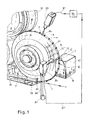
- Fig. 1 schematically shows a three-dimensional representation of an object inserter according to the invention.
- capsules for example capsules 9 filled with liquid
- the capsules 9 are applied by an accelerator wheel 10 to a capsule insert 71 in the form of a loading wheel.
- the capsules 9 are received in corresponding receptacles or object receptacles 72 and are held there, for example with suction.
- the capsules inserted into the receptacles are brought into the receiving region 84 or detection region 84 of the detection device 83. There it is detected whether a capsule 9 is present in a receptacle 72. In the event that this is not the case, a control signal is passed via the line 87 to a control device 86.
- the control device 86 controls accordingly via a line 87 'a discharge device 85 in the form of a compressed air relay or a valve.
- compressed air which is provided by a pump 89 via a pressure line 88, introduced into the Einlegead 71, there through openings 91 of the Einlegerads and a corresponding bore 90 in the region of the receptacle in which the Object or in this case the capsule 9 is held.
- the capsule 9 is then conveyed away or conveyed away into the collecting container 82.
- This process happens for a predeterminable number of adjacent capsules 9 in adjacent receptacles 72.
- capsules have already been conveyed away from the adjacent receptacles A, B and C. This has happened because in the recording 72 'no capsule 9 was inserted.
- the detection device 83 which is designed in this case as a light barrier.
- a light source is provided in the insert wheel 9, whose light is detected by the light barrier 83 in the event that no object 9 is inserted in a corresponding receptacle 72 or 72 '.
- the section of the filter strand 1 into which no capsules 9 have been correspondingly inserted is, after the strand has been cut to length by, for example, a knife device, discharged and then no longer serves to be further processed.
- the strand is a filter strand 1 which, for example, consists of cellulose acetate tattow and is initially introduced into an inlet funnel 80 in a somewhat fanned-out form.
- the inlet funnel 80 is designed slotted, so that the insert wheel 71 can penetrate into the inlet funnel 80 to insert in the insertion zone 78 according to capsules 9 in the filter strand 1.
- the filter strand 1, which is then at least partially filled with capsules, is then placed in a format from which in Fig.
- the sub-format 81 is shown schematically.
- a wrapping material strip such as a filter paper or a cigarette paper is then usually wound around the strand and glued, to then be cut into filter sections of multiple use length, for example to be cut off. This results then filter strand sections multiple use length, which are either completely filled with capsules or have no capsules.
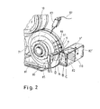
- Fig. 2 is a schematic representation of another object according to the invention 71, which is also shown in this embodiment as Einlegerad 71 shown.
- defective objects 9 ' can be sorted out.
- a defective object was inserted in the receptacle with the reference number B. Since this defective object would be inserted together with the objects arranged in the positions A, C and D in a same filter strand section or strand section, they are to be sorted out.
- the non-defective objects 9 have already been removed from the positions A and C and discharged into the collecting container 82.
- the defective object 9 'in position B was discharged into the collecting container 82'.
- the non-defective object 9 in position D is then discharged into the collecting container 82.
- This is done with different amounts of compressed air surges, which can be generated by the discharge device 85.
- the compressed air usually present in a production hall serves to supply the discharge device 85 designed as a valve.
- a throttle valve can be opened.
- the discharge device 85 can thus have a 3-way valve, in which a throttle in a second passage position no throttle and in a third position no passage is provided in a first passage position.
- the two collecting containers 82 and 82 ' are separated from one another by a half-height dividing wall 110, so that the objects 9' charged with a larger amount of compressed air can pass into the rear collecting container 82 '. Due to the larger compressed air flow and, for example, in that, for example, capsules that are not completely filled with liquid are lighter than capsules that are completely filled with liquid, correspondingly different trajectories result from the different blasts of compressed air.
- the detection device 83 can be a camera which records a contrast image or the contour of the object. In the event that a contour of the object is recorded, this contour is compared with a predeterminable contour. In the case of the recording of a contrast image, it can be provided that a plurality of variations of the contrast or even a contrast difference, which lies above a predefinable limit, leads to an ejection of the object within the object.
- Fig. 3 shows a schematic sectional view of another object inserter according to the invention in the form of a transfer device 30, which has an insert belt 31.
- This insert band 31 or its function is for example in the DE 10 2011 085 534.3 described in more detail, wherein according to the invention, a corresponding variation has been made.
- the separating and inserting device 20 has a separating device 21 and a transfer device 30.
- the separating device 21 has an object storage volume 22 with the width of an object position. It is thus a so-called “single-layer” device. This means that the objects are arranged in a single layer because the object supply volume 22 is limited in width to its diameter.
- the object supply volume 22 is in contact with a portion of the circumference of an accelerator wheel 10 with a circumferential annular groove 11 which rotates in the direction of arrow or direction of rotation 19 and thereby receives objects 9, 9 'from the object supply volume 22 and accelerates in the direction of rotation 19.
- the object supply volume 22 is delimited by the housing 25 of the separating device 21.
- the objects are stripped off the top edge of the wiper wedge 24 from the accelerator wheel 10 and deflected at the curved side surface of a bulge 23, so that they in turn are returned in the direction of the object supply volume 22.
- a large part of the objects remain in the object supply volume 22, whereby through an upper inlet 26 further objects can be refilled into the object supply volume 22.
- the housing 25 Downstream in the direction of rotation 19 of the accelerator 10, the housing 25 seals the annular groove 11 of the accelerator 10 to the outside.
- the object chain in the annular groove 11 of the accelerator wheel is therefore guided further with the accelerator wheel 10 through a transfer path 36a to a receiving path 36.
- the transfer route 36a the objects are still in the annular groove 11 of the accelerator 10.
- the transition from the transfer line 36a to the receiving path 36 of the transfer device is another, not shown in detail Abstreifkeil that ensures that the objects of the object chain from the annular groove 11 of Accelerator 10 are recorded in the receiving path 36.
- the receiving section 36 is a part of the transfer device 30, which in Fig. 3 is designed as an insert band 31.
- the insert belt 31, which has one or more rows of object receptacles 32 is moved in a conveying direction 31 a and thus moves parallel to the objects of the object chain in the recording path, but possibly with a certain differential speed, which in the course of parallel guidance in the Can also change recording path 36 by friction.
- two or more rows of object receptacles 32 may be provided.
- the upstream arranged organs are then preferably also designed such that the two or more rows of object receptacles 32 can be filled with objects.
- a negative pressure zone or a negative pressure region 35 is arranged on the inner side of the insertion band 31, in which the object holders 32 are acted upon from the inside with suction, so that objects that have entered the object receptacles 32 are held therein.
- the negative pressure region 35 extends over the entire length of the receiving path 36 as far as the insertion zone 38, in which the objects from the object holders 32 are inserted into a material strand 1.
- the further promoted Material strand with inserted objects then has the reference numeral 2.
- the conveying direction of the material strand 1, 2 is indicated by arrows.
- the insert belt 31 is guided over an upper deflection roller 33 and a lower deflection roller 34, whose directions of rotation are also shown.
- the lower deflection roller 34 is simultaneously formed for inserting the objects from the object receptacles 32 of the insertion band 31 into the material strand 1.
- a detection device 83 is provided which detects whether 32 images are recorded in the recordings or not or whether defective objects are recorded there. It can then be analogous to the procedure from the Fig. 1 and 2 objects ejected adjacent images or conveyed away, if one or more objects in adjacent recordings are missing or defective. Accordingly, those objects are conveyed away and not inserted into the strand 1 in the insertion zone 38, which would be brought into a strand section, which would have been assigned to the filter rod 3, for example.
- the conveying away or conveying away the wegzu overviewnden and not be introduced into the strand objects in this case also takes place with a discharge device 85.
- the conveyed objects are collected in a collecting container 82.
- the filter strand 1 is filled accordingly with objects and the filled filter strand 2 is then cut in the cutting device 4 in strand sections which correspond in this embodiment, a filter rod 3 or filled filter rod 3 '.
- the filter rod 3 is not filled with objects.
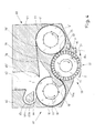
- Fig. 4 1 schematically shows another object inlay in the form of a loading pad 71 according to the invention.
- the loading pad 71 is part of a transfer device 70 which functions as follows:
- Fig. 4 shows first a separating and inserting device 60, which has a separating device 61 with an accelerator 10 in the upper and left part, wherein in a housing 65, an object supply volume 62 with a Abstreifkeil 64, a bulge 63 with island-shaped blocking surface 63a and curved channel 63b is formed in which objects in the annular groove 11 of the accelerator wheel are accelerated and transferred via a transfer path 76a to a receiving path 76 on a transfer device, which is designed as a loading wheel 71.
- the insert wheel 71 with the discrete object receptacles 72 rotates in the direction of the arrow.
- An object chain is transferred from the annular groove 11 of the accelerator wheel 10 into the receiving section 76 in the form of a channel, where it is guided past the object receivers 72 of the loading pad 71, wherein objects received in the object receptacles 72 are inserted into a material strand 1 in an insertion zone 78.
- Adjoining the receiving path 76 at the loading wheel 71 is a stripping wedge 75, which deflects the excess objects to a second accelerator wheel 10 ", these objects being received in the annular groove 11 of the second accelerator wheel 10 'and accelerated again in the direction of the arrow Housing 65 around the second accelerator 10 "around a return path 77 from or the return path 77 is formed as a portion of the annular groove 11 of the second accelerator wheel 10" again accelerated objects are removed by a second stripping wedge 75 'from the annular groove 11 of the second accelerator wheel 10 "and passed through a return channel 79 back into the pvorratsvolumen 62 where they can re-enter the annular groove 11 of the first accelerator 10.
- a detection device 83 which detects whether objects corresponding to the receptacles 72 are held and held there. In addition, it can also be detected here whether the held objects 9, 9 'in the recordings are defective or not.
- the distance between the detection device 83 and the removal device 85 is to be selected such that the predeterminable number of objects 9, 9 'can be removed or removed from adjacent receptacles 72, that is to say optionally also from leading adjacent receptacles 72.
- the collecting container 82 may be formed in two parts, so that non-defective objects 9 and defective objects 9 'are transferred into different parts of the collecting container 82 by setting differently strong pressure surges, of which the part for the non-defective objects 9 is connected to a conveying device, not shown that conveys the ejected non-defective objects 9 back to the object storage volume 62.
- the quality of the objects is checked. This may be, for example, whether a capsule filled with liquid is completely filled with liquid or not.
- the quality can also represent a density of an object, for example the density of an extrudate.
- the quality may also include the geometric shape or the size of the object to be inserted. Instead of ejecting the respective objects with compressed air, other removal measures can be taken. For example, mechanical guide devices may be provided.
- adjacent objects instead of four adjacent objects, a different number of adjacent objects arranged in adjacent receptacles can also be excluded from the further process. For example, two, three, four or more neighboring objects may be affected. The number of affected objects that are adjacent and carried away depends on how many objects would get into a strand section upon proper filling of the strand section. In the context of the invention, adjacent objects are understood to mean a number of objects arranged in the conveying direction in recordings.
- the removal device or the invention can serve to survive an unsafe phase without object shot.
- the detection device can indicate, for example, how many defects are still present, which also provides a measure of how far the process is already stabilized.
- the object feed without speed reduction can be switched off exactly when marked strand sections, which are known to the controller in time, can not be used for further production. This is, for example, a paper splice, that is to say a glued paper section when changing the wrapping material bob, or a tow change point.
- a filter rod or cigarette rod not filled with objects can deliberately be generated by the method according to the invention in order to check downstream sensors during production by, for example, cyclic plausibility tests.
Landscapes
- Cigarettes, Filters, And Manufacturing Of Filters (AREA)
- Manufacturing Of Cigar And Cigarette Tobacco (AREA)
- Specific Conveyance Elements (AREA)
Applications Claiming Priority (1)
| Application Number | Priority Date | Filing Date | Title |
|---|---|---|---|
| DE102012202763A DE102012202763A1 (de) | 2012-02-23 | 2012-02-23 | Objekteinleger und Verfahren zum Betrieb eines Objekteinlegers der Tabak verarbeitenden Industrie |
Publications (2)
| Publication Number | Publication Date |
|---|---|
| EP2630876A2 true EP2630876A2 (fr) | 2013-08-28 |
| EP2630876A3 EP2630876A3 (fr) | 2015-01-21 |
Family
ID=47722106
Family Applications (1)
| Application Number | Title | Priority Date | Filing Date |
|---|---|---|---|
| EP13155376.0A Withdrawn EP2630876A3 (fr) | 2012-02-23 | 2013-02-15 | Insert d'objet et procédé de fonctionnement d'un insert d'objet de l'industrie de traitement du tabac |
Country Status (4)
| Country | Link |
|---|---|
| EP (1) | EP2630876A3 (fr) |
| JP (1) | JP2013172713A (fr) |
| CN (1) | CN103284325A (fr) |
| DE (1) | DE102012202763A1 (fr) |
Cited By (1)
| Publication number | Priority date | Publication date | Assignee | Title |
|---|---|---|---|---|
| CN105170484A (zh) * | 2015-09-18 | 2015-12-23 | 盛浩洋 | 胶囊分拣机 |
Families Citing this family (4)
| Publication number | Priority date | Publication date | Assignee | Title |
|---|---|---|---|---|
| BR112018000867B1 (pt) * | 2015-08-24 | 2021-11-30 | Philip Morris Products S.A. | Método para fabricação de artigos formadores de aerossol com multicomponentes |
| CN107199181B (zh) * | 2017-05-25 | 2019-01-29 | 东莞市奇思电子科技有限公司 | 一种单级电子烟头分料机 |
| CN110604337B (zh) * | 2019-10-17 | 2021-07-13 | 浙江中烟工业有限责任公司 | 一种卷烟爆珠的检测装置及检测方法 |
| CN112869229B (zh) * | 2021-02-05 | 2022-04-19 | 河南中烟工业有限责任公司 | 具有滤棒实时在线检测剔除功能的双倍长烟支汇合装置 |
Citations (2)
| Publication number | Priority date | Publication date | Assignee | Title |
|---|---|---|---|---|
| WO2011083405A1 (fr) | 2010-01-05 | 2011-07-14 | Aiger Group Ag | Appareil et procédé d'insertion de capsules dans mèches de filtre |
| DE102011082309A1 (de) | 2011-09-07 | 2013-03-07 | Hauni Maschinenbau Ag | Sortieren von Flüssigkeitskapseln durch Füllstandsprüfung für das Einbringen in Stränge der Tabak verarbeitenden Industrie |
Family Cites Families (10)
| Publication number | Priority date | Publication date | Assignee | Title |
|---|---|---|---|---|
| DE10160822A1 (de) * | 2001-12-11 | 2003-06-18 | Hauni Maschinenbau Ag | Antrieb für Schneidvorrichtung |
| DE102005007214A1 (de) * | 2005-02-16 | 2006-08-24 | Hauni Maschinenbau Ag | Aufbereitung eines Streifens aus Filtermaterial der Tabak verarbeitenden Industrie |
| US7479098B2 (en) * | 2005-09-23 | 2009-01-20 | R. J. Reynolds Tobacco Company | Equipment for insertion of objects into smoking articles |
| DE102006027597A1 (de) * | 2006-06-13 | 2007-12-27 | Hauni Maschinenbau Aktiengesellschaft | Verfahren zum Betrieb einer Strangmaschine und Strangmaschine |
| DE102008010659B3 (de) * | 2008-02-22 | 2009-07-30 | Hauni Maschinenbau Ag | Filterstrangherstellung |
| DE102008019434B4 (de) * | 2008-04-17 | 2013-08-22 | Hauni Maschinenbau Ag | Beleimung von Materialstreifen der Tabak verarbeitenden Industrie |
| IT1408375B1 (it) * | 2010-10-20 | 2014-06-20 | Gd Spa | Unita' e metodo di alimentazione di elementi additivi a del materiale fibroso in una macchina per la produzione di articoli da fumo |
| DE102011017615A1 (de) | 2011-04-27 | 2012-10-31 | Hauni Maschinenbau Ag | Verfahren und Vorrichtung zum Einlegen von Objekten in einen Materialstrang der Tabak verarbeitenden Industrie |
| JP2014178117A (ja) * | 2011-07-06 | 2014-09-25 | Japan Tobacco Inc | カプセル検査装置及びその検査方法 |
| DE102011085534B4 (de) | 2011-11-01 | 2013-07-04 | Hauni Maschinenbau Ag | Verfahren und Vorrichtung zum Vereinzeln und Einlegen von Objekten in einen Materialstrang der Tabak verarbeitenden Industrie |
-
2012
- 2012-02-23 DE DE102012202763A patent/DE102012202763A1/de not_active Ceased
-
2013
- 2013-02-15 EP EP13155376.0A patent/EP2630876A3/fr not_active Withdrawn
- 2013-02-21 JP JP2013032015A patent/JP2013172713A/ja active Pending
- 2013-02-22 CN CN2013100564847A patent/CN103284325A/zh active Pending
Patent Citations (2)
| Publication number | Priority date | Publication date | Assignee | Title |
|---|---|---|---|---|
| WO2011083405A1 (fr) | 2010-01-05 | 2011-07-14 | Aiger Group Ag | Appareil et procédé d'insertion de capsules dans mèches de filtre |
| DE102011082309A1 (de) | 2011-09-07 | 2013-03-07 | Hauni Maschinenbau Ag | Sortieren von Flüssigkeitskapseln durch Füllstandsprüfung für das Einbringen in Stränge der Tabak verarbeitenden Industrie |
Cited By (1)
| Publication number | Priority date | Publication date | Assignee | Title |
|---|---|---|---|---|
| CN105170484A (zh) * | 2015-09-18 | 2015-12-23 | 盛浩洋 | 胶囊分拣机 |
Also Published As
| Publication number | Publication date |
|---|---|
| CN103284325A (zh) | 2013-09-11 |
| DE102012202763A1 (de) | 2013-08-29 |
| EP2630876A3 (fr) | 2015-01-21 |
| JP2013172713A (ja) | 2013-09-05 |
Similar Documents
| Publication | Publication Date | Title |
|---|---|---|
| EP2730183B1 (fr) | Dispositif et procédé de récupération de tabac provenant d'articles à fumer | |
| EP2243384A1 (fr) | Procédé et dispositif de contrôle de la qualité de tiges de filtres pourvues de capsules | |
| DE102015113820A1 (de) | Schiebetrommel der Tabak verarbeitenden Industrie | |
| DE102010043474A1 (de) | Verfahren und Vorrichtung zum Einlegen von Objekten in einen Filterstrang der Tabak verarbeitenden Industrie | |
| DE60219083T2 (de) | Verfahren und vorrichtung zum füllen von mehrfach-zigarettenfiltern mit hoher geschwindigkeit | |
| DE102009041318A1 (de) | Einlegen von Filtersegmenten in Filterstränge | |
| EP2363029A1 (fr) | Tambour de transport de l'industrie de traitement du tabac | |
| EP2477513A1 (fr) | Machine et procédé de production de filtres multisegments destinés à l'inductrie du tabac | |
| EP1364588A1 (fr) | Dispositif et procédé pour la formation d'au moins deux tiges de tabac dans une machine de fabrication de tige de tabac | |
| DE102012202763A1 (de) | Objekteinleger und Verfahren zum Betrieb eines Objekteinlegers der Tabak verarbeitenden Industrie | |
| EP2730182A2 (fr) | Dispositif et procédé de récupération de parties d'articles à fumer provenant d'articles à fumer | |
| EP2570038A1 (fr) | Dispositif d'alimentation de tiges de filtre | |
| EP2517583A2 (fr) | Procédé et dispositif d'insertion d'objets dans un tronçon de matière dans l'industrie de traitement du tabac | |
| DE102011085534B4 (de) | Verfahren und Vorrichtung zum Vereinzeln und Einlegen von Objekten in einen Materialstrang der Tabak verarbeitenden Industrie | |
| DE102011017581A1 (de) | Saugring für eine Fördertrommel der Tabak verarbeitenden Industrie | |
| EP2709472B1 (fr) | Bride de commande d'un tambour de transport pour l'industrie de la transformation du tabac | |
| DE102009040092A1 (de) | Verfahren und Vorrichtung zur Herstellung eines Filterstrangs | |
| EP3563696A2 (fr) | Tambour de collecte pour une machine de l'industrie de traitement du tabac | |
| EP1197155A2 (fr) | Procédé et dispositif de formation d'une tige de tabac | |
| EP1827143B1 (fr) | Tambour poussoir | |
| DE102006027597A1 (de) | Verfahren zum Betrieb einer Strangmaschine und Strangmaschine | |
| DE2433644A1 (de) | Verfahren und vorrichtung zur zigarettenherstellung | |
| DE102022125966A1 (de) | Verpackung von stabförmigen Produkten der Tabak verarbeitenden Industrie | |
| EP3735844B1 (fr) | Dispositif de transfert d'articles en forme de tige de l'industrie de traitement du tabac | |
| DE102010042766A1 (de) | Strangführungseinrichtung einer Maschine der Tabak verarbeitenden Industrie |
Legal Events
| Date | Code | Title | Description |
|---|---|---|---|
| PUAI | Public reference made under article 153(3) epc to a published international application that has entered the european phase |
Free format text: ORIGINAL CODE: 0009012 |
|
| AK | Designated contracting states |
Kind code of ref document: A2 Designated state(s): AL AT BE BG CH CY CZ DE DK EE ES FI FR GB GR HR HU IE IS IT LI LT LU LV MC MK MT NL NO PL PT RO RS SE SI SK SM TR |
|
| AX | Request for extension of the european patent |
Extension state: BA ME |
|
| PUAL | Search report despatched |
Free format text: ORIGINAL CODE: 0009013 |
|
| AK | Designated contracting states |
Kind code of ref document: A3 Designated state(s): AL AT BE BG CH CY CZ DE DK EE ES FI FR GB GR HR HU IE IS IT LI LT LU LV MC MK MT NL NO PL PT RO RS SE SI SK SM TR |
|
| AX | Request for extension of the european patent |
Extension state: BA ME |
|
| RIC1 | Information provided on ipc code assigned before grant |
Ipc: A24D 3/02 20060101AFI20141216BHEP Ipc: B07C 5/342 20060101ALI20141216BHEP |
|
| STAA | Information on the status of an ep patent application or granted ep patent |
Free format text: STATUS: THE APPLICATION IS DEEMED TO BE WITHDRAWN |
|
| 18D | Application deemed to be withdrawn |
Effective date: 20150722 |