EP1197155A2 - Procédé et dispositif de formation d'une tige de tabac - Google Patents
Procédé et dispositif de formation d'une tige de tabac Download PDFInfo
- Publication number
- EP1197155A2 EP1197155A2 EP01122991A EP01122991A EP1197155A2 EP 1197155 A2 EP1197155 A2 EP 1197155A2 EP 01122991 A EP01122991 A EP 01122991A EP 01122991 A EP01122991 A EP 01122991A EP 1197155 A2 EP1197155 A2 EP 1197155A2
- Authority
- EP
- European Patent Office
- Prior art keywords
- dust
- tobacco
- strand conveyor
- vacuum chamber
- strand
- Prior art date
- Legal status (The legal status is an assumption and is not a legal conclusion. Google has not performed a legal analysis and makes no representation as to the accuracy of the status listed.)
- Granted
Links
Images

Classifications
-
- A—HUMAN NECESSITIES
- A24—TOBACCO; CIGARS; CIGARETTES; SIMULATED SMOKING DEVICES; SMOKERS' REQUISITES
- A24C—MACHINES FOR MAKING CIGARS OR CIGARETTES
- A24C5/00—Making cigarettes; Making tipping materials for, or attaching filters or mouthpieces to, cigars or cigarettes
- A24C5/14—Machines of the continuous-rod type
- A24C5/18—Forming the rod
-
- A—HUMAN NECESSITIES
- A24—TOBACCO; CIGARS; CIGARETTES; SIMULATED SMOKING DEVICES; SMOKERS' REQUISITES
- A24C—MACHINES FOR MAKING CIGARS OR CIGARETTES
- A24C5/00—Making cigarettes; Making tipping materials for, or attaching filters or mouthpieces to, cigars or cigarettes
- A24C5/14—Machines of the continuous-rod type
- A24C5/18—Forming the rod
- A24C5/1835—Multiple rod making devices
Definitions
- the invention relates to a method for forming at least one strand of tobacco, in which tobacco fibers in a wide shower at least one air permeable Strand conveyors are fed and on this conveyor by means of suction air are held, further contained in this air sucked by the strand conveyor Dust is largely completely separated from the air and this separated dust is partially added to the tobacco rod.
- the invention further relates to a device for forming at least one tobacco rod with a distribution device for forming a wide shower Tobacco fibers, at least one air-permeable, endless circulating strand conveyor for removing the at least one tobacco rod formed from the shower, Feeding means for feeding the shower to the at least one Strand conveyor, a first vacuum chamber for applying a vacuum to a first section of the side of the at least facing away from the tobacco rod a strand conveyor, first suction means for suctioning through the air entering at least one strand conveyor into the first vacuum chamber, a separator for separating the air contained in this extracted Dust and means of transport with at least one discharge opening for transport of the separated dust to the at least one strand conveyor.
- tobacco processing machines includes machines for manufacturing understanding of cigarettes, but also machines for producing tobacco cartridges, Cigarillos or cigars, insofar as they follow the procedure mentioned Use strand formation.
- tobacco is made from a distribution device Taken stock and a shower of largely isolated tobacco fibers spread.
- This tobacco shower is usually accelerated by transport air and distracted and finally on or under a revolving air permeable Strand conveyor heaped into an endless tobacco rod.
- This Strand is held on the strand conveyor by negative pressure, which by means of a first vacuum chamber on the side of the strand conveyor facing away from the strand is created.
- the air passing through the tobacco rod and the line conveyor is extracted by suction from the first vacuum chamber.
- About density To keep the tobacco rod as constant as possible, the tobacco is left with a surplus which is later trimmed by a leveler.
- a corresponding distribution device is z. B. described in DE 39 19 720 A1 of the applicant.
- the task arises to develop a method in which the rough Dust particles are added to the tobacco rod and at the same time there is a risk of There is no accumulation of fine dust.
- the task is to develop a device which enables this method to be carried out.
- the object is achieved according to the invention solved that the largely all dust in a coarse and a fine fraction is divided, the coarse fraction being added to the tobacco rod while the fine fraction is fed to a central dedusting unit.
- This also expressly includes procedures in which a certain Part of the separated dust temporarily or continuously before fractionation for measuring or other purposes. Such procedures are also intended included in which, in addition to the exhaust air mentioned, exhaust air cleaned from other sub-processes of tobacco processing in dust separation as far as this additional exhaust air is also recyclable coarse tobacco parts contains.
- Such a method can be designed particularly simply in that the Dust is fed back to the strand conveyor together with the tobacco shower and the division of the dust into the coarse and fine fractions by sieving of the strand conveyor and possibly already on this tobacco heaped up.
- the separated dust is transported back to the strand conveyor preferably pneumatic.
- each tobacco rod to be produced is preferably a partial stream of Dust supplied.
- the division is preferably made before or during the Transportes to the strand conveyors.
- the sieving action can be used particularly advantageously when the addition the dust takes place on a width which is smaller than the width of the tobacco shower, the one passing through the strand conveyor in the area of dust addition Air and the fine dust contained in it are extracted separately and one Central dedusting is supplied.
- the width of the tobacco shower To understand expansion in the conveying direction of the strand conveyor.
- a particularly reliable function of the method is achieved in that the The amount of separately extracted air is controlled.
- the control is preferably carried out through a control loop, which advantageously ensures that the Vacuum runs steadily along the strand conveyor.
- this at least one second vacuum chamber for applying a vacuum to a second section of the Associated side of the at least one strand conveyor facing away from the tobacco rod is to which second suction means are connected in order to achieve the minimum through the a strand conveyor entering the at least one second vacuum chamber To suck out air.
- the feed means for the tobacco shower special means for dividing the shower into several partial showers from which a tobacco rod is piled up on several strand conveyors and include the means of transport for the separated dust also means for dividing the dust into several partial streams, which through several discharge openings can be fed to the individual strand conveyors. Further is every single strand conveyor in the area of the corresponding discharge opening a second vacuum chamber is assigned to the means of transport. In this Case, it is further advantageous if the device for dividing the dust Contains adjusting means by which the quantitative relationships of the individual partial flows of the dust can be controlled.
- the means of transport for the separated dust are preferably pneumatic Delivery lines executed.
- the extension is the second Vacuum chamber in the conveying direction of the strand conveyor much smaller than that the first vacuum chamber.
- the second vacuum chamber upstream of the first vacuum chamber in the conveying direction of the strand conveyor or integrated into this.
- the second vacuum chamber in the conveying direction of the strand conveyor larger than the delivery opening of the means of transport.
- a Further optimization is achieved in that the second vacuum chamber against the discharge opening of the transport means in the conveying direction of the strand conveyor is offset.
- the device becomes structurally particularly simple if in a further embodiment the transport means with their discharge opening in the feed means for the Open tobacco shower.
- the device runs particularly safely when it is in close proximity to the strand conveyor arranged discharge opening of the transport means with a component in the conveying direction of the at least one strand conveyor is aligned.
- adjusting means for the Control of the amount of air drawn off by the second suction means is provided.
- a control unit for controlling this amount of air is preferably provided.
- the device shown in Figure 1 consists of a distributor device 1, which Feed means 2 for guiding a tobacco shower 3 are arranged downstream.
- a such distribution device is such. B. described in DE 39 19 720 A1 of the applicant and component z. B. the cigarette production machine sold by the applicant PROTOS 2.
- In the feed means 2 are separating means 4 for dividing the tobacco shower 3 arranged in two partial showers 5, 6.
- the feed means 2 lead to two endless strand conveyors 7, 8, which around deflection rollers 9, 10, 11, 12 are guided and revolve in the direction of arrows 13, 14.
- the strand conveyors 7, 8 delimit a first vacuum chamber positioned opposite the feed means 2 15.
- each of the strand conveyors 7, 8 is a leveler 16, 17 assigned.
- a dust collector 19 can be used to the first suction means 20.
- Dust separator 19 can e.g. B. a Mahle industrial filter type SFK 1560 Knecht Filterwerke GmbH, ⁇ hringen.
- From the dust collector 19 leads a conveyor line 21 to separating means 22 for dividing a dust flow to two further pneumatic conveying lines 23, 24.
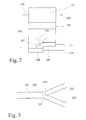
- the separating means 22 can as a divided collecting shaft with subsequent pneumatic conveying be configured, such a configuration is shown in Figure 2.
- the release agent However, 22 can also be used as a fork in a pneumatic delivery line be configured, in this case the delivery line 21 is also a pneumatic Delivery line, which is preceded by an ejector 25.
- the delivery line 21 is also a pneumatic Delivery line, which is preceded by an ejector 25.
- 24 are arranged discharge openings 26, 27.
- the discharge openings, represented by 26a, 27a, into the feed means 2 or the discharge openings, represented by 26b, 27b, are arranged upstream of the feed means 2 in the conveying direction of the strand conveyors 7, 8.
- the opening of the discharge openings 26a, 27a can preferably be arranged in close proximity to the strand conveyors 7, 8, or on one another location between the distribution device 1 and the strand conveyors 7, 8, if this is particularly easy to access in the construction of the machine in question is.
- Each of the discharge openings 26, 27 is on the opposite one Side of the strand conveyor 7, 8 assigned a second vacuum chamber 28, 29 which depending on the position of the discharge openings 26, 27 either, represented by 28a, 29a, are arranged within the first vacuum chamber 15, or are shown through 28b, 29b, the first vacuum chamber 15 in the conveying direction of the strand conveyors 7, 8 are arranged.
- second suction means 35 To the second vacuum chambers 28, 29 are over second exhaust air lines 30, 31, 32 and adjusting means 33, 34 second suction means 35 connected.
- adjusting means 33, 34 for. B. Throttle valves can be used.
- pressure sensors 36, 37, 38 Within the second vacuum chamber 28, 29 and within the first vacuum chamber 15, pressure sensors 36, 37, 38 are arranged, which with a Control unit 39 are connected, which in turn by control lines 40, 41, 42 is connected to the adjusting means 33, 34 and the second suction means 35.
- Tobacco to be processed becomes a wide one in the distribution device 1
- Spread tobacco shower 3 which is delivered into the feed means 2.
- the shower 3 is divided into two showers 5, 6.
- the equalizers 16, 17 excess portions 45, 46 of the Tobacco strands 43, 44 separated.
- air laden with dust 47 passes through the tobacco rods 43, 44 and the strand conveyors 7, 8 in the first vacuum chamber 15.
- This air is by means of the first suction means 20 through the first exhaust line 18 into the dust collector 19 promoted where the dust contained in it separated and into the Conveying line 21 is transferred.
- the dust is then in accordance the description of Figures 2 or 3 divided into two sub-streams, which be introduced into the pneumatic conveying lines 23, 24.
- dust 48, 49 passes through the corresponding discharge openings 26, 27 in the direction of the corresponding strand conveyors 7, 8. flow the discharge openings, represented by 26a, 27a in the feed means 2, the Dust together with the partial showers 5, 6 from tobacco on the strand conveyors 7, 8 heaped up.
- a coarse fraction 50, 51 is already created by the respective one partially retained tobacco rod 43, 44 and with this conveyed together.
- a fine fraction 52, 53 occurs due to the in the second negative pressure chambers 28a, 29a prevailing negative pressure by the corresponding tobacco rod 43, 44 and the corresponding strand conveyor 7, 8 through into the respective second vacuum chamber 28a, 29a. From there the fine Dust fraction 52, 53 by means of the second suction means 35 through the second exhaust air lines 30, 31, 32 suctioned off.
- the coarse dust fraction 50, 51 is retained by the unused strand conveyors 7, 8 while the fine fraction 52, 53 passes through it into the second Vacuum chambers 28b, 29b occurs.
- the negative pressure in the second negative pressure chambers 28, 29 and in the first vacuum chamber 15 is by pressure sensors 36, 37, 38 measured.
- the control unit 39 the throttle valves 33, 34 and / or the drive of the second suction means 35 controlled so that at the transitions between the first vacuum chamber 15 and the second vacuum chambers 28, 29 no pressure jumps occur.
- the mode of operation of the release agents shown in FIG. 2 is as follows: In one Dust contained in air flow supplied through line 102 is removed by a Dust separator 101 separated from the air and through a lock 104, which z. B. can be designed as a rotary valve, in a collecting container 105 transferred. The cleaned air is discharged through a line 103. The Dust falling from the lock 104 into the collecting container 105 is removed by a pivotable partition 106 divided into two sub-streams, each of which by means of one of two ejectors 108, 109 into one of two pneumatic ones assigned to them Delivery lines 110, 111 is abandoned. By swiveling the partition 106 by means of a lever 107, the quantitative ratio of the partial flows of the Dust can be adjusted. Instead of the manually operated lever 107 can also an automatic, e.g. B. electromotive setting.
- the mode of operation of the means shown in FIG. 3 is as follows: one in a feeding Pneumatic feed line 201 supplied dust stream is in one Branch area 203 through the pivotable end 205 of a partition 204 divided into two partial streams, which are discharged through the pneumatic conveying lines 202, 203 are transported away.
- the end 205 of the partition 204 can be the quantitative ratio of the partial flows can be set. As with the means shown in FIG. 2, this setting can be used manually using a lever, not shown, or automatically, e.g. B. electromotive, respectively.
Landscapes
- Manufacturing Of Cigar And Cigarette Tobacco (AREA)
- Manufacture Of Tobacco Products (AREA)
Applications Claiming Priority (2)
| Application Number | Priority Date | Filing Date | Title |
|---|---|---|---|
| DE10051031A DE10051031A1 (de) | 2000-10-14 | 2000-10-14 | Verfahren und Vorrichtung zum Bilden eines Tabakstranges |
| DE10051031 | 2000-10-14 |
Publications (3)
| Publication Number | Publication Date |
|---|---|
| EP1197155A2 true EP1197155A2 (fr) | 2002-04-17 |
| EP1197155A3 EP1197155A3 (fr) | 2005-06-15 |
| EP1197155B1 EP1197155B1 (fr) | 2006-07-26 |
Family
ID=7659831
Family Applications (1)
| Application Number | Title | Priority Date | Filing Date |
|---|---|---|---|
| EP01122991A Expired - Lifetime EP1197155B1 (fr) | 2000-10-14 | 2001-09-26 | Procédé et dispositif de formation d'une tige de tabac |
Country Status (8)
| Country | Link |
|---|---|
| US (2) | US6877515B2 (fr) |
| EP (1) | EP1197155B1 (fr) |
| JP (1) | JP2002125650A (fr) |
| CN (1) | CN1192727C (fr) |
| AT (1) | ATE333805T1 (fr) |
| DE (2) | DE10051031A1 (fr) |
| ES (1) | ES2266065T3 (fr) |
| PL (1) | PL203996B1 (fr) |
Cited By (4)
| Publication number | Priority date | Publication date | Assignee | Title |
|---|---|---|---|---|
| EP2238844A1 (fr) * | 2009-04-02 | 2010-10-13 | HAUNI Maschinenbau AG | Génération de dépression sur une machine de l'industrie de traitement du tabac |
| EP2462819A3 (fr) * | 2010-12-10 | 2014-12-10 | Riedel Filtertechnik GmbH | Agencement de réglage pour une machine de fabrication de cigarettes et procédé de réglage du transport de la matière de remplissage de cigarettes |
| EP3020288A1 (fr) * | 2014-11-14 | 2016-05-18 | HAUNI Maschinenbau AG | Procède et dispositif de formation d'une tige de tabac à partir de fibres de tabac transportées |
| CN105639720A (zh) * | 2016-03-24 | 2016-06-08 | 龙岩烟草工业有限责任公司 | 一种风力送丝系统的物料损失测量系统及方法 |
Families Citing this family (4)
| Publication number | Priority date | Publication date | Assignee | Title |
|---|---|---|---|---|
| CA2499853C (fr) * | 2004-03-15 | 2012-11-13 | Universal Leaf Tobacco Company, Inc. | Appareil et methode de balayage et de tri de feuilles de tabac |
| DE102005015781A1 (de) * | 2005-04-01 | 2006-10-05 | Hauni Maschinenbau Ag | Verfahren und Vorrichtung zum Trocknen eines faserförmigen Gutes |
| US8281931B2 (en) * | 2009-09-18 | 2012-10-09 | Key Technology, Inc. | Apparatus and method for post-threshing inspection and sorting of tobacco lamina |
| ES1078301Y (es) * | 2012-08-06 | 2013-03-20 | Univ Alicante | Dispositivo de incorporación de aditivos sólidos insolubles pulverulentos al tabaco |
Family Cites Families (9)
| Publication number | Priority date | Publication date | Assignee | Title |
|---|---|---|---|---|
| GB974972A (en) * | 1960-02-09 | 1964-11-11 | James Ernest Morris | Improvements in or relating to tobacco-manipulating apparatus |
| GB1103703A (en) * | 1964-09-15 | 1968-02-21 | Vokes Ltd | Improvements in dust collector systems for cigarette making machines |
| DE2506839C2 (de) * | 1975-02-18 | 1987-04-23 | Hauni-Werke Körber & Co KG, 2050 Hamburg | Vorrichtung zum Bilden eines Tabakfüllstromes |
| US4281670A (en) * | 1977-06-13 | 1981-08-04 | Hauni-Werke Korber & Co. Kg | Apparatus for increasing the permeability of wrapping material for rod-shaped smokers products |
| DE3544769C2 (de) * | 1985-12-18 | 1994-12-08 | Hauni Werke Koerber & Co Kg | Strangmaschine zum Herstellen von stabförmigen Artikeln der tabakverarbeitenden Industrie |
| DE3919720C2 (de) * | 1989-06-16 | 1998-02-19 | Hauni Werke Koerber & Co Kg | Verfahren und Vorrichtung zur gleichzeitigen Herstellung von zwei Endlos-Tabaksträngen |
| DE4407789A1 (de) * | 1994-03-09 | 1995-09-14 | Hauni Werke Koerber & Co Kg | Schwingförderrinne zum Transportieren von Schüttgut, insbesondere Tabak |
| DE4425040A1 (de) * | 1994-07-15 | 1996-02-08 | Tabac Fab Reunies Sa | Verfahren und Vorrichtung zum Entstauben und Kühlen der Abluft einer Zigarettenherstellungsanlage |
| DE19514925A1 (de) * | 1995-04-22 | 1996-10-24 | Hauni Maschinenbau Ag | Verfahren und Vorrichtung zum Aufbereiten von bei der Herstellung von Artikeln der tabakverarbeitenden Industrie anfallenden Abluft |
-
2000
- 2000-10-14 DE DE10051031A patent/DE10051031A1/de not_active Withdrawn
-
2001
- 2001-09-25 JP JP2001290984A patent/JP2002125650A/ja not_active Withdrawn
- 2001-09-26 AT AT01122991T patent/ATE333805T1/de not_active IP Right Cessation
- 2001-09-26 EP EP01122991A patent/EP1197155B1/fr not_active Expired - Lifetime
- 2001-09-26 DE DE50110533T patent/DE50110533D1/de not_active Expired - Lifetime
- 2001-09-26 ES ES01122991T patent/ES2266065T3/es not_active Expired - Lifetime
- 2001-10-11 PL PL350074A patent/PL203996B1/pl not_active IP Right Cessation
- 2001-10-12 CN CNB011411902A patent/CN1192727C/zh not_active Expired - Fee Related
- 2001-10-15 US US09/976,291 patent/US6877515B2/en not_active Expired - Fee Related
-
2003
- 2003-09-05 US US10/655,213 patent/US6814080B2/en not_active Expired - Fee Related
Cited By (4)
| Publication number | Priority date | Publication date | Assignee | Title |
|---|---|---|---|---|
| EP2238844A1 (fr) * | 2009-04-02 | 2010-10-13 | HAUNI Maschinenbau AG | Génération de dépression sur une machine de l'industrie de traitement du tabac |
| EP2462819A3 (fr) * | 2010-12-10 | 2014-12-10 | Riedel Filtertechnik GmbH | Agencement de réglage pour une machine de fabrication de cigarettes et procédé de réglage du transport de la matière de remplissage de cigarettes |
| EP3020288A1 (fr) * | 2014-11-14 | 2016-05-18 | HAUNI Maschinenbau AG | Procède et dispositif de formation d'une tige de tabac à partir de fibres de tabac transportées |
| CN105639720A (zh) * | 2016-03-24 | 2016-06-08 | 龙岩烟草工业有限责任公司 | 一种风力送丝系统的物料损失测量系统及方法 |
Also Published As
| Publication number | Publication date |
|---|---|
| EP1197155A3 (fr) | 2005-06-15 |
| PL350074A1 (en) | 2002-04-22 |
| US6877515B2 (en) | 2005-04-12 |
| DE10051031A1 (de) | 2002-04-18 |
| ES2266065T3 (es) | 2007-03-01 |
| DE50110533D1 (de) | 2006-09-07 |
| ATE333805T1 (de) | 2006-08-15 |
| US20020043268A1 (en) | 2002-04-18 |
| CN1192727C (zh) | 2005-03-16 |
| US6814080B2 (en) | 2004-11-09 |
| JP2002125650A (ja) | 2002-05-08 |
| EP1197155B1 (fr) | 2006-07-26 |
| US20040060570A1 (en) | 2004-04-01 |
| PL203996B1 (pl) | 2009-11-30 |
| CN1347669A (zh) | 2002-05-08 |
Similar Documents
| Publication | Publication Date | Title |
|---|---|---|
| EP1364588B1 (fr) | Dispositif et procédé pour la formation d'au moins deux tiges de tabac dans une machine de fabrication de tige de tabac | |
| EP2363029A1 (fr) | Tambour de transport de l'industrie de traitement du tabac | |
| DE60219083T2 (de) | Verfahren und vorrichtung zum füllen von mehrfach-zigarettenfiltern mit hoher geschwindigkeit | |
| DE1245820B (de) | Vorrichtung zum Bilden eines fortlaufenden Tabakstroms | |
| EP2505087B1 (fr) | Procédé et dispositif de fabrication de tiges dans l'industrie du traitement du tabac | |
| EP1197155B1 (fr) | Procédé et dispositif de formation d'une tige de tabac | |
| EP2026669B1 (fr) | Procédé pour faire fonctionner une machine de fabrication de boudins et machine de fabrication de boudins | |
| DE10035692A1 (de) | Verfahren und Vorrichtung zum Vereinzeln von Tabakfasern | |
| DE3345609A1 (de) | Verfahren und vorrichtung zum bilden von stabfoermigen artikeln der tabakverarbeitenden industrie | |
| DE3839431A1 (de) | Verfahren und vorrichtung zur rueckgewinnung von tabak aus fehlerhaften zigaretten | |
| EP1520488A1 (fr) | Dispositif d'élimination de corps étrangers d'un courant de tabac | |
| DE3744562A1 (de) | Tabakfoerdereinrichtung fuer zigarettenfertigungsmaschinen | |
| DE19508139A1 (de) | Einrichtung zum Abführen überschüssiger Prozeßluft aus einem Verteiler einer tabakverarbeitenden Maschine | |
| EP1275311A2 (fr) | Dispositif pour préparer un courant de fibres dans l'industrie du tabac | |
| EP1106086B1 (fr) | Procédé de transport d'articles en forme de tige et appareil pour transporter des récipients | |
| EP2517582A2 (fr) | Bague d'aspiration pour un tambour de transport dans l'industrie de traitement du tabac | |
| EP1250855A1 (fr) | Procédé et dispositif pour éliminer une perturbation dans un canal à tabac d'une machine de fabrication de tige de tabac | |
| DE3919720C2 (de) | Verfahren und Vorrichtung zur gleichzeitigen Herstellung von zwei Endlos-Tabaksträngen | |
| EP1405573B1 (fr) | Egalisateur pour machine de tige de cigarette | |
| EP2253230B1 (fr) | Courroie porteuse d'aspiration et procédé de fabrication d'une tige de l'industrie de traitement du tabac | |
| DE3232792A1 (de) | Foerdervorrichtung fuer stabfoermige artikel der tabakverarbeitenden industrie | |
| EP3923747B1 (fr) | Récipient collecteur pour des feuilles de liaison | |
| EP2481304B1 (fr) | Alimentation de produits en forme de tiges de l'industrie de traitement du tabac dans un récipient de stockage | |
| EP1529449A1 (fr) | Appareil pour séparer tabac et air, et dispositif et procédé pour la formation d'au moins deux tiges de tabac dans une machine de fabrication de tige de tabac | |
| EP3266319A1 (fr) | Procédé et dispositif de séparation de résidus provenant de la fabrication de cigarettes |
Legal Events
| Date | Code | Title | Description |
|---|---|---|---|
| PUAI | Public reference made under article 153(3) epc to a published international application that has entered the european phase |
Free format text: ORIGINAL CODE: 0009012 |
|
| AK | Designated contracting states |
Kind code of ref document: A2 Designated state(s): AT BE CH CY DE DK ES FI FR GB GR IE IT LI LU MC NL PT SE TR |
|
| AX | Request for extension of the european patent |
Free format text: AL;LT;LV;MK;RO;SI |
|
| PUAL | Search report despatched |
Free format text: ORIGINAL CODE: 0009013 |
|
| AK | Designated contracting states |
Kind code of ref document: A3 Designated state(s): AT BE CH CY DE DK ES FI FR GB GR IE IT LI LU MC NL PT SE TR |
|
| AX | Request for extension of the european patent |
Extension state: AL LT LV MK RO SI |
|
| 17P | Request for examination filed |
Effective date: 20051011 |
|
| AKX | Designation fees paid |
Designated state(s): AT BE CH CY DE DK ES FI FR GB GR IE IT LI LU MC NL PT SE TR |
|
| GRAP | Despatch of communication of intention to grant a patent |
Free format text: ORIGINAL CODE: EPIDOSNIGR1 |
|
| GRAS | Grant fee paid |
Free format text: ORIGINAL CODE: EPIDOSNIGR3 |
|
| GRAA | (expected) grant |
Free format text: ORIGINAL CODE: 0009210 |
|
| AK | Designated contracting states |
Kind code of ref document: B1 Designated state(s): AT BE CH CY DE DK ES FI FR GB GR IE IT LI LU MC NL PT SE TR |
|
| PG25 | Lapsed in a contracting state [announced via postgrant information from national office to epo] |
Ref country code: IE Free format text: LAPSE BECAUSE OF FAILURE TO SUBMIT A TRANSLATION OF THE DESCRIPTION OR TO PAY THE FEE WITHIN THE PRESCRIBED TIME-LIMIT Effective date: 20060726 Ref country code: FI Free format text: LAPSE BECAUSE OF FAILURE TO SUBMIT A TRANSLATION OF THE DESCRIPTION OR TO PAY THE FEE WITHIN THE PRESCRIBED TIME-LIMIT Effective date: 20060726 |
|
| REG | Reference to a national code |
Ref country code: GB Ref legal event code: FG4D Free format text: NOT ENGLISH |
|
| REG | Reference to a national code |
Ref country code: CH Ref legal event code: EP |
|
| GBT | Gb: translation of ep patent filed (gb section 77(6)(a)/1977) |
Effective date: 20060726 |
|
| REG | Reference to a national code |
Ref country code: IE Ref legal event code: FG4D Free format text: LANGUAGE OF EP DOCUMENT: GERMAN |
|
| REF | Corresponds to: |
Ref document number: 50110533 Country of ref document: DE Date of ref document: 20060907 Kind code of ref document: P |
|
| PG25 | Lapsed in a contracting state [announced via postgrant information from national office to epo] |
Ref country code: BE Free format text: LAPSE BECAUSE OF NON-PAYMENT OF DUE FEES Effective date: 20060930 Ref country code: MC Free format text: LAPSE BECAUSE OF NON-PAYMENT OF DUE FEES Effective date: 20060930 |
|
| PG25 | Lapsed in a contracting state [announced via postgrant information from national office to epo] |
Ref country code: DK Free format text: LAPSE BECAUSE OF FAILURE TO SUBMIT A TRANSLATION OF THE DESCRIPTION OR TO PAY THE FEE WITHIN THE PRESCRIBED TIME-LIMIT Effective date: 20061026 Ref country code: SE Free format text: LAPSE BECAUSE OF FAILURE TO SUBMIT A TRANSLATION OF THE DESCRIPTION OR TO PAY THE FEE WITHIN THE PRESCRIBED TIME-LIMIT Effective date: 20061026 |
|
| PG25 | Lapsed in a contracting state [announced via postgrant information from national office to epo] |
Ref country code: PT Free format text: LAPSE BECAUSE OF FAILURE TO SUBMIT A TRANSLATION OF THE DESCRIPTION OR TO PAY THE FEE WITHIN THE PRESCRIBED TIME-LIMIT Effective date: 20061226 |
|
| REG | Reference to a national code |
Ref country code: IE Ref legal event code: FD4D |
|
| ET | Fr: translation filed | ||
| REG | Reference to a national code |
Ref country code: ES Ref legal event code: FG2A Ref document number: 2266065 Country of ref document: ES Kind code of ref document: T3 |
|
| PLBE | No opposition filed within time limit |
Free format text: ORIGINAL CODE: 0009261 |
|
| STAA | Information on the status of an ep patent application or granted ep patent |
Free format text: STATUS: NO OPPOSITION FILED WITHIN TIME LIMIT |
|
| 26N | No opposition filed |
Effective date: 20070427 |
|
| PGFP | Annual fee paid to national office [announced via postgrant information from national office to epo] |
Ref country code: ES Payment date: 20070926 Year of fee payment: 7 |
|
| PG25 | Lapsed in a contracting state [announced via postgrant information from national office to epo] |
Ref country code: AT Free format text: LAPSE BECAUSE OF NON-PAYMENT OF DUE FEES Effective date: 20060926 |
|
| BERE | Be: lapsed |
Owner name: HAUNI MASCHINENBAU A.G. Effective date: 20060930 |
|
| PG25 | Lapsed in a contracting state [announced via postgrant information from national office to epo] |
Ref country code: GR Free format text: LAPSE BECAUSE OF FAILURE TO SUBMIT A TRANSLATION OF THE DESCRIPTION OR TO PAY THE FEE WITHIN THE PRESCRIBED TIME-LIMIT Effective date: 20061027 |
|
| PGFP | Annual fee paid to national office [announced via postgrant information from national office to epo] |
Ref country code: FR Payment date: 20070914 Year of fee payment: 7 |
|
| PG25 | Lapsed in a contracting state [announced via postgrant information from national office to epo] |
Ref country code: LU Free format text: LAPSE BECAUSE OF NON-PAYMENT OF DUE FEES Effective date: 20060926 Ref country code: TR Free format text: LAPSE BECAUSE OF FAILURE TO SUBMIT A TRANSLATION OF THE DESCRIPTION OR TO PAY THE FEE WITHIN THE PRESCRIBED TIME-LIMIT Effective date: 20060726 |
|
| PG25 | Lapsed in a contracting state [announced via postgrant information from national office to epo] |
Ref country code: CY Free format text: LAPSE BECAUSE OF FAILURE TO SUBMIT A TRANSLATION OF THE DESCRIPTION OR TO PAY THE FEE WITHIN THE PRESCRIBED TIME-LIMIT Effective date: 20060726 |
|
| REG | Reference to a national code |
Ref country code: FR Ref legal event code: ST Effective date: 20090529 |
|
| PG25 | Lapsed in a contracting state [announced via postgrant information from national office to epo] |
Ref country code: FR Free format text: LAPSE BECAUSE OF NON-PAYMENT OF DUE FEES Effective date: 20080930 |
|
| REG | Reference to a national code |
Ref country code: ES Ref legal event code: FD2A Effective date: 20080927 |
|
| PG25 | Lapsed in a contracting state [announced via postgrant information from national office to epo] |
Ref country code: ES Free format text: LAPSE BECAUSE OF NON-PAYMENT OF DUE FEES Effective date: 20080927 |
|
| PGFP | Annual fee paid to national office [announced via postgrant information from national office to epo] |
Ref country code: GB Payment date: 20100929 Year of fee payment: 10 |
|
| PGFP | Annual fee paid to national office [announced via postgrant information from national office to epo] |
Ref country code: NL Payment date: 20100929 Year of fee payment: 10 |
|
| PGFP | Annual fee paid to national office [announced via postgrant information from national office to epo] |
Ref country code: CH Payment date: 20101015 Year of fee payment: 10 |
|
| REG | Reference to a national code |
Ref country code: NL Ref legal event code: V1 Effective date: 20120401 |
|
| REG | Reference to a national code |
Ref country code: CH Ref legal event code: PL |
|
| GBPC | Gb: european patent ceased through non-payment of renewal fee |
Effective date: 20110926 |
|
| PG25 | Lapsed in a contracting state [announced via postgrant information from national office to epo] |
Ref country code: NL Free format text: LAPSE BECAUSE OF NON-PAYMENT OF DUE FEES Effective date: 20120401 Ref country code: CH Free format text: LAPSE BECAUSE OF NON-PAYMENT OF DUE FEES Effective date: 20110930 Ref country code: LI Free format text: LAPSE BECAUSE OF NON-PAYMENT OF DUE FEES Effective date: 20110930 |
|
| PG25 | Lapsed in a contracting state [announced via postgrant information from national office to epo] |
Ref country code: GB Free format text: LAPSE BECAUSE OF NON-PAYMENT OF DUE FEES Effective date: 20110926 |
|
| REG | Reference to a national code |
Ref country code: DE Ref legal event code: R081 Ref document number: 50110533 Country of ref document: DE Owner name: HAUNI MASCHINENBAU GMBH, DE Free format text: FORMER OWNER: HAUNI MASCHINENBAU AG, 21033 HAMBURG, DE |
|
| PGFP | Annual fee paid to national office [announced via postgrant information from national office to epo] |
Ref country code: DE Payment date: 20160930 Year of fee payment: 16 |
|
| PGFP | Annual fee paid to national office [announced via postgrant information from national office to epo] |
Ref country code: IT Payment date: 20160930 Year of fee payment: 16 |
|
| REG | Reference to a national code |
Ref country code: DE Ref legal event code: R119 Ref document number: 50110533 Country of ref document: DE |
|
| PG25 | Lapsed in a contracting state [announced via postgrant information from national office to epo] |
Ref country code: DE Free format text: LAPSE BECAUSE OF NON-PAYMENT OF DUE FEES Effective date: 20180404 |
|
| PG25 | Lapsed in a contracting state [announced via postgrant information from national office to epo] |
Ref country code: IT Free format text: LAPSE BECAUSE OF NON-PAYMENT OF DUE FEES Effective date: 20170926 |