EP2634327A2 - Appareil générateur d'ondes de chambre séquentielles et procédé - Google Patents
Appareil générateur d'ondes de chambre séquentielles et procédé Download PDFInfo
- Publication number
- EP2634327A2 EP2634327A2 EP13157612.6A EP13157612A EP2634327A2 EP 2634327 A2 EP2634327 A2 EP 2634327A2 EP 13157612 A EP13157612 A EP 13157612A EP 2634327 A2 EP2634327 A2 EP 2634327A2
- Authority
- EP
- European Patent Office
- Prior art keywords
- chamber
- pool
- water
- wave
- chambers
- Prior art date
- Legal status (The legal status is an assumption and is not a legal conclusion. Google has not performed a legal analysis and makes no representation as to the accuracy of the status listed.)
- Granted
Links
Images



Classifications
-
- E—FIXED CONSTRUCTIONS
- E04—BUILDING
- E04H—BUILDINGS OR LIKE STRUCTURES FOR PARTICULAR PURPOSES; SWIMMING OR SPLASH BATHS OR POOLS; MASTS; FENCING; TENTS OR CANOPIES, IN GENERAL
- E04H4/00—Swimming or splash baths or pools
- E04H4/0006—Devices for producing waves in swimming pools
-
- A—HUMAN NECESSITIES
- A63—SPORTS; GAMES; AMUSEMENTS
- A63G—MERRY-GO-ROUNDS; SWINGS; ROCKING-HORSES; CHUTES; SWITCHBACKS; SIMILAR DEVICES FOR PUBLIC AMUSEMENT
- A63G31/00—Amusement arrangements
- A63G31/007—Amusement arrangements involving water
Definitions
- the present application relates to wave generators, such as, for example, wave generators for making waves in pools for recreational purposes.
- Wave generators are often used for recreational purposes. Wave generators create one or more waves in a pool or the like, and people typically either play in the waves or use the waves for aquatic sports such as board sports. Aquatic board sports, such as surfing and boogie boarding, require that the waves be rideable. Enthusiasts in these types of sports often use wave generators for competition, practice and entertainment.
- Existing wave generators typically use wave generating chambers to produce a wave that travels perpendicular to the wave generating apparatus.
- the wave is produced when the wave generating chambers (either one chamber or multiple chambers) are all activated simultaneously, resulting in the water being pushed away from the wave generating chambers, which then travels at an angle perpendicular to the chambers.
- the wave then travels away from the chamber until it reaches the opposite end of the pool, breaking at some point between the wave generating chamber and the opposite end of the pool.
- the waves that are created from these chambers can only be ridden for only a short period of time and distance because after the wave is created, it begins to decrease in amplitude and quickly becomes unrideable. Japan App. No.
- the ring wave type of pool ( U.S. Pat. No. 6,920,651 ) discloses an annular or "doughnut" shaped pool that contains wave generating paddles on the outer wall of the pool that push the water radially inward, from a deep outer diameter region to a shallow inner diameter region.
- the paddles actuate in a synchronous manner, one after the other, causing the water to circulate around the annulus.
- This synchronized pushing of the water inward toward a shallow region would create a small, ever-turning wave that follows the circular path of the pool.
- the waves would be small because paddles, as shown in FIGS. 2 and 3 , could not displace a large, fast-moving and directed flow of water.
- the paddles essentially create minor, slow-moving displacements of the circulating water, leading to small waves at the shoreline, somewhat like the wake of a boat hitting the shore of a river or lake.
- the angle of the waves to the shoreline would be largely dictated by the geometry of the structure. Specifically, the waves would necessarily follow the "pinwheel" shape shown in FIG. 1 ; waves could not be created that moved differently, such as substantially perpendicular to the outer surface of the island. Additionally, the waves would always be arc-shaped, not substantially straight-lines like most naturally occurring waves in the ocean.
- the waves do not break and become rideable until they are a far distance from the wave generating paddle because the wave cannot break until it reaches the breakpoint on the floor of the pool, which is the peak of a long inclined slope on the floor of the pool. Therefore, this apparatus is extremely large with a significant portion of the water surface having no rideable wave. Indeed, users would be in danger if they did not stay close to shore, because they could be seriously injured by the paddles. In fact, if a user could not swim or for some reason sank to the bottom, they would tend to slide down the slope straight into the moving paddle. In sum, constructing and maintaining such an apparatus would be extremely expensive, with only small, non-realistic waves produced near the shore, all while presenting a serious risk of injury to users.
- a new and improved wave generator apparatus and method may include sequenced chambers adapted to create a rideable wave that travels in a direction that is not perpendicular to the wave generating apparatus such that the wave strength continues to be replenished by the wave generator as it moves across the pool.
- a wave generating apparatus has a pool that holds water, the pool having a first end, second end, two sides, and a floor. The first end of the pool may contain a plurality of wave generating chambers.
- a controller may be connected to the chambers. The controller operation may actuate the first chamber in the plurality to release water into the pool.
- the controller may actuate the second chamber to release water into the pool, and after a delay, the controller may actuate a third chamber to release water into the pool. This process may continue and repeat with each chamber in the plurality.
- the wave generator apparatus may be adapted to create waves where the peak of the wave travels in a direction that is not substantially perpendicular to the ends of the pool or the chambers.
- the delay between the chamber actuations may be a fraction of the chamber period, such as approximately 0.10 to 0.75 of the chamber period.
- the fraction can be adjusted to modify the travel direction and the amplitude of the wave peak.
- the amount of delay in the sequence may determine the trajectory of the wave.
- the wave may travel in a perpendicular direction away from the chambers.
- An increase in the delay may result in the peak traveling more towards the side of the pool.
- the delay sequence can produce a wave peak that travels not substantially parallel to the chambers until it reaches the side. Such a wave can be ridden.
- the activation of each chamber in sequence causes the peak of the wave to increase in size until it reaches its maximum size.
- the peak amplitude of the wave created with sequencing may be roughly twice that of the amplitude of a wave created without sequencing that travels perpendicular to the chambers.
- FIG. 1 is a top view of one example embodiment of a wave generator apparatus in a wave pool with sixteen chambers;
- FIG. 2 is a cross-section of FIG. 1 , illustrating one example embodiment of a wave generating chamber in a wave pool;
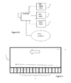
- FIG. 2A is a schematic block diagram of a control system for controlling operation of the sequencing of delay between actuating each chamber in the apparatus in FIGS. 1-2 .
- FIG. 3 is a top view of one example embodiment of a wave generator apparatus in a wave pool showing the direction that the wave may travel;
- FIGS. 4-5 are top views of one example embodiment of a wave generator apparatus in a wave pool showing multiple directions that the wave can flow depending on the amount of delay in the sequence;
- FIG. 6 is a view from the beach side or the side opposite the wave generating chambers of the pool. It shows the progression of the wave as it flows and how the height increases at various instances.
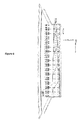
- FIG. 7 is a top view of one example embodiment of a wave generator apparatus in a wave pool with the side wall extending beyond the wave generating chambers.
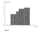
- FIG. 8 is a modeling graph showing the size of the wave and the amount of time it takes the wave to reach that size.
- the wave size is for a wave using sequencing. The measurements were taken using a small-scale version of the apparatus with nine chambers.
- the apparatus disclosed herein in various example embodiments provides a sequenced chamber wave generating apparatus that may be adapted for use with aquatic board sports or any other suitable purpose, such as miniature modeling of wave formations.
- the apparatus overcomes the deficiencies in the prior art by creating rideable waves that travel in a direction that is not perpendicular to the wave generating apparatus such that the wave strength continues to be replenished as the waves move across the pool.
- FIG. 1 illustrates an example embodiment of a wave generator apparatus, which comprises a pool or container 50, a body of water 52, a plurality of wave generating chambers 54 (each chamber is individually numbered 1-16), and a controller 62 to operate the chambers 54.
- a wave generator apparatus which comprises a pool or container 50, a body of water 52, a plurality of wave generating chambers 54 (each chamber is individually numbered 1-16), and a controller 62 to operate the chambers 54.
- there is no specifically required number of wave generating chambers 54 other example embodiments include twenty-four and thirty-two chambers
- too few chambers 54 in the apparatus may not be able to produce enough slices to create a wave that can be ridden.
- each chamber is 10 ft x 5 ft x 3 ft, giving each chamber a capacity of 150 cubic feet.
- Other example embodiments may have wave generating chambers as big as 260 cubic feet or more; but it would be
- the pool 50 may be rectangular shaped and holds the body of water 52.
- the pool 50 has a first end 58, a second end 60, two sides 44, 46, and a floor 36.
- the first end 58 is comprised of a plurality of chambers 54 adjacent to one another and the second end 60 is at the opposite end of the pool where the beach 42 is located.
- the two sides 44, 46 are at opposite ends of the pool 50.
- the first end 58, second end 60, and two sides 44, 46 act as walls for to pool 50 to contain the body of water 52 along with the floor 36 that is under the body of water 52.
- the body of water 52 rests in the pool 50 and is in a still state until the chambers 54 begin to actuate in sequence and create a wave using the body of water 52 in the pool 50.
- FIG. 2 illustrates an example embodiment of a single wave generating chamber 54, which can comprise of a chamber space 56 having a back wall 18, an upper wall 20, and a reflecting wall 22 at the rear wall of the pool that faces the body of water 52 in the pool 50.
- a single wave generating chamber 54 which can comprise of a chamber space 56 having a back wall 18, an upper wall 20, and a reflecting wall 22 at the rear wall of the pool that faces the body of water 52 in the pool 50.
- An example may be that of U.S. Pat. No. 7,815,396 to McFarland , the same inventor of the present application, and the contents of that patent are incorporated herein by reference.
- a passageway 30 at the lower end of wall 22 allows communication between the chambers 54 and the body of water 52 in the pool.
- a mechanical two-way valve 24 may be located in passageway 30.
- the chambers 54 may be connected to an air supply through inlet valve 26 located close to the upper end of the chamber back wall 18 and is also connected to a vent valve 28 in the upper wall 32, which may be connected to a vacuum pump.
- the floor 36 of the pool may have a first, upwardly inclined portion 38 extending from passageway 30 away from the wave reflecting wall 22, a generally flat portion 40, and an upwardly inclined portion or beach 42 at the opposite, second end 60 of the pool 50.
- the chamber 54 is first filled with air through valve 26, thereby displacing water into the pool 50.
- Valve 26 is then closed and the chamber air is vented suddenly through vent valve 28, causing the water 52 to flow from the pool 50 through passageway 30 into the now empty space 56 in the chamber 54.
- the water level in pool drops suddenly, creating a depression or trough in the water that reflects against the back or wave reflecting wall 22 of the pool 50. This creates a circulating motion of the water, which is enhanced by the design of the back wall.
- the vent valve 28 in the air chamber is shut at the proper time to prevent immediate water resurgence back into the pool 50, which enhances the second trough behind the peak.
- the mechanical two-way valve 24 can also be used to prevent immediate res resignation.
- the water valve 24 may be closed during the initial air fill phase to create a larger air volume in the chamber which, when released, creates a larger depression in the pool.
- air valve 26 can rapidly supply pressurized air to the chamber after the chamber is filled with water to push water out and amplify the wave peak. This process of pushing water out of the chamber and into the pool is known as releasing water.
- vent valve 28 may be connected to a vacuum source such as a vacuum pump, or may be a vent outlet connected via suitable valving either to atmosphere or to a vacuum source.
- the electronic controller 62 may be connected to the valves 26, 28 and 24 in order to control the operation in the manner described above.
- the controller 62 controls this operation for each chamber, such that the controller 62 actuates each of the chambers in sequence.
- the controller 62 may begin by actuating the first chamber in the plurality. After a delay, the controller 62 actuates the second chamber in the plurality, and, after a delay, actuates the third chamber in the plurality. This may continue for a fourth chamber or any number of additional chambers.
- the controller 62 continues actuating each chamber in the plurality after a delay.
- FIG. 2A illustrates that the controller 62 controls the valves in each chamber so that after actuating the first chamber it can control the valves in that chamber and, after as delay, actuate the second chamber and control its valves.
- the controller 62 can actuate each chamber in sequence after a delay and control the valves.
- the wave generator apparatus has the ability to create waves where the peak of the wave travels in a direction that is not substantially perpendicular to the ends of the pool and the chambers, as illustrated in FIG. 3 .
- the peak of the wave is defined as the highest water level in the pool.
- the direction the peak travels is the path that the peak of the wave flows during the life of the wave.
- the wave peak may continue to travel in a direction that is not perpendicular to the chambers 54.
- the controller 62 may actuate the chambers 54 in a sequence with a delay between actuating each chamber, as described above.
- the delay is approximately a fraction of the chamber period.
- sixteen chambers 1-16 are used to produce a wave that can be ridden and the peak travels not substantially perpendicular to the chambers 54 in direction A.
- the sequence starts with chamber 1 and continues sequentially (in lowest to highest numerical order of the chambers) down the plurality of chambers, which determines the direction of the wave.
- the wave breaks nearly right out of the chamber, and the break of the wave allows the peak to travel in a direction not substantially perpendicular to the chambers. Thus, a rider is able to ride the wave over much of the pool's water surface area.
- the peak continues until it reaches the side 44 of the pool 50. Although the path that the peak of the wave travels is not exactly parallel to the chambers 54, the pool may be constructed such that the peak may reach the side wall 44 before the peak could reach the opposite, beach end 42 of the pool.
- the apparatus replenishes the wave to continue its momentum such that the wave can continue to be ridden.
- a chamber 54 Immediately after a chamber 54 is activated, it creates a trough in the body of water 52 by allowing the water to enter the chamber space 56. The trough is created outside of the chamber 54 where the water entered the chamber 54. When the chamber 54 pushes or releases the water out to create a wave, the water flows into the area previously vacated and is now a trough. The sequencing allows the wave to travel not substantially perpendicular to the chamber 54 and break to create a wave.
- the fraction of delay between actuating each chamber may be proportional to the chamber period.
- the chamber period is the time it takes a chamber to release the water and refill to the predetermined level.
- the chamber 54 may permit a fixed amount of water, if any, to reenter the chamber 54.
- the controller operation may actuate each chamber, using a delay, in sequenced fashion. For example, while chamber 1 is in the wave production portion of its period, the controller 62 actuates chamber 2 and it begins its period. This sequence is repeated with each chamber using the same delay, with the controller 62 operating the sequencing.
- the controller operates the sequenced fashion or sequencing, which comprises each chamber in the plurality actuating after a delay and completing a chamber period.
- the fraction of the chamber period that is used as the delay by the controller 62 is approximately between 0.75 and 0.10.
- the amount of delay in the sequence can be adjusted within this range to adjust the amplitude of the wave and the direction the peak may travel. Also, the delay may vary between adjacent chambers.
- a delay of 0.25 can create a wave traveling in direction A as illustrated in FIG. 3 .
- the 0.25 delay means that the controller 62 may actuate chamber 2 when chamber 1 has completed 0.25 of its chamber period. Likewise, the controller 62 may actuate chamber 3 when chamber 2 has completed 0.25 of its chamber period. This delay may continue in the entire sequence.
- the subsequent chamber can activate in the sequence. This allows the wave to continue in the desired direction A.
- each chamber period is completed in four seconds. Therefore, the delay in the sequence would be set at one second, which is 0.25 of the chamber period.
- a new wave can then be produced using the same sequence. While this example uses 0.25 of the chamber period as the delay in the sequence, similar waves can be created with timing delays that are sequenced to actuate a chamber 54 when the previous chamber 54 is in the process of the wave generating phase of the chamber period.
- the amplitude or height of the peak of the wave created generally depends on the size of the wave generating apparatus.
- the peak traveling in direction A has an amplitude of nearly twice that of the peak traveling perpendicular to the chambers 54 in direction C.
- the peak of the wave may increase as it builds through the first few chambers in the sequence until it reaches its maximum height. For example, using the example embodiment in FIGS. 1 , 3 , with chambers 54 that are 150 cubic feet, the wave reaches about six feet in height.
- a wave without sequencing that travels in a direction perpendicular to the wave generating chambers 54, in direction C may reach a height of about three feet.
- a trough is created at 0.5 seconds, and the wave dramatically starts to build at 0.75 seconds, which is roughly when the third chamber is actuated.
- the wave has a peak of 2 inches at this point, which is a dramatic increase from 0.5 seconds when the wave size was 0 inches.
- the wave starts to crest just past the third chamber, when the peak reaches 2.5 inches.
- the wave's peak height ens to 3 inches when it reaches the fourth chamber. This occurs at 1.5 seconds, which coincides with when the sixth chamber is actuated by the controller 62.
- the peak reaches its maximum height of 3.2 inches.
- a wave traveling perpendicular to the chambers 54 has a maximum peak height of only 2 inches.
- the wave increases in height as it continues to flow and the chambers 54 continue to push the wave.
- the wave size increases as a result of each chamber 54 releasing water into the pool, which pushes into the same piece of wave, causing it to amplify.
- the same piece of wave is pushed when the each chamber actuates. This process continues through the beginning portion of the sequence or first few chambers until the wave reaches its maximum height. If there are too few chambers 54, the wave may not be smooth enough to ride. Likewise, if the chambers 54 produce a wave too big, it may be too choppy and not smooth enough to ride.
- the direction of the peak is determined by the delay in the sequencing of the chambers.
- FIG. 4 illustrates the different directions the peak can travel depending on the delay between the chambers. For example, if there is no delay and each chamber 54 actuates at the same time, the peak may travel perpendicular to the chambers in direction C towards the beach 42. When the controller 62 uses sequencing for a delay between each chamber 54, the peak may travel in more of an angled direction in order of the sequence.
- the sequence starts with chamber 1 actuating, then chamber 2, then chamber 3, and continuing down the plurality of chambers 54 until chamber 16 actuates. The peak may flow towards side 44 when this sequence continues.
- An increase in the delay sequence may cause the peak to travel in a direction that is more angled towards side 44. For example, a shortened delay in the sequence would result in the peak traveling in direction B, which flows more towards side 44. When increasing the delay even more, the peak can travel not substantially perpendicular to the chambers 54 towards side 44 in direction A.
- the peak can also travel in the other direction towards side 46. To do so, the sequence would have to start at chamber 16 and end at chamber 1. A shortened delay between the controller 62 actuating the chambers may result in the peak traveling in somewhat of an angle towards side 46, in direction E. A longer delay between the controller 62 actuating the chambers can result in the peak traveling not substantially perpendicular to the chambers in direction D, towards side 46. Also, chambers 16 and 1 could be actuated at the same time, then the adjacent chamber actuated after a delay, and so on, such that two wave peaks are created one moving in direction D ( Fig. 5 ) and one moving in direction A ( Fig. 4 ).
- FIG. 7 illustrates an example embodiment where the pool 52 extends beyond the chambers 54. This allows the wave to continue to travel after the sequence is complete, thus allowing a rider more time to ride the created wave.
- an aquatic sports amusement apparatus can comprise: a pool which holds a body of water, the pool having a first and second end, two sides, and a floor; a plurality of wave generating chambers that communicate with the body of water so as to release water into the pool, the chambers located adjacent to each other on one of the ends of the pool; each of the plurality of chambers having a valve structure, wherein each valve structure is connected to a controller wherein the connection is constructed to allow for the actuation of the each valve structure independently of the other valve structures; and the controller operates each valve structures independently, the operation can comprise the steps of: actuating each valve structure in a sequenced fashion to release water into the pool from each chamber in the plurality; creating a wave, wherein the wave comprises a peak defined as the highest water level in the pool; and traveling the peak in a direction that is not substantially perpendicular to the ends of the pool.
- the controller operation can comprise the following steps: a. actuating the valve structure of a first chamber in the plurality to release water into the pool; b. after a delay, actuating the valve structure of a second chamber in the plurality to release water into the pool; and c. after a delay, actuating the valve structure of a third chamber in the plurality to release water into the pool.
- the controller operation further can comprise the following steps: d. after the first chamber has released its water, actuating the valve structure of the first chamber to refill the first chamber with water to a predetermined level, wherein the time to release the water and refill to the predetermine level is defined as the chamber period; wherein the delay of steps (b) and (c) is a fraction of the chamber period and the fraction is 0.10 - 0.75.
- the delay in step (b) is of a different length than the delay in step (c).
- the controller operation can further comprise the following steps: after the first chamber has released its water, actuating the valve structure of the first chamber to refill the first chamber with water to a predetermined level, wherein the time to release the water and refill to the predetermine level is defined as the chamber period; wherein the delay of steps (b) and (c) is selected to adjust the travel direction of the peak of the wave.
- the controller operation can further comprise the following steps: after the first chamber has released its water, actuating the valve structure of the first chamber to refill the first chamber with water to a predetermined level, wherein the time to release the water and refill to the predetermine level is defined as the chamber period; wherein the delay of steps (b) and (c) is a fraction of the chamber period and the fraction is selected to adjust the amplitude of the wave peak.
- the floor of the pool is inclined.
- the pool length is longer than the plurality of the chambers, wherein the peak of the wave may travel and can continue to be ridden beyond the chambers.
- valve structure of each of the plurality of chambers comprises an air valve and a vent valve, wherein step (a) further comprises filing the chamber with air through the air valve, and wherein step (d) further comprises closing the air valve and opening the vent valve.
- the air valve and vent valve comprise a single two way valve.
- a method of generating waves in a pool of water can comprise: providing a pool which holds a body of water, the pool having: a plurality of wave generating chambers that communicate with the body of water so as to release water into the pool, the chambers located adjacent to each other on an edge of the of the pool; each of the plurality of chambers having a valve structure, wherein each valve structure is connected to a controller wherein the connection is constructed to allow for the actuation of the each valve structure independently of the other valve structures; a.
- valve structure of a first chamber in the plurality to release water into the pool and during step (a) the valve structures of a second and third chambers of the plurality are actuated so as to prevent the release water into the pool; b. after a delay, actuating the valve structure of a second chamber in the plurality to release water into the pool and during step (b) the valve structures of the first and third chambers of the plurality are actuated so as to prevent the release water into the pool; and c. after a delay, actuating the valve structure of a third chamber in the plurality to release water into the pool and during step (c) the valve structures of the first and second chambers of the plurality are actuated so as to prevent the release water into the pool.
- the sequenced fashion can comprise: after the first chamber has released its water, refilling the first chamber with water to a predetermined level, wherein the time to release the water and refill to the predetermine level is defined as the chamber period; wherein the delay of steps (b) and (c) is a fraction of the chamber period and the fraction of each delay is 0.10 - 0.75.
- the fraction of the chamber period for each chamber is selected to adjust the amplitude of the peak.
- the fraction of the chamber period for each chamber is selected to adjust the direction of the peak.
- the delay in step (b) is of a different length than the delay in step (c).
- an aquatic sports amusement apparatus can comprise: a pool; a plurality of wave generating chambers that communicate with the pool so as to release water into the pool; each of the plurality of chambers having a valve structure, wherein each valve structure is connected to a controller wherein the connection is constructed to allow for the actuation of each valve structure independently of the other valve structures; and the controller operates each valve structure independently, the operation comprising the steps of: a. actuating the valve structure of a first chamber or valve structures or a first set of chambers in the plurality to release water into the pool, during step (a) the valve structure of a second chamber or the valve structures of a second set of chambers of the plurality are actuated so as to prevent the release water into the pool; and b.
- valve structure of a second chamber or the valve structures of a second set of chambers in the plurality to release water into the pool
- step (b) the valve structure of the first chamber or the valve structures of the first set of chambers of the plurality are actuated so as to prevent the release water into the pool; and wherein the release of water into the pool creates a wave that can be ridden by a user.
- the controller operation can further comprise the following steps: c. after a delay, actuating the valve structure of a third chamber or the valve structures of third set of chambers in the plurality to release water into the pool, during step (c) the valve structure of the first and second chambers or the valve structures of the first and second sets of chambers of the plurality are actuated so as to prevent the release water into the pool.
- the controller operation can further comprise the following steps: d. after a delay, actuating the valve structure of any subsequent chamber or valve structures of any subsequent set of chambers in the plurality to release water into the pool, during step (d) the valve structure of the first, second and third chambers or the valve structures of the first, second and third sets of chambers of the plurality are actuated so as to prevent the release water into the pool.
Landscapes
- Engineering & Computer Science (AREA)
- Architecture (AREA)
- Civil Engineering (AREA)
- Structural Engineering (AREA)
- Revetment (AREA)
- Aerodynamic Tests, Hydrodynamic Tests, Wind Tunnels, And Water Tanks (AREA)
- Other Liquid Machine Or Engine Such As Wave Power Use (AREA)
Applications Claiming Priority (1)
| Application Number | Priority Date | Filing Date | Title |
|---|---|---|---|
| US13/411,520 US8434966B1 (en) | 2012-03-03 | 2012-03-03 | Sequenced chamber wave generator apparatus and method |
Publications (3)
| Publication Number | Publication Date |
|---|---|
| EP2634327A2 true EP2634327A2 (fr) | 2013-09-04 |
| EP2634327A3 EP2634327A3 (fr) | 2013-10-30 |
| EP2634327B1 EP2634327B1 (fr) | 2014-07-16 |
Family
ID=47779965
Family Applications (1)
| Application Number | Title | Priority Date | Filing Date |
|---|---|---|---|
| EP13157612.6A Active EP2634327B1 (fr) | 2012-03-03 | 2013-03-04 | Appareil générateur d'ondes de chambre séquentielles et procédé |
Country Status (3)
| Country | Link |
|---|---|
| US (1) | US8434966B1 (fr) |
| EP (1) | EP2634327B1 (fr) |
| CA (1) | CA2803379C (fr) |
Cited By (2)
| Publication number | Priority date | Publication date | Assignee | Title |
|---|---|---|---|---|
| CN111491702A (zh) * | 2017-12-21 | 2020-08-04 | 美国波浪机械公司 | 造波装置的改进 |
| US11534672B2 (en) | 2016-11-08 | 2022-12-27 | Ka'ana Wave Company Inc. | Wave producing method and apparatus |
Families Citing this family (9)
| Publication number | Priority date | Publication date | Assignee | Title |
|---|---|---|---|---|
| US9279263B2 (en) * | 2012-03-03 | 2016-03-08 | Bruce McFarland | Sequenced chamber wave generator apparatus and method |
| US11478719B2 (en) * | 2012-11-01 | 2022-10-25 | American Wave Machines, Inc. | Sequenced chamber wave generator controller and method |
| US10119285B2 (en) | 2017-01-20 | 2018-11-06 | The Wave Pool Company, LLC | Systems and methods for generating waves |
| US10760290B1 (en) | 2020-02-10 | 2020-09-01 | Walter Judson Bennett | Plunger wave making apparatus |
| WO2021159200A1 (fr) | 2020-02-14 | 2021-08-19 | Whitewater West Industries Ltd. | Générateur de vagues de piscine |
| US12404688B2 (en) | 2020-05-18 | 2025-09-02 | Whitewater West Industries Ltd. | Return channel for a surf pool |
| EP4153827A4 (fr) | 2020-05-18 | 2024-07-17 | Whitewater West Industries Ltd | Générateur à vagues sur piscine |
| MX2023009975A (es) * | 2021-02-25 | 2023-11-22 | Whitewater West Ind Ltd | Cámara y sistema de control y método para generar olas. |
| CN120457261A (zh) | 2022-10-19 | 2025-08-08 | 白水西部工业有限公司 | 用于造浪系统的蝶式风机进气与腔室排气阀控制器 |
Citations (4)
| Publication number | Priority date | Publication date | Assignee | Title |
|---|---|---|---|---|
| JPH0437314A (ja) | 1990-06-01 | 1992-02-07 | Mitsubishi Electric Corp | 分周回路 |
| JPH05202626A (ja) | 1992-01-28 | 1993-08-10 | Mitsubishi Heavy Ind Ltd | レジャースポーツ用造波プール |
| US6920651B2 (en) | 2003-06-05 | 2005-07-26 | Michael Kevin Roberts | Surfing ring wave pool for generating multiple simultaneous endless traveling waves looping around a center island |
| US7815396B2 (en) | 2006-10-04 | 2010-10-19 | American Wave Machines, Inc. | Reflecting wave generator apparatus and method |
Family Cites Families (30)
| Publication number | Priority date | Publication date | Assignee | Title |
|---|---|---|---|---|
| US2406413A (en) | 1941-11-29 | 1946-08-27 | Skiles E Test | Terraced combination pool and reservoir |
| US3105456A (en) | 1954-08-09 | 1963-10-01 | Aerojet General Co | Pressure wave generator |
| US3350724A (en) | 1964-07-07 | 1967-11-07 | Walter J Leigh | Method and apparatus for generating artificial waves in a body of water |
| FR1580805A (fr) | 1967-03-08 | 1969-09-12 | ||
| US3473334A (en) | 1968-06-24 | 1969-10-21 | Phillip Dexter | Apparatus and method for producing waves |
| US3629877A (en) | 1969-08-07 | 1971-12-28 | Siegfried A Schuster | Method and apparatus for wave formation in swim pools |
| US4062192A (en) * | 1974-06-03 | 1977-12-13 | Offshore Technology Corporation | Method of and mechanism for generating waves suitable for surfing |
| US4276664A (en) | 1979-01-30 | 1981-07-07 | Baker William H | Apparatus for wave-making |
| NL8203906A (nl) | 1982-10-08 | 1984-05-01 | Handelsmaatschappij Edoch B V | Pneumatische golfopwekker. |
| US4558474A (en) | 1982-10-08 | 1985-12-17 | Ecopool Design Limited | Wave generator |
| US4522535A (en) * | 1983-08-08 | 1985-06-11 | Ecopool Design Limited | Surf wave generator |
| US4515500A (en) * | 1983-11-15 | 1985-05-07 | Ecopool Design Limited | Combustion powered wave generator |
| US4730807A (en) | 1983-11-30 | 1988-03-15 | Wavetek International, Inc. | Surf pool gate valve |
| USRE34407E (en) | 1984-11-22 | 1993-10-12 | Light Wave, Ltd. | Water sports apparatus |
| GB8805480D0 (en) | 1988-03-08 | 1988-04-07 | Chutter G P | Apparatus for generating waves in swimming pool |
| US4692949A (en) | 1985-12-11 | 1987-09-15 | Wavetek International, Inc. | High-head, low-volume surfing wave pool |
| US4730355A (en) | 1986-05-08 | 1988-03-15 | Kreinbihl Mark L | Pneumatic wave generator employing four-way valve arrangement |
| US4812077A (en) | 1987-12-17 | 1989-03-14 | The Great Wave Company, Inc. | Pneumatic/hydraulic wave generator |
| US4979244A (en) | 1988-05-23 | 1990-12-25 | Dirk Bastenhof | Wave valve |
| US5098222A (en) | 1989-10-02 | 1992-03-24 | Wet Design | Wave generator |
| JP2913834B2 (ja) * | 1990-09-04 | 1999-06-28 | ライト ウエーブ,リミテッド. | ウォーターライドアトラクション装置 |
| WO1992014926A1 (fr) | 1991-02-14 | 1992-09-03 | Alan Keith Vowles | Generatrice d'energie d'origine ondulatoire |
| US5186578A (en) | 1991-09-20 | 1993-02-16 | Space Biospheres Venture | Wave generator |
| US5342145A (en) | 1993-04-21 | 1994-08-30 | Cohen Albert D | System for producing surfing waves for tube riding or wind surfing |
| US5621925A (en) * | 1995-03-03 | 1997-04-22 | Bastenhof; Dirk | Pool or water tank, such as a swimming pool, provided with means generating waves |
| US5535702A (en) | 1995-04-03 | 1996-07-16 | Idbeis; Badr | Aquarium sea current generator |
| US6475095B1 (en) | 1999-08-06 | 2002-11-05 | Nbgs International, Inc. | Amusement park water lock system and method of use |
| US6912738B2 (en) | 1999-12-13 | 2005-07-05 | Kerry Peter Black | Wave pool construction |
| AU2002226894C1 (en) | 2000-11-16 | 2012-09-20 | Thomas J. Lochtefeld | Method and apparatus for a wave pools |
| US6729799B1 (en) | 2001-09-28 | 2004-05-04 | George W. Raike | Pneumatic wave generator |
-
2012
- 2012-03-03 US US13/411,520 patent/US8434966B1/en active Active
-
2013
- 2013-01-24 CA CA2803379A patent/CA2803379C/fr active Active
- 2013-03-04 EP EP13157612.6A patent/EP2634327B1/fr active Active
Patent Citations (4)
| Publication number | Priority date | Publication date | Assignee | Title |
|---|---|---|---|---|
| JPH0437314A (ja) | 1990-06-01 | 1992-02-07 | Mitsubishi Electric Corp | 分周回路 |
| JPH05202626A (ja) | 1992-01-28 | 1993-08-10 | Mitsubishi Heavy Ind Ltd | レジャースポーツ用造波プール |
| US6920651B2 (en) | 2003-06-05 | 2005-07-26 | Michael Kevin Roberts | Surfing ring wave pool for generating multiple simultaneous endless traveling waves looping around a center island |
| US7815396B2 (en) | 2006-10-04 | 2010-10-19 | American Wave Machines, Inc. | Reflecting wave generator apparatus and method |
Cited By (3)
| Publication number | Priority date | Publication date | Assignee | Title |
|---|---|---|---|---|
| US11534672B2 (en) | 2016-11-08 | 2022-12-27 | Ka'ana Wave Company Inc. | Wave producing method and apparatus |
| CN111491702A (zh) * | 2017-12-21 | 2020-08-04 | 美国波浪机械公司 | 造波装置的改进 |
| CN111491702B (zh) * | 2017-12-21 | 2021-03-05 | 美国波浪机械公司 | 造波装置的改进 |
Also Published As
| Publication number | Publication date |
|---|---|
| EP2634327B1 (fr) | 2014-07-16 |
| CA2803379A1 (fr) | 2013-09-03 |
| US8434966B1 (en) | 2013-05-07 |
| EP2634327A3 (fr) | 2013-10-30 |
| CA2803379C (fr) | 2014-05-27 |
Similar Documents
| Publication | Publication Date | Title |
|---|---|---|
| EP2634327B1 (fr) | Appareil générateur d'ondes de chambre séquentielles et procédé | |
| US9279263B2 (en) | Sequenced chamber wave generator apparatus and method | |
| US7285053B2 (en) | Water amusement system and method | |
| US10233660B2 (en) | Apparatus for producing waves for surfing using staggered wave generators extended along a curved stagger line | |
| CA2831790C (fr) | Systeme et procede pour produire des vagues dans des directions multiples | |
| US9649569B2 (en) | Wave simulator for board sports | |
| JP3138979B2 (ja) | 単一容器内のシート水流ウォーターライドの方法及びその装置 | |
| DE69114013T3 (de) | Wellenreiten attraktion. | |
| EP1604712A1 (fr) | Système et methode d'amusement aquatique | |
| CN109923318A (zh) | 波浪产生方法和设备 | |
| WO2014074664A1 (fr) | Procédé et appareil de production de vagues appropriées pour le surf utilisant de générateurs de vague étalée étendus le long d'une ligne d'étalage incurvée | |
| US20100011497A1 (en) | Water feature for wave pools | |
| US8166582B2 (en) | Generated wave propulsion water feature | |
| US20060128487A1 (en) | Generated wave propulsion water feature | |
| HK1191991B (en) | System and method for generating waves in multiple directions | |
| HK1191992A (en) | System and method for generating waves in multiple directions |
Legal Events
| Date | Code | Title | Description |
|---|---|---|---|
| PUAI | Public reference made under article 153(3) epc to a published international application that has entered the european phase |
Free format text: ORIGINAL CODE: 0009012 |
|
| AK | Designated contracting states |
Kind code of ref document: A2 Designated state(s): AL AT BE BG CH CY CZ DE DK EE ES FI FR GB GR HR HU IE IS IT LI LT LU LV MC MK MT NL NO PL PT RO RS SE SI SK SM TR |
|
| AX | Request for extension of the european patent |
Extension state: BA ME |
|
| PUAL | Search report despatched |
Free format text: ORIGINAL CODE: 0009013 |
|
| AK | Designated contracting states |
Kind code of ref document: A3 Designated state(s): AL AT BE BG CH CY CZ DE DK EE ES FI FR GB GR HR HU IE IS IT LI LT LU LV MC MK MT NL NO PL PT RO RS SE SI SK SM TR |
|
| AX | Request for extension of the european patent |
Extension state: BA ME |
|
| RIC1 | Information provided on ipc code assigned before grant |
Ipc: A63G 31/00 20060101ALI20130926BHEP Ipc: A63B 69/12 20060101ALI20130926BHEP Ipc: E04H 4/00 20060101AFI20130926BHEP |
|
| 17P | Request for examination filed |
Effective date: 20131009 |
|
| RBV | Designated contracting states (corrected) |
Designated state(s): AL AT BE BG CH CY CZ DE DK EE ES FI FR GB GR HR HU IE IS IT LI LT LU LV MC MK MT NL NO PL PT RO RS SE SI SK SM TR |
|
| GRAP | Despatch of communication of intention to grant a patent |
Free format text: ORIGINAL CODE: EPIDOSNIGR1 |
|
| RIC1 | Information provided on ipc code assigned before grant |
Ipc: A63G 31/00 20060101ALI20140131BHEP Ipc: E04H 4/00 20060101AFI20140131BHEP Ipc: A63B 69/12 20060101ALI20140131BHEP |
|
| INTG | Intention to grant announced |
Effective date: 20140219 |
|
| GRAS | Grant fee paid |
Free format text: ORIGINAL CODE: EPIDOSNIGR3 |
|
| GRAA | (expected) grant |
Free format text: ORIGINAL CODE: 0009210 |
|
| AK | Designated contracting states |
Kind code of ref document: B1 Designated state(s): AL AT BE BG CH CY CZ DE DK EE ES FI FR GB GR HR HU IE IS IT LI LT LU LV MC MK MT NL NO PL PT RO RS SE SI SK SM TR |
|
| REG | Reference to a national code |
Ref country code: GB Ref legal event code: FG4D |
|
| REG | Reference to a national code |
Ref country code: CH Ref legal event code: EP |
|
| REG | Reference to a national code |
Ref country code: IE Ref legal event code: FG4D |
|
| REG | Reference to a national code |
Ref country code: AT Ref legal event code: REF Ref document number: 677774 Country of ref document: AT Kind code of ref document: T Effective date: 20140815 |
|
| REG | Reference to a national code |
Ref country code: DE Ref legal event code: R096 Ref document number: 602013000111 Country of ref document: DE Effective date: 20140828 |
|
| REG | Reference to a national code |
Ref country code: NL Ref legal event code: VDEP Effective date: 20140716 |
|
| REG | Reference to a national code |
Ref country code: AT Ref legal event code: MK05 Ref document number: 677774 Country of ref document: AT Kind code of ref document: T Effective date: 20140716 |
|
| REG | Reference to a national code |
Ref country code: LT Ref legal event code: MG4D |
|
| PG25 | Lapsed in a contracting state [announced via postgrant information from national office to epo] |
Ref country code: FI Free format text: LAPSE BECAUSE OF FAILURE TO SUBMIT A TRANSLATION OF THE DESCRIPTION OR TO PAY THE FEE WITHIN THE PRESCRIBED TIME-LIMIT Effective date: 20140716 Ref country code: BG Free format text: LAPSE BECAUSE OF FAILURE TO SUBMIT A TRANSLATION OF THE DESCRIPTION OR TO PAY THE FEE WITHIN THE PRESCRIBED TIME-LIMIT Effective date: 20141016 Ref country code: ES Free format text: LAPSE BECAUSE OF FAILURE TO SUBMIT A TRANSLATION OF THE DESCRIPTION OR TO PAY THE FEE WITHIN THE PRESCRIBED TIME-LIMIT Effective date: 20140716 Ref country code: LT Free format text: LAPSE BECAUSE OF FAILURE TO SUBMIT A TRANSLATION OF THE DESCRIPTION OR TO PAY THE FEE WITHIN THE PRESCRIBED TIME-LIMIT Effective date: 20140716 Ref country code: SE Free format text: LAPSE BECAUSE OF FAILURE TO SUBMIT A TRANSLATION OF THE DESCRIPTION OR TO PAY THE FEE WITHIN THE PRESCRIBED TIME-LIMIT Effective date: 20140716 Ref country code: PT Free format text: LAPSE BECAUSE OF FAILURE TO SUBMIT A TRANSLATION OF THE DESCRIPTION OR TO PAY THE FEE WITHIN THE PRESCRIBED TIME-LIMIT Effective date: 20141117 Ref country code: NO Free format text: LAPSE BECAUSE OF FAILURE TO SUBMIT A TRANSLATION OF THE DESCRIPTION OR TO PAY THE FEE WITHIN THE PRESCRIBED TIME-LIMIT Effective date: 20141016 Ref country code: GR Free format text: LAPSE BECAUSE OF FAILURE TO SUBMIT A TRANSLATION OF THE DESCRIPTION OR TO PAY THE FEE WITHIN THE PRESCRIBED TIME-LIMIT Effective date: 20141017 |
|
| PG25 | Lapsed in a contracting state [announced via postgrant information from national office to epo] |
Ref country code: LV Free format text: LAPSE BECAUSE OF FAILURE TO SUBMIT A TRANSLATION OF THE DESCRIPTION OR TO PAY THE FEE WITHIN THE PRESCRIBED TIME-LIMIT Effective date: 20140716 Ref country code: IS Free format text: LAPSE BECAUSE OF FAILURE TO SUBMIT A TRANSLATION OF THE DESCRIPTION OR TO PAY THE FEE WITHIN THE PRESCRIBED TIME-LIMIT Effective date: 20141116 Ref country code: PL Free format text: LAPSE BECAUSE OF FAILURE TO SUBMIT A TRANSLATION OF THE DESCRIPTION OR TO PAY THE FEE WITHIN THE PRESCRIBED TIME-LIMIT Effective date: 20140716 Ref country code: NL Free format text: LAPSE BECAUSE OF FAILURE TO SUBMIT A TRANSLATION OF THE DESCRIPTION OR TO PAY THE FEE WITHIN THE PRESCRIBED TIME-LIMIT Effective date: 20140716 Ref country code: AT Free format text: LAPSE BECAUSE OF FAILURE TO SUBMIT A TRANSLATION OF THE DESCRIPTION OR TO PAY THE FEE WITHIN THE PRESCRIBED TIME-LIMIT Effective date: 20140716 Ref country code: RS Free format text: LAPSE BECAUSE OF FAILURE TO SUBMIT A TRANSLATION OF THE DESCRIPTION OR TO PAY THE FEE WITHIN THE PRESCRIBED TIME-LIMIT Effective date: 20140716 Ref country code: CY Free format text: LAPSE BECAUSE OF FAILURE TO SUBMIT A TRANSLATION OF THE DESCRIPTION OR TO PAY THE FEE WITHIN THE PRESCRIBED TIME-LIMIT Effective date: 20140716 |
|
| REG | Reference to a national code |
Ref country code: DE Ref legal event code: R097 Ref document number: 602013000111 Country of ref document: DE |
|
| PG25 | Lapsed in a contracting state [announced via postgrant information from national office to epo] |
Ref country code: IT Free format text: LAPSE BECAUSE OF FAILURE TO SUBMIT A TRANSLATION OF THE DESCRIPTION OR TO PAY THE FEE WITHIN THE PRESCRIBED TIME-LIMIT Effective date: 20140716 Ref country code: DK Free format text: LAPSE BECAUSE OF FAILURE TO SUBMIT A TRANSLATION OF THE DESCRIPTION OR TO PAY THE FEE WITHIN THE PRESCRIBED TIME-LIMIT Effective date: 20140716 Ref country code: EE Free format text: LAPSE BECAUSE OF FAILURE TO SUBMIT A TRANSLATION OF THE DESCRIPTION OR TO PAY THE FEE WITHIN THE PRESCRIBED TIME-LIMIT Effective date: 20140716 Ref country code: SK Free format text: LAPSE BECAUSE OF FAILURE TO SUBMIT A TRANSLATION OF THE DESCRIPTION OR TO PAY THE FEE WITHIN THE PRESCRIBED TIME-LIMIT Effective date: 20140716 Ref country code: RO Free format text: LAPSE BECAUSE OF FAILURE TO SUBMIT A TRANSLATION OF THE DESCRIPTION OR TO PAY THE FEE WITHIN THE PRESCRIBED TIME-LIMIT Effective date: 20140716 Ref country code: CZ Free format text: LAPSE BECAUSE OF FAILURE TO SUBMIT A TRANSLATION OF THE DESCRIPTION OR TO PAY THE FEE WITHIN THE PRESCRIBED TIME-LIMIT Effective date: 20140716 |
|
| PLBE | No opposition filed within time limit |
Free format text: ORIGINAL CODE: 0009261 |
|
| STAA | Information on the status of an ep patent application or granted ep patent |
Free format text: STATUS: NO OPPOSITION FILED WITHIN TIME LIMIT |
|
| 26N | No opposition filed |
Effective date: 20150417 |
|
| PG25 | Lapsed in a contracting state [announced via postgrant information from national office to epo] |
Ref country code: LU Free format text: LAPSE BECAUSE OF FAILURE TO SUBMIT A TRANSLATION OF THE DESCRIPTION OR TO PAY THE FEE WITHIN THE PRESCRIBED TIME-LIMIT Effective date: 20150304 Ref country code: MC Free format text: LAPSE BECAUSE OF FAILURE TO SUBMIT A TRANSLATION OF THE DESCRIPTION OR TO PAY THE FEE WITHIN THE PRESCRIBED TIME-LIMIT Effective date: 20140716 |
|
| PG25 | Lapsed in a contracting state [announced via postgrant information from national office to epo] |
Ref country code: SI Free format text: LAPSE BECAUSE OF FAILURE TO SUBMIT A TRANSLATION OF THE DESCRIPTION OR TO PAY THE FEE WITHIN THE PRESCRIBED TIME-LIMIT Effective date: 20140716 |
|
| REG | Reference to a national code |
Ref country code: IE Ref legal event code: MM4A |
|
| PG25 | Lapsed in a contracting state [announced via postgrant information from national office to epo] |
Ref country code: IE Free format text: LAPSE BECAUSE OF NON-PAYMENT OF DUE FEES Effective date: 20150304 |
|
| REG | Reference to a national code |
Ref country code: FR Ref legal event code: PLFP Year of fee payment: 4 |
|
| PG25 | Lapsed in a contracting state [announced via postgrant information from national office to epo] |
Ref country code: BE Free format text: LAPSE BECAUSE OF FAILURE TO SUBMIT A TRANSLATION OF THE DESCRIPTION OR TO PAY THE FEE WITHIN THE PRESCRIBED TIME-LIMIT Effective date: 20140716 |
|
| REG | Reference to a national code |
Ref country code: CH Ref legal event code: PL |
|
| PG25 | Lapsed in a contracting state [announced via postgrant information from national office to epo] |
Ref country code: MT Free format text: LAPSE BECAUSE OF FAILURE TO SUBMIT A TRANSLATION OF THE DESCRIPTION OR TO PAY THE FEE WITHIN THE PRESCRIBED TIME-LIMIT Effective date: 20140716 |
|
| PG25 | Lapsed in a contracting state [announced via postgrant information from national office to epo] |
Ref country code: CH Free format text: LAPSE BECAUSE OF NON-PAYMENT OF DUE FEES Effective date: 20160331 Ref country code: LI Free format text: LAPSE BECAUSE OF NON-PAYMENT OF DUE FEES Effective date: 20160331 |
|
| REG | Reference to a national code |
Ref country code: FR Ref legal event code: PLFP Year of fee payment: 5 |
|
| PG25 | Lapsed in a contracting state [announced via postgrant information from national office to epo] |
Ref country code: HU Free format text: LAPSE BECAUSE OF FAILURE TO SUBMIT A TRANSLATION OF THE DESCRIPTION OR TO PAY THE FEE WITHIN THE PRESCRIBED TIME-LIMIT; INVALID AB INITIO Effective date: 20130304 |
|
| PG25 | Lapsed in a contracting state [announced via postgrant information from national office to epo] |
Ref country code: HR Free format text: LAPSE BECAUSE OF FAILURE TO SUBMIT A TRANSLATION OF THE DESCRIPTION OR TO PAY THE FEE WITHIN THE PRESCRIBED TIME-LIMIT Effective date: 20140716 |
|
| PG25 | Lapsed in a contracting state [announced via postgrant information from national office to epo] |
Ref country code: TR Free format text: LAPSE BECAUSE OF FAILURE TO SUBMIT A TRANSLATION OF THE DESCRIPTION OR TO PAY THE FEE WITHIN THE PRESCRIBED TIME-LIMIT Effective date: 20140716 |
|
| REG | Reference to a national code |
Ref country code: FR Ref legal event code: PLFP Year of fee payment: 6 |
|
| PG25 | Lapsed in a contracting state [announced via postgrant information from national office to epo] |
Ref country code: SM Free format text: LAPSE BECAUSE OF FAILURE TO SUBMIT A TRANSLATION OF THE DESCRIPTION OR TO PAY THE FEE WITHIN THE PRESCRIBED TIME-LIMIT Effective date: 20140716 |
|
| PG25 | Lapsed in a contracting state [announced via postgrant information from national office to epo] |
Ref country code: MK Free format text: LAPSE BECAUSE OF FAILURE TO SUBMIT A TRANSLATION OF THE DESCRIPTION OR TO PAY THE FEE WITHIN THE PRESCRIBED TIME-LIMIT Effective date: 20140716 |
|
| PG25 | Lapsed in a contracting state [announced via postgrant information from national office to epo] |
Ref country code: AL Free format text: LAPSE BECAUSE OF FAILURE TO SUBMIT A TRANSLATION OF THE DESCRIPTION OR TO PAY THE FEE WITHIN THE PRESCRIBED TIME-LIMIT Effective date: 20140716 |
|
| P01 | Opt-out of the competence of the unified patent court (upc) registered |
Effective date: 20230530 |
|
| PGFP | Annual fee paid to national office [announced via postgrant information from national office to epo] |
Ref country code: GB Payment date: 20260324 Year of fee payment: 14 |
|
| PGFP | Annual fee paid to national office [announced via postgrant information from national office to epo] |
Ref country code: DE Payment date: 20260217 Year of fee payment: 14 |
|
| PGFP | Annual fee paid to national office [announced via postgrant information from national office to epo] |
Ref country code: FR Payment date: 20260324 Year of fee payment: 14 |