EP2634350A2 - Joint amovible, notamment joint de porte coulissante - Google Patents
Joint amovible, notamment joint de porte coulissante Download PDFInfo
- Publication number
- EP2634350A2 EP2634350A2 EP20130157452 EP13157452A EP2634350A2 EP 2634350 A2 EP2634350 A2 EP 2634350A2 EP 20130157452 EP20130157452 EP 20130157452 EP 13157452 A EP13157452 A EP 13157452A EP 2634350 A2 EP2634350 A2 EP 2634350A2
- Authority
- EP
- European Patent Office
- Prior art keywords
- seal
- trigger
- housing
- leaf spring
- rod
- Prior art date
- Legal status (The legal status is an assumption and is not a legal conclusion. Google has not performed a legal analysis and makes no representation as to the accuracy of the status listed.)
- Granted
Links
Images


Classifications
-
- E—FIXED CONSTRUCTIONS
- E06—DOORS, WINDOWS, SHUTTERS, OR ROLLER BLINDS IN GENERAL; LADDERS
- E06B—FIXED OR MOVABLE CLOSURES FOR OPENINGS IN BUILDINGS, VEHICLES, FENCES OR LIKE ENCLOSURES IN GENERAL, e.g. DOORS, WINDOWS, BLINDS, GATES
- E06B7/00—Special arrangements or measures in connection with doors or windows
- E06B7/16—Sealing arrangements on wings or parts co-operating with the wings
- E06B7/18—Sealing arrangements on wings or parts co-operating with the wings by means of movable edgings, e.g. draught sealings additionally used for bolting, e.g. by spring force or with operating lever
- E06B7/20—Sealing arrangements on wings or parts co-operating with the wings by means of movable edgings, e.g. draught sealings additionally used for bolting, e.g. by spring force or with operating lever automatically withdrawn when the wing is opened, e.g. by means of magnetic attraction, a pin or an inclined surface, especially for sills
- E06B7/215—Sealing arrangements on wings or parts co-operating with the wings by means of movable edgings, e.g. draught sealings additionally used for bolting, e.g. by spring force or with operating lever automatically withdrawn when the wing is opened, e.g. by means of magnetic attraction, a pin or an inclined surface, especially for sills with sealing strip being moved to a retracted position by elastic means, e.g. springs
Definitions
- the present invention relates to a seal, in particular a sliding door seal with a housing, a sealing strip which can be lowered from a first position to a second position, with a mechanism which connects the sealing strip to the housing and the displacement of the sealing strip from the first position to the second position and vice versa, wherein the mechanism for displacing the sealing strip from the first position to the second position is operable and has a leaf spring for displacing the sealing strip from the second to the first position when the mechanism is not actuated, wherein a first end of the leaf spring relative to the housing is immovably connected to the same and the second end is slidably disposed in the housing, wherein in the region of the second end of the leaf spring connecting structures for connection to a first end of a rod are provided, wherein in the housing between the leaf spring and a a seal is provided on the outer side of the housing opposite the sealing strip, in which this rod is slidably accommodated, and wherein the channel extends from the second end of the leaf spring to the first end
- a leaf spring may have any cross section, in particular a rectangular, a circular, elliptical or triangular cross section.
- the leaf springs may be rods or rods or wires that are subjected to flexing.
- Such a seal with a rod, which is connected to the second end of the leaf spring, is from the publication with the publication number EP 2 085 559 A2 known.
- the seal can be released by pulling on the rod.
- the same document discloses a seal in which the trigger is connected to the rod.
- the housing has a recess in a longitudinal wall through which the trigger protrudes.
- the trigger of such a seal can basically be placed at various locations along the length of the rod. However, the location of the release of the trigger must already be determined during the manufacture of the seal. A subsequent change of the seal is not readily possible.
- a conventional seal as for example in the document EP 0 338 974 A1 is disclosed, to a seal with a projecting over the longitudinal housing wall trigger which is actuated by train, to a seal according to the document EP 2 085 559 A2 rebuild.
- EP 1 717 405 A1 and EP 0 509 961 A1 are seals known as the seal according to the document EP 0 338 974 A can be actuated by pressing a trigger, which projects beyond the housing of the seal. It is not possible to operate by pulling on the release button or by pulling and pressing on the release button.
- the invention has for its object to propose a seal that can be actuated both by means of a protruding on the front side of the housing, by pressing triggers to be operated, and as a seal with a laterally projecting beyond the longitudinal housing wall, by train to be operated trigger can be used.
- Such a seal can be used for example in a swing door, as for example from the publication EP 0 338 974 A1 is disclosed. However, such a seal can also be used in a sliding door, in which it may be desirable if the seal is actuated by pulling the trigger attached to the side opposite the lock side of the door leaf.
- a guide is provided in which a first, connectable to the rod first trigger can be slidably disposed, which is suitable and adapted to operate the mechanism.
- the designed according to claim 1 seal is incomplete insofar as it still has no trigger with which the seal can be actuated to bring the sealing strip from the first position to the second position.
- the seal according to claim 1 can be supplemented by adding at least one trigger to a seal that is suitable for everyday use.
- the seal according to claim 1 is designed so that at two different locations triggers can be mounted in order to come to a complete and functional seal.
- This first trigger is advantageously the trigger that is suitable and arranged to be actuated by train. But this does not rule out the possibility that the first trigger can also be actuated by pressure.
- the seal according to claim 1 is therefore prepared to be provided with a first trigger which can be operated as is advantageous for uses of seals on sliding doors.
- the gasket of claim 1 may also be completed by fitting a second trigger at a suitable location to a gasket used in a swing door in which the gasket is actuated by pressure on a trigger, as known in the art is.
- a second trigger for example, the second end of the leaf spring be connectable to a second trigger, which is also suitable and arranged for actuating the mechanism of the seal as the first mechanism.
- the first trigger or the second trigger can be used. It is also possible to use the first shutter and the second shutter simultaneously.
- a seal according to the invention may comprise a coupling piece which is connected to the second end of the spring and which has a connection structure for connection to the rod.
- a seal according to the invention may further comprise a connecting piece which connects the coupling piece of the seal with the second end of the leaf spring.
- the rod may be part of a seal according to the invention as well as the first trigger.
- the rod then extends in the channel of the housing.
- the first trigger may be slidably disposed in the guide at the first channel end or adjacent the first channel end. If necessary, the rod can connect the second end of the leaf spring and the first trigger via the coupling piece.
- the first trigger of a seal according to the invention can project beyond a longitudinal side of the housing. It is also possible that the first trigger protrudes beyond an end face of the housing.
- the housing of a seal according to the invention may have a recess in a wall on the longitudinal side of the housing and the first trigger may protrude through this recess and thus protrude beyond the longitudinal side of the housing.
- the first trigger may have a first coupling piece.
- the first coupling piece is not the same component as the already mentioned coupling piece of the seal.
- the first trigger may further include a cantilever and a spindle.
- the first coupling piece may have a threaded bore in which the spindle is screwed.
- the boom may be attached to the spindle and protrude beyond the longitudinal side of the housing.
- the first trigger in particular the first coupling piece of the first trigger may have a connection structure for connection to the rod.
- the coupling piece of the seal and the first coupling piece of the first trigger may be the same. This means in particular that the coupling piece of the seal and the first coupling piece have the same shape and are made of the same material.
- a seal according to the invention may have a second trigger instead of the first trigger or in addition to the first trigger.
- the second trigger may have a connector with a spindle and a second coupling piece.
- the second coupling piece may have a threaded bore in which the spindle is screwed.
- the connector may connect the trigger to the second end of the leaf spring.
- the second coupling piece is advantageously formed by the coupling piece of the seal.
- the second coupling piece and the coupling piece of the seal are thus advantageously one and the same component.
- the connector of the second trigger may be formed by the connector of the seal. These too would then be one and the same component.
- a particular seal according to the invention may comprise two leaf springs, each having a first end and a second end.
- the first end of the first leaf spring is indirectly or directly connected to the housing while the second end of the first leaf spring is directly or indirectly connected to the first end of the second leaf spring.
- the second end of the second leaf spring is slidably disposed in the housing. The second end of the second leaf spring takes over the functions of the second end of the leaf spring, if only a single leaf spring is used in the seal.
- leaf springs which are arranged lying between the first and the second leaf spring in the housing and connected to the first and the second leaf spring.
- a further invention further relates to a seal, in particular a sliding door seal with a housing, a sealing strip which can be lowered from a first position to a second position, with a mechanism which connects the sealing strip to the housing and the displacement of the sealing strip from the first position to the second Position and vice versa allows, with the Mechanism for displacing the sealing strip from the first position to the second position is operable and having a rod which extends within the housing from a first end portion at a first end side of the seal to a second end portion at a second end side of the seal, wherein by elements the mechanism is a longitudinal movement of the rod in a lowering movement of the sealing strip can be implemented and wherein at one end of the rod connecting structures are provided, to which a trigger can be attached.
- a seal in particular a sliding door seal with a housing, a sealing strip which can be lowered from a first position to a second position, with a mechanism which connects the sealing strip to the housing and the displacement of the sealing strip from the first position to the
- Such a seal with a pressure-actuatable trigger is for example from the document DE 34 27 928 A1 known.
- This seal is intended for a swing door and can only be operated by pressing the release button.
- a seal is also to be operated by train.
- Another object of the invention is to propose a seal which can be actuated both by conventional means by means of a trigger projecting from the housing on the front side and by a trigger to be actuated as well as a seal having a side projecting beyond the longitudinal housing wall Train to be operated trigger can be used.
- the train operable Trigger can be a boom or at least include a boom that protrudes laterally, upwards or downwards over the housing.
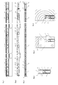
- the housing 1 has a uniform with the exception of some recesses cross-sectional profile and is substantially U-shaped, with a web 11 and substantially perpendicular to the web 11 extending legs 12. On the inside of the legs 12, two opposing ribs 13 are provided , In addition, the housing in extension to the legs 12 on the web 11 protruding ribs 14, whose ends are angled inward.
- the sealing strip has a retaining profile 3 and an elastomeric sealing profile 2, which is a seal between a door leaf T, at which the seal u. a. attached via an angle 4, and a floor, a ceiling or a frame allows.
- the mechanism of the first seal has two leaf springs 5a, 5b.
- a first of these leaf springs 5 a is connected to a first end 51 a via a holding member 30 fixed to the housing 1.
- the second end 52a of the first leaf spring 5a is slidably mounted in the longitudinal direction of the housing 1 of the seal.
- the second end 52 a of the leaf spring 5 a is pivotally connected to a first intermediate piece 10.
- the first intermediate piece 10 is positively connected to a second intermediate piece 20 which is positively connected to a further first intermediate piece 10.
- a first end 51 b of a second of the leaf springs 5 b is pivotally mounted, the second end 52 b is pivotally connected via yet another first intermediate piece 10 with a connecting piece 6.
- the connecting piece 6 has a spindle 61. This spindle 61 is screwed into a threaded bore of a coupling piece 7.
- the coupling piece 7 is slidably mounted in the housing 1 between the legs 12, the ribs 13 on the inner sides of the legs 12 and the web 11 of the housing 1.
- the first intermediate pieces 10 are preferably identical.
- the coupling piece 7 has a transverse bore. This transverse bore forms a connecting structure for connecting the coupling piece 7 with a rod 8, which is guided above the web 11 of the housing, in a channel formed by the web 11 and the ribs 14 in extension of the legs 12.
- the web 11 of the housing 1 has a slot 111 above the coupling piece.
- the slot 111 has a length which makes it possible for the transverse bore in the coupling piece 7 to be accessible from above at any position of the coupling piece 7 along its displacement path.
- the guided in the channel rod 8 is angled at both ends. The one end is inserted through the slot 111 above the coupling piece 7 of the seal and into the transverse bore of the coupling means 7. Upon a displacement of the rod 8 thus the coupling means 7 is taken.
- the rod 8 is guided to one end of the channel.
- a slot 112 is likewise provided in the web 11 of the housing 1. This slot 112 is penetrated by the angled other end of the rod 8.
- a first trigger 9 is slidably housed.
- This first trigger 9 has a first coupling piece 91 which is designed in the same way as the coupling piece 7 already mentioned.
- This first coupling piece 91 is in the region adjacent to the channel end between the web 11, the legs 12 and the ribs 13 on the inside of the Leg 12 out. This area forms a guide for the first coupling means 91 of the first trigger 9.
- the first coupling piece 91 like the already mentioned coupling piece 7, also has a transverse bore as a connecting structure for connection to the rod 8 into which the other angled end of the rod 8 is inserted.
- the first coupling piece 91 also has a longitudinally extending threaded bore, in which a spindle 92 is screwed, which, like a spindle 93 attached to the boom 93 is part of the first trigger 9.
- the boom 93 has a bore through which the spindle 92 is guided.
- the boom 93 is free to rotate on the spindle 92.
- cotter pins or threaded pins 94 the position of the cantilever 93 is fixed in the longitudinal direction of the spindle 92.
- opposing elongated holes are provided in the legs 12 of the housing 1.
- One of these elongated holes is penetrated by the extension arm 93, so that the extension arm 93 projects laterally beyond the longitudinal wall, i. one of the legs 12 of the housing 1 protrudes.
- the spindle 92 has at its free end a slot or a key surface on which a screwdriver or other suitable tool can be attached. By turning the spindle 92, it can be further screwed into the first coupling means 91. Thereby, the distance of the boom 93 to the first coupling means 91 can be adjusted, whereby the position of the protruding from the housing 1 part of the boom 93 can be adjusted.
- the coupling piece 7 of the seal and the connecting piece 6 at the second end 52b of the second leaf spring 5b may form a second trigger.
- the coupling piece 7 then forms a second coupling piece of the second trigger.
- the second coupling piece can for this purpose have a stop face, which protrudes beyond the front side of the housing of the seal when the seal is not actuated. Whether the second coupling piece protrudes beyond the end face of the housing and by what extent the coupling piece projects beyond the end face can be adjusted by a more or less deep screwing in of the spindle 61 of the connecting piece 6 into the coupling piece 7.
- the actuation of the first trigger 9 can be done for example by striking the boom on a frame Z of a sliding door, as shown in the FIGS. 8 and 9 is shown.
- the in the FIGS. 10 to 13 illustrated second seal also has a housing 1, a sealing strip 2, 3 with a holding profile 3 and a sealing profile 3.
- the retaining profile 2 is connected to a mechanism, not shown in detail, which is connected to the housing 1. By actuation of the mechanism, the sealing strip 2, 3 can be brought from a first position to a second position, as it is known from seals.
- the mechanism has a rod 8 which extends from one end to the other end in the housing. At the ends of the rod 8, a first trigger 9 and a second trigger 9a are mounted.
- the first trigger 9 protrudes with a boom 93 both over the front side of the housing 1 and on the longitudinal side of the housing 1 also. This first trigger 9 can be charged to train.
- the second trigger 9a projects beyond the front side of the housing 1 on the other side of the housing 1. This second trigger 9a can only be loaded under pressure to trigger the seal.
- the first trigger 9 is mounted on an envelope, so that, depending on the installation situation, the boom 93 can protrude beyond one or the other longitudinal side of the housing 1.
- the second seal may be achieved, for example, by abutting the cantilever 93 of the first trigger 9 on a stop element A, as shown in FIG FIG. 12 and the FIG. 13 is shown triggered.
Landscapes
- Engineering & Computer Science (AREA)
- Civil Engineering (AREA)
- Structural Engineering (AREA)
- Specific Sealing Or Ventilating Devices For Doors And Windows (AREA)
Applications Claiming Priority (1)
| Application Number | Priority Date | Filing Date | Title |
|---|---|---|---|
| DE202012100752U DE202012100752U1 (de) | 2012-03-02 | 2012-03-02 | Dichtung, insbesondere Schiebetürdichtung |
Publications (4)
| Publication Number | Publication Date |
|---|---|
| EP2634350A2 true EP2634350A2 (fr) | 2013-09-04 |
| EP2634350A8 EP2634350A8 (fr) | 2013-12-04 |
| EP2634350A3 EP2634350A3 (fr) | 2015-05-13 |
| EP2634350B1 EP2634350B1 (fr) | 2022-02-02 |
Family
ID=47779950
Family Applications (1)
| Application Number | Title | Priority Date | Filing Date |
|---|---|---|---|
| EP13157452.7A Active EP2634350B1 (fr) | 2012-03-02 | 2013-03-01 | Joint amovible, notamment joint de porte coulissante |
Country Status (2)
| Country | Link |
|---|---|
| EP (1) | EP2634350B1 (fr) |
| DE (1) | DE202012100752U1 (fr) |
Cited By (2)
| Publication number | Priority date | Publication date | Assignee | Title |
|---|---|---|---|---|
| JP2015527511A (ja) * | 2012-07-30 | 2015-09-17 | プラネット ゲーデーツェット アーゲー | ドロップダウンシール及び建物部分 |
| EP3085876A1 (fr) | 2015-04-20 | 2016-10-26 | Planet GDZ AG | Dispositif de joint descendant et unité de déclenchement |
Families Citing this family (4)
| Publication number | Priority date | Publication date | Assignee | Title |
|---|---|---|---|---|
| AU2013204514B2 (en) * | 2012-04-27 | 2016-06-02 | Raven Products Pty Ltd | Drop door seal and connectors for modular connecting rods |
| CN103867085A (zh) * | 2014-03-11 | 2014-06-18 | 江苏海陆科技股份有限公司 | 无障碍高隔声船用防火门升降密闭装置 |
| US11873677B2 (en) | 2021-09-28 | 2024-01-16 | Westhampton Architectural Glass, Inc. | Fenestration system with actuatable sealing device, and related devices, systems, and methods |
| DE202022102658U1 (de) | 2022-05-13 | 2022-05-30 | Athmer Ohg | Dichtung, insbesondere für Schiebetüren oder Schiebetore |
Citations (7)
| Publication number | Priority date | Publication date | Assignee | Title |
|---|---|---|---|---|
| DE1179692B (de) | 1959-06-12 | 1964-10-15 | Athmer Fa F | Abdichtungsvorrichtung fuer Tueren |
| DE3526720A1 (de) | 1984-07-28 | 1986-01-30 | Fa. F. Athmer, 5760 Arnsberg | Dichtungsvorrichtung fuer den unteren tuerspalt eines tuerfluegels |
| DE3427928C1 (de) | 1984-07-28 | 1986-03-13 | Mathis Systemtechnik GmbH, 7844 Neuenburg | Vorrichtung zum Verteilen von Schuettgut in einem Behaelter |
| EP0338974A2 (fr) | 1988-04-19 | 1989-10-25 | " Planet" Matthias Jaggi | Dispositif d'étanchéité pour portes sans seuil |
| EP0509961A1 (fr) | 1991-04-17 | 1992-10-21 | Planet MJT AG | Dispositif d'étanchéité, particulièrement pour battants de portes |
| EP1717405A1 (fr) | 2005-04-29 | 2006-11-02 | Ernst Keller GmbH & Co. KG | Dispositif d'étanchéité pour porte |
| EP2085559A2 (fr) | 2008-02-04 | 2009-08-05 | Planet GDZ AG | Dispositif d'étanchéité abaissable |
Family Cites Families (1)
| Publication number | Priority date | Publication date | Assignee | Title |
|---|---|---|---|---|
| WO2009155295A1 (fr) * | 2008-06-17 | 2009-12-23 | John B . Higman And Valorie J . Higman; Trustees Of The Higman Family Trust U/ D/T As Amended And Restated On December 22 , 2006 . | Porte et système de porte à scellement hermétique automatique |
-
2012
- 2012-03-02 DE DE202012100752U patent/DE202012100752U1/de not_active Expired - Lifetime
-
2013
- 2013-03-01 EP EP13157452.7A patent/EP2634350B1/fr active Active
Patent Citations (7)
| Publication number | Priority date | Publication date | Assignee | Title |
|---|---|---|---|---|
| DE1179692B (de) | 1959-06-12 | 1964-10-15 | Athmer Fa F | Abdichtungsvorrichtung fuer Tueren |
| DE3526720A1 (de) | 1984-07-28 | 1986-01-30 | Fa. F. Athmer, 5760 Arnsberg | Dichtungsvorrichtung fuer den unteren tuerspalt eines tuerfluegels |
| DE3427928C1 (de) | 1984-07-28 | 1986-03-13 | Mathis Systemtechnik GmbH, 7844 Neuenburg | Vorrichtung zum Verteilen von Schuettgut in einem Behaelter |
| EP0338974A2 (fr) | 1988-04-19 | 1989-10-25 | " Planet" Matthias Jaggi | Dispositif d'étanchéité pour portes sans seuil |
| EP0509961A1 (fr) | 1991-04-17 | 1992-10-21 | Planet MJT AG | Dispositif d'étanchéité, particulièrement pour battants de portes |
| EP1717405A1 (fr) | 2005-04-29 | 2006-11-02 | Ernst Keller GmbH & Co. KG | Dispositif d'étanchéité pour porte |
| EP2085559A2 (fr) | 2008-02-04 | 2009-08-05 | Planet GDZ AG | Dispositif d'étanchéité abaissable |
Cited By (3)
| Publication number | Priority date | Publication date | Assignee | Title |
|---|---|---|---|---|
| JP2015527511A (ja) * | 2012-07-30 | 2015-09-17 | プラネット ゲーデーツェット アーゲー | ドロップダウンシール及び建物部分 |
| EP2888428B1 (fr) * | 2012-07-30 | 2021-08-25 | ASSA ABLOY (Schweiz) AG | Joint descendant et élément de construction |
| EP3085876A1 (fr) | 2015-04-20 | 2016-10-26 | Planet GDZ AG | Dispositif de joint descendant et unité de déclenchement |
Also Published As
| Publication number | Publication date |
|---|---|
| EP2634350A3 (fr) | 2015-05-13 |
| EP2634350A8 (fr) | 2013-12-04 |
| EP2634350B1 (fr) | 2022-02-02 |
| DE202012100752U1 (de) | 2013-06-04 |
Similar Documents
| Publication | Publication Date | Title |
|---|---|---|
| DE102018129450B4 (de) | Türgarnitur mit einer einseitig verriegelbaren Handhabe | |
| EP2634350B1 (fr) | Joint amovible, notamment joint de porte coulissante | |
| EP3165703A2 (fr) | Dispositif d'étanchéité abaissable | |
| DE3005817C2 (de) | Schienenführung | |
| EP2474698A2 (fr) | Dispositif d'étanchéité doté d'un profil d'étanchéité et d'un mécanisme destiné au déplacement du profil d'étanchéité lors de l'actionnement du mécanisme | |
| EP3112577A1 (fr) | Joint abaissable | |
| EP3699386B1 (fr) | Joint automatique d'étanchéité de porte doté un moyen pour guider une tige de pousser et methode pour positioner ladite tige de pousser dans un bôtier pour ledit joint d'étanchéité | |
| DE102012200430B4 (de) | Schiebetüren- oder -fensteranlage mit mindestens zwei als Tür oder Fenster ausgebildeten Schiebeelementen sowie Verriegelungseinrichtung hierfür | |
| DE102008003565A1 (de) | Abdeckelement für eine Gleitschiene | |
| DE2660645C1 (de) | Eckumlenkung fuer Fensterbeschlaege | |
| EP1717405A1 (fr) | Dispositif d'étanchéité pour porte | |
| DE102013113915A1 (de) | Federklemmung mit Öffnungsbegrenzer | |
| EP2716844A2 (fr) | Verrou de porte | |
| DE202013006032U1 (de) | Spielfigur für insbesondere ein Tischfußballgerät | |
| DE20109265U1 (de) | Verriegelungsvorrichtung | |
| DE102012111364A1 (de) | Feststellvorrichtung für eine Tür, vorzugsweise mit Türschließer | |
| DE202009004463U1 (de) | Verschlusssystem mit einem auf der Verschlussstange beweglich angeordneten Federriegel | |
| EP1755519A1 (fr) | Support de bequille et bequille comprenant un tel support | |
| DE202008013792U1 (de) | Kombinationsschloss | |
| AT15236U1 (de) | Sperrbalken zur Absperrung eines Durchgangs | |
| DE102014217711B4 (de) | Kulissenanordnung für eine Beschlagteilanordnung | |
| DE29920508U1 (de) | Treibstangenschloss | |
| DE102013209411A1 (de) | Klemmverbindung | |
| DE102005030399B4 (de) | Flachbauendes Gurtschloss | |
| DE102014217713B4 (de) | Dichtungsstrang für eine Beschlagteilanordnung |
Legal Events
| Date | Code | Title | Description |
|---|---|---|---|
| PUAI | Public reference made under article 153(3) epc to a published international application that has entered the european phase |
Free format text: ORIGINAL CODE: 0009012 |
|
| AK | Designated contracting states |
Kind code of ref document: A2 Designated state(s): AL AT BE BG CH CY CZ DE DK EE ES FI FR GB GR HR HU IE IS IT LI LT LU LV MC MK MT NL NO PL PT RO RS SE SI SK SM TR |
|
| AX | Request for extension of the european patent |
Extension state: BA ME |
|
| RIN1 | Information on inventor provided before grant (corrected) |
Inventor name: FAFLEK, JENOE Inventor name: CRONENBERG, CARL-JULIUS |
|
| PUAL | Search report despatched |
Free format text: ORIGINAL CODE: 0009013 |
|
| AK | Designated contracting states |
Kind code of ref document: A3 Designated state(s): AL AT BE BG CH CY CZ DE DK EE ES FI FR GB GR HR HU IE IS IT LI LT LU LV MC MK MT NL NO PL PT RO RS SE SI SK SM TR |
|
| AX | Request for extension of the european patent |
Extension state: BA ME |
|
| RIC1 | Information provided on ipc code assigned before grant |
Ipc: E06B 7/215 20060101AFI20150407BHEP |
|
| 17P | Request for examination filed |
Effective date: 20151103 |
|
| RBV | Designated contracting states (corrected) |
Designated state(s): AL AT BE BG CH CY CZ DE DK EE ES FI FR GB GR HR HU IE IS IT LI LT LU LV MC MK MT NL NO PL PT RO RS SE SI SK SM TR |
|
| STAA | Information on the status of an ep patent application or granted ep patent |
Free format text: STATUS: EXAMINATION IS IN PROGRESS |
|
| 17Q | First examination report despatched |
Effective date: 20171208 |
|
| GRAP | Despatch of communication of intention to grant a patent |
Free format text: ORIGINAL CODE: EPIDOSNIGR1 |
|
| STAA | Information on the status of an ep patent application or granted ep patent |
Free format text: STATUS: GRANT OF PATENT IS INTENDED |
|
| INTG | Intention to grant announced |
Effective date: 20210830 |
|
| GRAS | Grant fee paid |
Free format text: ORIGINAL CODE: EPIDOSNIGR3 |
|
| GRAA | (expected) grant |
Free format text: ORIGINAL CODE: 0009210 |
|
| STAA | Information on the status of an ep patent application or granted ep patent |
Free format text: STATUS: THE PATENT HAS BEEN GRANTED |
|
| AK | Designated contracting states |
Kind code of ref document: B1 Designated state(s): AL AT BE BG CH CY CZ DE DK EE ES FI FR GB GR HR HU IE IS IT LI LT LU LV MC MK MT NL NO PL PT RO RS SE SI SK SM TR |
|
| REG | Reference to a national code |
Ref country code: GB Ref legal event code: FG4D Free format text: NOT ENGLISH |
|
| REG | Reference to a national code |
Ref country code: CH Ref legal event code: EP Ref country code: AT Ref legal event code: REF Ref document number: 1466637 Country of ref document: AT Kind code of ref document: T Effective date: 20220215 |
|
| REG | Reference to a national code |
Ref country code: DE Ref legal event code: R096 Ref document number: 502013016063 Country of ref document: DE |
|
| REG | Reference to a national code |
Ref country code: IE Ref legal event code: FG4D Free format text: LANGUAGE OF EP DOCUMENT: GERMAN |
|
| REG | Reference to a national code |
Ref country code: LT Ref legal event code: MG9D |
|
| REG | Reference to a national code |
Ref country code: NL Ref legal event code: MP Effective date: 20220202 |
|
| PG25 | Lapsed in a contracting state [announced via postgrant information from national office to epo] |
Ref country code: SE Free format text: LAPSE BECAUSE OF FAILURE TO SUBMIT A TRANSLATION OF THE DESCRIPTION OR TO PAY THE FEE WITHIN THE PRESCRIBED TIME-LIMIT Effective date: 20220202 Ref country code: RS Free format text: LAPSE BECAUSE OF FAILURE TO SUBMIT A TRANSLATION OF THE DESCRIPTION OR TO PAY THE FEE WITHIN THE PRESCRIBED TIME-LIMIT Effective date: 20220202 Ref country code: PT Free format text: LAPSE BECAUSE OF FAILURE TO SUBMIT A TRANSLATION OF THE DESCRIPTION OR TO PAY THE FEE WITHIN THE PRESCRIBED TIME-LIMIT Effective date: 20220602 Ref country code: NO Free format text: LAPSE BECAUSE OF FAILURE TO SUBMIT A TRANSLATION OF THE DESCRIPTION OR TO PAY THE FEE WITHIN THE PRESCRIBED TIME-LIMIT Effective date: 20220502 Ref country code: NL Free format text: LAPSE BECAUSE OF FAILURE TO SUBMIT A TRANSLATION OF THE DESCRIPTION OR TO PAY THE FEE WITHIN THE PRESCRIBED TIME-LIMIT Effective date: 20220202 Ref country code: LT Free format text: LAPSE BECAUSE OF FAILURE TO SUBMIT A TRANSLATION OF THE DESCRIPTION OR TO PAY THE FEE WITHIN THE PRESCRIBED TIME-LIMIT Effective date: 20220202 Ref country code: HR Free format text: LAPSE BECAUSE OF FAILURE TO SUBMIT A TRANSLATION OF THE DESCRIPTION OR TO PAY THE FEE WITHIN THE PRESCRIBED TIME-LIMIT Effective date: 20220202 Ref country code: ES Free format text: LAPSE BECAUSE OF FAILURE TO SUBMIT A TRANSLATION OF THE DESCRIPTION OR TO PAY THE FEE WITHIN THE PRESCRIBED TIME-LIMIT Effective date: 20220202 Ref country code: BG Free format text: LAPSE BECAUSE OF FAILURE TO SUBMIT A TRANSLATION OF THE DESCRIPTION OR TO PAY THE FEE WITHIN THE PRESCRIBED TIME-LIMIT Effective date: 20220502 |
|
| PG25 | Lapsed in a contracting state [announced via postgrant information from national office to epo] |
Ref country code: PL Free format text: LAPSE BECAUSE OF FAILURE TO SUBMIT A TRANSLATION OF THE DESCRIPTION OR TO PAY THE FEE WITHIN THE PRESCRIBED TIME-LIMIT Effective date: 20220202 Ref country code: LV Free format text: LAPSE BECAUSE OF FAILURE TO SUBMIT A TRANSLATION OF THE DESCRIPTION OR TO PAY THE FEE WITHIN THE PRESCRIBED TIME-LIMIT Effective date: 20220202 Ref country code: GR Free format text: LAPSE BECAUSE OF FAILURE TO SUBMIT A TRANSLATION OF THE DESCRIPTION OR TO PAY THE FEE WITHIN THE PRESCRIBED TIME-LIMIT Effective date: 20220503 Ref country code: FI Free format text: LAPSE BECAUSE OF FAILURE TO SUBMIT A TRANSLATION OF THE DESCRIPTION OR TO PAY THE FEE WITHIN THE PRESCRIBED TIME-LIMIT Effective date: 20220202 |
|
| PG25 | Lapsed in a contracting state [announced via postgrant information from national office to epo] |
Ref country code: IS Free format text: LAPSE BECAUSE OF FAILURE TO SUBMIT A TRANSLATION OF THE DESCRIPTION OR TO PAY THE FEE WITHIN THE PRESCRIBED TIME-LIMIT Effective date: 20220602 |
|
| PG25 | Lapsed in a contracting state [announced via postgrant information from national office to epo] |
Ref country code: SM Free format text: LAPSE BECAUSE OF FAILURE TO SUBMIT A TRANSLATION OF THE DESCRIPTION OR TO PAY THE FEE WITHIN THE PRESCRIBED TIME-LIMIT Effective date: 20220202 Ref country code: SK Free format text: LAPSE BECAUSE OF FAILURE TO SUBMIT A TRANSLATION OF THE DESCRIPTION OR TO PAY THE FEE WITHIN THE PRESCRIBED TIME-LIMIT Effective date: 20220202 Ref country code: RO Free format text: LAPSE BECAUSE OF FAILURE TO SUBMIT A TRANSLATION OF THE DESCRIPTION OR TO PAY THE FEE WITHIN THE PRESCRIBED TIME-LIMIT Effective date: 20220202 Ref country code: EE Free format text: LAPSE BECAUSE OF FAILURE TO SUBMIT A TRANSLATION OF THE DESCRIPTION OR TO PAY THE FEE WITHIN THE PRESCRIBED TIME-LIMIT Effective date: 20220202 Ref country code: DK Free format text: LAPSE BECAUSE OF FAILURE TO SUBMIT A TRANSLATION OF THE DESCRIPTION OR TO PAY THE FEE WITHIN THE PRESCRIBED TIME-LIMIT Effective date: 20220202 Ref country code: CZ Free format text: LAPSE BECAUSE OF FAILURE TO SUBMIT A TRANSLATION OF THE DESCRIPTION OR TO PAY THE FEE WITHIN THE PRESCRIBED TIME-LIMIT Effective date: 20220202 |
|
| REG | Reference to a national code |
Ref country code: DE Ref legal event code: R097 Ref document number: 502013016063 Country of ref document: DE |
|
| PG25 | Lapsed in a contracting state [announced via postgrant information from national office to epo] |
Ref country code: MC Free format text: LAPSE BECAUSE OF FAILURE TO SUBMIT A TRANSLATION OF THE DESCRIPTION OR TO PAY THE FEE WITHIN THE PRESCRIBED TIME-LIMIT Effective date: 20220202 Ref country code: AL Free format text: LAPSE BECAUSE OF FAILURE TO SUBMIT A TRANSLATION OF THE DESCRIPTION OR TO PAY THE FEE WITHIN THE PRESCRIBED TIME-LIMIT Effective date: 20220202 |
|
| REG | Reference to a national code |
Ref country code: BE Ref legal event code: MM Effective date: 20220331 |
|
| PLBE | No opposition filed within time limit |
Free format text: ORIGINAL CODE: 0009261 |
|
| STAA | Information on the status of an ep patent application or granted ep patent |
Free format text: STATUS: NO OPPOSITION FILED WITHIN TIME LIMIT |
|
| 26N | No opposition filed |
Effective date: 20221103 |
|
| PG25 | Lapsed in a contracting state [announced via postgrant information from national office to epo] |
Ref country code: LU Free format text: LAPSE BECAUSE OF NON-PAYMENT OF DUE FEES Effective date: 20220301 Ref country code: IE Free format text: LAPSE BECAUSE OF NON-PAYMENT OF DUE FEES Effective date: 20220301 Ref country code: FR Free format text: LAPSE BECAUSE OF NON-PAYMENT OF DUE FEES Effective date: 20220402 |
|
| PG25 | Lapsed in a contracting state [announced via postgrant information from national office to epo] |
Ref country code: SI Free format text: LAPSE BECAUSE OF FAILURE TO SUBMIT A TRANSLATION OF THE DESCRIPTION OR TO PAY THE FEE WITHIN THE PRESCRIBED TIME-LIMIT Effective date: 20220202 Ref country code: BE Free format text: LAPSE BECAUSE OF NON-PAYMENT OF DUE FEES Effective date: 20220331 |
|
| P01 | Opt-out of the competence of the unified patent court (upc) registered |
Effective date: 20230616 |
|
| PG25 | Lapsed in a contracting state [announced via postgrant information from national office to epo] |
Ref country code: IT Free format text: LAPSE BECAUSE OF FAILURE TO SUBMIT A TRANSLATION OF THE DESCRIPTION OR TO PAY THE FEE WITHIN THE PRESCRIBED TIME-LIMIT Effective date: 20220202 |
|
| PG25 | Lapsed in a contracting state [announced via postgrant information from national office to epo] |
Ref country code: HU Free format text: LAPSE BECAUSE OF FAILURE TO SUBMIT A TRANSLATION OF THE DESCRIPTION OR TO PAY THE FEE WITHIN THE PRESCRIBED TIME-LIMIT; INVALID AB INITIO Effective date: 20130301 |
|
| PG25 | Lapsed in a contracting state [announced via postgrant information from national office to epo] |
Ref country code: MK Free format text: LAPSE BECAUSE OF FAILURE TO SUBMIT A TRANSLATION OF THE DESCRIPTION OR TO PAY THE FEE WITHIN THE PRESCRIBED TIME-LIMIT Effective date: 20220202 Ref country code: CY Free format text: LAPSE BECAUSE OF FAILURE TO SUBMIT A TRANSLATION OF THE DESCRIPTION OR TO PAY THE FEE WITHIN THE PRESCRIBED TIME-LIMIT Effective date: 20220202 |
|
| PG25 | Lapsed in a contracting state [announced via postgrant information from national office to epo] |
Ref country code: MT Free format text: LAPSE BECAUSE OF FAILURE TO SUBMIT A TRANSLATION OF THE DESCRIPTION OR TO PAY THE FEE WITHIN THE PRESCRIBED TIME-LIMIT Effective date: 20220202 |
|
| PGFP | Annual fee paid to national office [announced via postgrant information from national office to epo] |
Ref country code: CH Payment date: 20250401 Year of fee payment: 13 |
|
| PG25 | Lapsed in a contracting state [announced via postgrant information from national office to epo] |
Ref country code: TR Free format text: LAPSE BECAUSE OF FAILURE TO SUBMIT A TRANSLATION OF THE DESCRIPTION OR TO PAY THE FEE WITHIN THE PRESCRIBED TIME-LIMIT Effective date: 20220202 |
|
| REG | Reference to a national code |
Ref country code: CH Ref legal event code: U11 Free format text: ST27 STATUS EVENT CODE: U-0-0-U10-U11 (AS PROVIDED BY THE NATIONAL OFFICE) Effective date: 20260401 |
|
| PGFP | Annual fee paid to national office [announced via postgrant information from national office to epo] |
Ref country code: GB Payment date: 20260324 Year of fee payment: 14 |
|
| PGFP | Annual fee paid to national office [announced via postgrant information from national office to epo] |
Ref country code: DE Payment date: 20260331 Year of fee payment: 14 |
|
| PGFP | Annual fee paid to national office [announced via postgrant information from national office to epo] |
Ref country code: AT Payment date: 20260320 Year of fee payment: 14 |