EP2085559A2 - Dispositif d'étanchéité abaissable - Google Patents
Dispositif d'étanchéité abaissable Download PDFInfo
- Publication number
- EP2085559A2 EP2085559A2 EP20090405019 EP09405019A EP2085559A2 EP 2085559 A2 EP2085559 A2 EP 2085559A2 EP 20090405019 EP20090405019 EP 20090405019 EP 09405019 A EP09405019 A EP 09405019A EP 2085559 A2 EP2085559 A2 EP 2085559A2
- Authority
- EP
- European Patent Office
- Prior art keywords
- guide rail
- window
- sealing device
- transmission rod
- power transmission
- Prior art date
- Legal status (The legal status is an assumption and is not a legal conclusion. Google has not performed a legal analysis and makes no representation as to the accuracy of the status listed.)
- Granted
Links
Images




Classifications
-
- E—FIXED CONSTRUCTIONS
- E06—DOORS, WINDOWS, SHUTTERS, OR ROLLER BLINDS IN GENERAL; LADDERS
- E06B—FIXED OR MOVABLE CLOSURES FOR OPENINGS IN BUILDINGS, VEHICLES, FENCES OR LIKE ENCLOSURES IN GENERAL, e.g. DOORS, WINDOWS, BLINDS, GATES
- E06B7/00—Special arrangements or measures in connection with doors or windows
- E06B7/16—Sealing arrangements on wings or parts co-operating with the wings
- E06B7/18—Sealing arrangements on wings or parts co-operating with the wings by means of movable edgings, e.g. draught sealings additionally used for bolting, e.g. by spring force or with operating lever
- E06B7/20—Sealing arrangements on wings or parts co-operating with the wings by means of movable edgings, e.g. draught sealings additionally used for bolting, e.g. by spring force or with operating lever automatically withdrawn when the wing is opened, e.g. by means of magnetic attraction, a pin or an inclined surface, especially for sills
- E06B7/215—Sealing arrangements on wings or parts co-operating with the wings by means of movable edgings, e.g. draught sealings additionally used for bolting, e.g. by spring force or with operating lever automatically withdrawn when the wing is opened, e.g. by means of magnetic attraction, a pin or an inclined surface, especially for sills with sealing strip being moved to a retracted position by elastic means, e.g. springs
Definitions
- the invention relates to a lowerable sealing device according to the preamble of claim 1, 8, 9 and 12 and a door or window sash according to the preamble of claim 13 and a door or a window according to the preamble of claim 14.
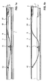
- a sealing strip with a support rail 2 and attached thereto, not shown here sealing profile is lowered and raised.
- a leaf spring 6 is connected to the pressure rod 5 with a first end 60. In the middle Area 61 it is fixed to the support rail 2 and with a second end 62 pivotally mounted on the guide rail 1. Further springs can then be arranged on this first leaf spring 6 and fastened in the same way. As a result, the sealing device can be actuated on one side when opening and closing the door.
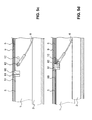
- FIG. 1a the door seal is shown in the open state of the door.
- FIG. 1b it is shown in the closed state of the door.
- the actuating button 4 ' is pressed against a door frame, not shown, so that the actuating rod 40' and the push rod 5 were pressed into the guide rail.
- the prestressed leaf springs 6 were pressed down and lowered the sealing strip.
- the lowerable sealing device has a guide profile rail, a lowerable and liftable spring-loaded sealing strip held therein, and at least one, preferably exactly one, triggering element for raising and lowering the sealing strip.
- the sealing strip is raised in a basic position of the trigger element and lowered in a first triggering position of the trigger element.
- the triggering element has a second triggering position, which is different from the first, wherein the sealing strip is also lowered in this second triggering position.
- the movement of the trigger element is parallel to the longitudinal axis of the guide rail, i. the trigger element is moved.
- it is also possible for it to be panned or to perform another movement.
- the basic position is preferably located between the first and second triggering positions, in particular centrally therewith. However, it is also possible for the first and second triggering positions to lie on the same side of the basic position, one of which is further away from the basic position than the other.
- the sealing device preferably has a guide profile rail and a lowerable and liftable sealing strip held therein.
- the sealing strip is spring-loaded and can be lowered by displacing a triggering element from a basic position in a first direction. It can also be lowered by displacement of the triggering element in a second direction opposite the first direction, wherein the sealing strip is raised when the actuating rod passes through the basic position.
- the sealing device is lowered automatically either by train or by pressure on the actuating rod.
- the release mechanism only one of these two possible strokes or both strokes can be used.
- both strokes the seal is activated at two different positions of the trigger mechanism.
- the seal can only be triggered by pulling on a power transmission rod.
- the sealing device comprises a guide rail, a held in the guide rail, lowerable and liftable sealing strip, a first power transmission rod, which extends in the longitudinal direction of the guide rail and is slidably held in this in its longitudinal direction, at least one spring comprising lowering element, which is arranged in the guide rail, which is connected to the sealing strip and which can be actuated by means of the first power transmission rod for the purpose of lowering the sealing strip.
- the lowering element has a position which is held displaceably in relation to the guide profile rail in this.
- the first power transmission rod is connected to a driver which entrains this point of the Absenkelements in longitudinal displacement of the first power transmission rod in a first direction and does not take along with longitudinal displacement of the first power transmission rod in a second, opposite direction, this displaceable position of the Absenkelements.
- the lowering element may consist exclusively of a lowering spring, in particular a leaf spring. However, it may also be, for example, a combination of rods, slides and springs, such as coil springs.
- the lowerable sealing device preferably comprises a guide profile rail, a lowerable and liftable sealing strip held in the guide profile rail, a first force transmission rod which extends in the longitudinal direction of the guide profile rail and is held displaceably in its longitudinal direction, and at least one lowering spring, which is fastened at its ends and which approximate is attached in its center to the sealing strip.
- the at least one Absenkfeder extends between these attachment points inclined to the longitudinal direction of the guide rail and loaded the sealing strip in its raised state.
- the lowering spring is fixed in position at its first end to the guide rail or slidably mounted on a second power transmission rod with respect to the guide rail and the Absenkfeder is slidably attached to the guide rail at its second end in the longitudinal direction of the guide rail.
- the first power transmission rod is connected to a driver, which in longitudinal displacement of the power transmission rod in a first direction entrains the longitudinally displaceable second end of the Absenkfeder and leaves in longitudinal displacement of the power transmission rod in a second, opposite direction, the second end of the Absenkfeder.
- the sealing device comprises a guide profile rail, a lowerable and liftable sealing strip held in the guide profile rail, a force transmission rod which extends in the longitudinal direction of the guide profile rail and is held displaceably in its longitudinal direction, at least one lowering element comprising a spring is connected to the sealing strip and which by means of the power transmission rod for the purpose of lowering the sealing strip is actuated.
- the guide rail has a window for connecting an operating rod to the power transmission rod, wherein the window is arranged so that the connection is made in an approximately perpendicular direction to the longitudinal direction of the guide rail.
- Absenkelement can consist exclusively of a leaf spring.
- the lowerable sealing device preferably comprises a guide profile rail, a lowerable and held in the guide rail Liftable sealing strip, a power transmission rod, which extends in the longitudinal direction of the guide rail and is held displaceably in this in its longitudinal direction, and at least one Absenkfeder, which is connected to the guide rail, the sealing strip and the power transmission rod or operatively connected.
- This Absenkfeder extends between these attachment points inclined to the longitudinal direction of the guide rail and loaded the sealing strip in its raised state.
- the guide rail has a window for connecting an operating rod to the power transmission rod, wherein the window is arranged so that the connection takes place in an approximately perpendicular direction to the longitudinal direction of the guide rail.
- the triggering of the lowering mechanism is thus not the end face at the end or outside the guide rail but within its length.
- the location of the trigger may be adjacent to an end. However, it may also be in the middle or another area along the length of the guide rail.
- this arrangement can be used for pure Switzerlandausaten, pure pressure releases or combinations thereof.
- the threshold of the door or the window should in particular be a maximum of 20 mm and thus be handicapped accessible.
- the inventive door or the window according to the invention has a frame, at least one door or window sash and a locking mechanism which locks at least below in the region of the threshold.
- the frame has thermally separated profiles.
- the door or the window has a lowerable when closing or opening the door or window sash or Liftable sealing device.
- the associated frame area can be made relatively low and thus suitable for the disabled. It still protects reliably even against driving rain.
- sealing devices can be used known mechanically and automatically lowerable seals.
- the normal window lever can be used to actuate the sealing device. This means that when opening and closing the window or the door of this lever, the sealing strip raises or lowers.
- the seal can be lowered not only when the window or door is closed, but also in a second closure position, in particular when the window or tilted door is tilted.
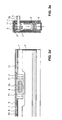
- FIGS. 2a to 2e a first embodiment of an inventive lowering seal is shown, which is automatically triggered.
- the sealing device is not visible in its entire length. Furthermore, only a single Absenkfeder is shown. However, the device usually has a plurality, preferably two Absenkfedern, which are arranged one behind the other in the longitudinal direction of the seal.
- FIG. 2a is shown a side view of the sealing device, wherein the parts located in the interior of the housing are shown with thinner lines.
- the housing is formed by a U-shaped, downwardly open guide rail 1, which has two parallel side walls and an upper web. It is usually made of aluminum.
- guide rail 1 In the interior of the guide rail 1 is an in FIG. 2a Not shown sealing strip held raised and lowered.
- the sealing strip includes, as in the Figures 2c and 2e is best seen, a rigid support rail 2, preferably made of aluminum, and a thereto attached elastomeric sealing profile 3, which in FIG. 2e is shown.
- the guide profile rail 1 has a passage opening or a window 10.
- This window 10 may be arranged in a side wall in an end region of the rail 1 and located adjacent to the upper web. However, it may also be arranged, for example, in the middle region of the rail, also preferably in the region of the upper web, or at another suitable location. Preferably, only one window 10 is present. However, it is also possible, for example, to arrange several windows on the same, on opposite sides and / or in the upper web. The windows can vary depending on the application, but they do not have to be aligned with each other.
- the window 10 is rectangular in shape, extending with its longitudinal direction in the longitudinal direction of the guide rail 1. Other shapes are also possible.
- At least one Absenkfeder In the interior of the guide rail 1 is at least one Absenkfeder, preferably two Absenkfedern are arranged. They are preferably designed as flat leaf springs 6, which extend in the longitudinal direction of the guide rail 1. These lowering springs are often referred to as bending springs.
- a power transmission rod 5 is arranged in a groove 11 formed by the upper web and two projecting ribs or noses of the guide rail (see FIG. 2e ).
- This example is a push rod as known in the art. It preferably has a rectangular cross section and is formed flat. It extends approximately over the entire length of the guide rail 1, wherein it may be one or more pieces.
- This power transmission rod 5 is often referred to as a basic spring.
- each leaf spring 6 is now attached to a first end 60 on the push rod 5, here by means of a screw or a rivet.
- each leaf spring 6 is attached to the sealing strip, more precisely to the carrier profile rail 2. This is done here by means of a plastic part, which is einklippsbar on both sides in the carrier rail 2 and which has a passage opening for the leaf spring 6. It is the Leaf spring 6 is preferably held immovably therein. With its second end 62, the leaf spring 6 is fixed to the guide rail 1, wherein it is held in a plastic part, which is pivotally mounted in the guide rail 1.
- One end of the push rod 5 is connected to a triggering element or trip block 7, which projects away from the push rod 5 down into the cavity of the guide rail 1.
- a triggering element or trip block 7 which projects away from the push rod 5 down into the cavity of the guide rail 1.
- it is screwed to the push rod 5 by means of screws 71, as shown in FIG Figure 2d is recognizable.
- Other types of fastening are possible.
- the trip block 7 is located in the region of the window 10 and behind this. This is according to FIG. 2a adjacent to the region where the first end 60 of the leaf spring 6 is attached to the push rod 5.
- This block 7 is preferably made of plastic. However, it can also consist of another material, in particular metal.
- the trip block 7 preferably has a cuboid basic shape. It is provided with a receiving opening 70 which is directed towards the window 10 of the guide rail 1, so that access to the opening 70 is ensured by the window 10.
- the receiving opening 70 preferably has an oval shape. It may alternatively have other shapes.
- this receiving opening 70 can be an end of an operating rod 4 introduce. This is in FIG. 2e recognizable.
- the rod can be straight or angled.
- the bar 4 is hatched.
- the receiving opening 70 is larger than the diameter of the rod 4. This facilitates the insertion of the rod 4 in the opening 70 of the mounted device.
- the opening 70 at least in the longitudinal direction of the guide rail 1 is greater than the corresponding dimension of the rod 4.
- the opening 70 may be fork-shaped, which encloses the end of the actuating lever.
- the second or the further springs can connect on the left side.
- the window 10 and the trip block 7 is disposed between two springs.
- the push rod 5 extends in this case on both sides of the trip block 7, i. this is not attached to one end of the push rod 5, but in its middle or another area.
- the springs 6 are fastened in an analogous manner to the pressure rod. That the spring 6 located on the right side of the trip block 7 is connected to the push rod at its end remote from this block. With its end near this block, it is in turn attached to the guide rail 1 via a hinge. In this case, the spring located on the right side of the trip block 7 is not triggered by pressure but by train. Therefore, in this case, the term power transmission rod is better used instead of compression rod.
- the window 10 can also be arranged on both opposite sides of the guide profile rail so that the release block is accessible on both sides. This may cause the same actuation of the seal either either individually or jointly triggered by both sides.
- the first case makes it possible to use the same type of seal for left and right casements. When released together and at the same time, power transmission is improved. However, if triggered on both sides with a time delay, then a first lowering from one side and a second lowering from another side can be achieved by different triggering means or different movements of the same triggering means. The same applies if several windows are arranged on the same side of the seal or in the upper web. This significantly increases the flexibility in the application of the seal.
- the window 10 may be arranged in the upper web of the guide rail 1, so that the release is not laterally but from above.
- each spring 6 is fixed with a first end 60 on the push rod 5. With its central end 61, it is firmly connected to the carrier rail 2. Its second end 62 is in turn pivotally held in the guide rail 1. In addition, however, this second end 62 is held displaceably in the longitudinal direction of the guide rail 1.
- the rail 1 in each side walls each have a slot 12 which are opposed to each other and which extend in the longitudinal direction of the guide rail 1.
- a second power transmission rod is present, which is here called tension rod 9. It is preferably the same design as the push rod 5, ie with a rectangular cross-section and flat. Preferably, it runs parallel and above the push rod 5. However, it can also extend below or laterally thereto. An arrangement of the two rods 5, 9 one above the other has the advantage that the sealing device can still be made very narrow.
- the guide profile rail 1 for this purpose preferably has two grooves 11 ', 11 "arranged one below the other and adjacent to the upper web, which are formed on both sides by inwardly projecting longitudinal ribs of the side walls The pressure rod 5 is also held displaceably in the longitudinal direction in the lower groove 11 ".
- both bars 5, 9 are preferably made of metal, in particular steel.
- trigger element or a trip block 7 is present, which is arranged in the region of the window 10 of the guide rail 1.
- this trip block 7 is now not attached to the compression spring 5, but to the tension spring 9. This can in turn be done by means of screws 71 or other types of fastening.
- the trip block 7 in turn has at least one receiving opening 70, in which an actuating rod 4 can be inserted to move the trip block 7 within the permitted range through the window 10 to the right or to the left and so the pull rod 9 within the guide rail 1 move.
- the trip block 7 passes through the push rod 5.
- the push rod 5 has a first passage opening 50, which is designed to be longer in the longitudinal direction of the guide profile rail 1 than the trigger block 7.
- a stop 8 is present. This is attached to the inside of the web of the guide rail 1, in particular screwed.
- it is a block-shaped block. It can be made of metal, plastic or other suitable material.
- the stopper 8 protrudes sufficiently deep down to stop the movement of the push rod 5 in the direction to the right, ie from the trip block 7, away.
- a driver 91 is fixed in position on the pull rod 9 fastened, preferably by means of a screw 90.
- This driver may also be formed as a substantially block-shaped block made of plastic or metal. Other shapes are also possible. Preferably, it has a part-spherical recess 92 towards the leaf spring 6, which corresponds to the outer contour of the rotary joint of the second end 62 of the leaf spring 6.
- the push rod 5 has in this area a second passage opening 51, which is penetrated by the driver 91.
- the second passage opening 51 is formed longer in the longitudinal direction of the guide rail 1 than the driver 91.
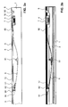
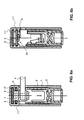
- FIG. 3a It can be seen that the actuating rod 4 in turn engages laterally within the length of the guide rail 1 through the window 10 in the lowering mechanism and this actuated by displacement of the trip block 7 to the right or to the left.
- FIG. 4a shows that the trip block 7 passes through the push rod 5 ineffective.
- FIG. 5a shows that in this position, the driver spaced from the second end 62 of the leaf spring 6 is arranged and this second end 62 is located on the left, the trip block 7 far end of the slot 12.
- FIG. 3b is the sealing strip or the carrier rail 2 in its rest position and is raised.
- the spring 6 is preloaded and slightly bent, but exerts no force on the support rail 2 from.
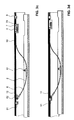
- the in the FIGS. 4b and 5b illustrated situations correspond to those already above based on the FIGS. 4a and 5a described.
- the second end 62 which at the left end of the slot 12 already is pending, was pivoted as in the above example and the central portion 61 of the spring 6 has been lowered. With him also lowered the sealing strip 2, 3, which can now rest on the ground sealing. The pull rod 9 was indeed moved to the left. However, with him also moved the driver 91, which was even more remote from the second end 62 of the leaf spring 6. As a result, the movement of the tension rod 9 had no influence on the leaf spring 6, as in FIG. 5c is shown.
- the driver 91 can now push the second end 62 of the spring 6 further forward without the entire spring 6 also being displaced.
- the spring 6 is stretched again, the central region 61 lowers and the sealing strip 2, 3 is lowered again sealingly on the ground.
- the first and second passage openings 50, 51 must be large enough to allow these movements without affecting the pressure rod 5. In addition, they must be short enough to be as stop or effective surfaces for the driver 91 and the stop block 7 to serve so that they can be taken after a certain free displacement of these parts 91, 7 of them.
- This arrangement thus enables a double stroke. That is, a lowering of the sealing strip takes place when moving from a central position both to the right and to the left.
- the window 10 and thus the engagement of the actuating rod 4 from the outside both on one side via a side wall of the guide rail 1, be arranged on both sides on both side walls and / or from above the upper web of the guide rail 1 or done.
- the double stroke can be triggered by the same window or by two different windows.
- the window 10 can in turn be arranged in the region of an end face of the rail. If there are several, in particular two, springs, these are arranged in succession on one side of the window in the abovementioned case.
- the window 10 may also be arranged here in the longitudinal direction of the rail 1 in the middle or in another suitable region of the guide rail 1.
- a first spring on the left and a second spring on the right side of the window and thus the trip block is arranged. They are arranged the same aligned one behind the other, that is, the second displaceable end of the second spring is adjacent to the trip block and the first end attached to the push rod is located in the trigger block remote area of the guide rail.
- the push rod 5 acts on this second spring as a tie rod and the tension rod 9 as a push rod.
- the operative connection between the first power transmission rod 9 and lowering spring 6 always via a driver and the operative connection between the second power transmission rod 5 and lowering spring 6 via a fixed connection, in particular by means of a Screw or a rivet.
- the triggering of the lowering mechanism does not necessarily have to be within the length of the guide rail 1 lie. The triggering can also be done on the front side.
- the trip block or the drive element can be provided with an eyelet into which the counterpart engages accordingly.
- this arrangement can also be provided only with the pull rod 9, so that only one stroke is made possible by pulling.
- the sealing devices are the same except for the inventive lowering mechanisms as in EP 0 338 974 .
- the sealing profile is also integrally formed here and mounted on two opposite sides or centrally on the support rail, so that a lower arc is formed, which can rest on the floor sealing.
- the legs of the sealing profile, which extend above the attachment point, are each on one side of the guide rail sealingly to this.
- the inventive teaching is not only applicable to such sealing devices, but is also suitable for other types of seals, in particular other types of sealing profiles and lowering mechanisms.
- the inventive teaching can also be applied to lowering mechanisms, such as those in DE 35 26 720 .
- DE 34 18 438 and DE 34 27 938 are disclosed.
- the operating lever may be a separate lever, which is used only for actuating the lowering seal.
- it is a lever which is also used to operate the door leaf or window or for a locking system coupled thereto. He may also be mechanically coupled with such a lever.
- the triggering is thus no longer mandatory by queuing a trigger button on a door frame but by an active movement of a lever, which is triggered manually or by motor.
- the sealing device according to the invention is suitable not only for use in threshold-free doors but also for balcony doors or windows, in particular for lift-and-slide doors.
- the actuating lever 4 in particular in this case, the actuating lever, which allows opening, closing, locking and tilting of the door or the window sash.
- the described guide rail 1 may be a separate part which is fixed in a corresponding groove of the door or window sash. But it can already be molded in the door or window sash and therefore be an integral part of the door or window profile. This is especially possible with metal and plastic windows.
- the automatic lowering seals described above are used in a door or window having a lockable door or window sash and a frame comprising thermally separated profiles.
- the locking takes place in the lower horizontal area of the door or the window, either to tilt them or be it to ensure increased tightness or security against burglary.
- the lowering seal is preferably arranged in the door leaf or window sash.
- the profile region of the frame below the Absenkdichtung can be relatively low, in particular 20 mm maximum formed.
- balcony doors or sliding doors can be adapted for the disabled with barely perceptible thresholds, without the tightness of the door or the window is reduced or the possibility of locking in the lower region or the thermal separation of the profiles is impaired.
- a seal which allows a double stroke, so the seal can be lowered not only when closing or locking the window or the door, but also when the door or the window is tilted.
- the lever of the window is brought into a first position to lock the window. At the same time he lowers the seal.
- a second position of the lever opens the window. He lifts the seal.
- a third position is used to tilt the window. He lowers the seal again. This allows a tilted window or a Door in the lower area still to seal, especially against driving rain, without a separate mechanism must be installed.
- the inventive sealing device increases the flexibility in its application by the different types of triggering.
Landscapes
- Engineering & Computer Science (AREA)
- Civil Engineering (AREA)
- Structural Engineering (AREA)
- Specific Sealing Or Ventilating Devices For Doors And Windows (AREA)
- Sealing Devices (AREA)
Priority Applications (1)
| Application Number | Priority Date | Filing Date | Title |
|---|---|---|---|
| EP16203622.2A EP3165703B1 (fr) | 2008-02-04 | 2009-01-30 | Dispositif d'étanchéité abaissable |
Applications Claiming Priority (1)
| Application Number | Priority Date | Filing Date | Title |
|---|---|---|---|
| CH1532008 | 2008-02-04 |
Related Child Applications (1)
| Application Number | Title | Priority Date | Filing Date |
|---|---|---|---|
| EP16203622.2A Division EP3165703B1 (fr) | 2008-02-04 | 2009-01-30 | Dispositif d'étanchéité abaissable |
Publications (3)
| Publication Number | Publication Date |
|---|---|
| EP2085559A2 true EP2085559A2 (fr) | 2009-08-05 |
| EP2085559A3 EP2085559A3 (fr) | 2014-09-10 |
| EP2085559B1 EP2085559B1 (fr) | 2016-12-14 |
Family
ID=40600266
Family Applications (2)
| Application Number | Title | Priority Date | Filing Date |
|---|---|---|---|
| EP09405019.2A Active EP2085559B1 (fr) | 2008-02-04 | 2009-01-30 | Dispositif d'étanchéité abaissable |
| EP16203622.2A Active EP3165703B1 (fr) | 2008-02-04 | 2009-01-30 | Dispositif d'étanchéité abaissable |
Family Applications After (1)
| Application Number | Title | Priority Date | Filing Date |
|---|---|---|---|
| EP16203622.2A Active EP3165703B1 (fr) | 2008-02-04 | 2009-01-30 | Dispositif d'étanchéité abaissable |
Country Status (2)
| Country | Link |
|---|---|
| EP (2) | EP2085559B1 (fr) |
| RU (1) | RU2009103202A (fr) |
Cited By (16)
| Publication number | Priority date | Publication date | Assignee | Title |
|---|---|---|---|---|
| DE202012100752U1 (de) | 2012-03-02 | 2013-06-04 | Athmer Ohg | Dichtung, insbesondere Schiebetürdichtung |
| EP2682556A1 (fr) | 2012-07-02 | 2014-01-08 | Planet GDZ AG | Dispositif dýétanchéité pour une porte ou une fenêtre |
| WO2014019955A1 (fr) * | 2012-07-30 | 2014-02-06 | Planet Gdz Ag | Garniture d'étanchéité abaissable et partie de bâtiment |
| CN105275317A (zh) * | 2015-11-30 | 2016-01-27 | 南京二十六度建筑节能工程有限公司 | 一种塑钢外遮阳一体化窗及其制造方法 |
| WO2016066576A1 (fr) | 2014-10-27 | 2016-05-06 | Planet Gdz Ag | Dispositif d'étanchéité |
| EP3085876A1 (fr) | 2015-04-20 | 2016-10-26 | Planet GDZ AG | Dispositif de joint descendant et unité de déclenchement |
| EP3203006A1 (fr) * | 2016-02-02 | 2017-08-09 | Athmer oHG | Profil d'etancheite d'une porte |
| CN107130900A (zh) * | 2017-06-09 | 2017-09-05 | 天津市佐佳奇装饰材料制造有限公司 | 一种响应灵敏的门底密封装置 |
| WO2017190779A1 (fr) | 2016-05-04 | 2017-11-09 | Planet Gdz Ag | Dispositif d'étanchéité |
| WO2017191273A1 (fr) | 2016-05-04 | 2017-11-09 | Planet Gdz Ag | Dispositif d'étanchéification pour une porte coulissante |
| DE202018101839U1 (de) | 2017-12-19 | 2018-04-24 | Planet Gdz Ag | Türflügel mit Dichtungssystem |
| EP3396099A1 (fr) | 2017-04-27 | 2018-10-31 | Walter Degelsegger | Dispositif de joint d'étanchéité |
| EP3211170B1 (fr) | 2016-02-23 | 2019-09-25 | Sunflex Aluminiumsysteme GmbH | Systeme de vantail coulissant avec dispositif d'étanchéité abaissable |
| WO2019179937A1 (fr) * | 2018-03-19 | 2019-09-26 | Planet Gdz Ag | Dispositif d'étanchéité |
| EP3767060A1 (fr) * | 2019-07-18 | 2021-01-20 | Athmer OHG | Procédé de surveillance d'une ferrure de porte ou d'une porte, ferrure de porte, en particulier joint d'étanchéité, poussoir ou charnière, dotée d'un capteur et porte dotée d'un capteur ou d'une telle ferrure de porte dotée d'un capteur |
| EP4653659A1 (fr) | 2024-05-22 | 2025-11-26 | ASSA ABLOY (Schweiz) AG | Ensemble pour un battant de porte ou de fenêtre |
Families Citing this family (1)
| Publication number | Priority date | Publication date | Assignee | Title |
|---|---|---|---|---|
| DE202022102658U1 (de) * | 2022-05-13 | 2022-05-30 | Athmer Ohg | Dichtung, insbesondere für Schiebetüren oder Schiebetore |
Citations (6)
| Publication number | Priority date | Publication date | Assignee | Title |
|---|---|---|---|---|
| DE3427938A1 (de) | 1984-02-28 | 1985-09-12 | Fa. F. Athmer, 5760 Arnsberg | Automatische dichtungsvorrichtung fuer einen unteren tuerspalt |
| DE3418438A1 (de) | 1984-05-18 | 1985-11-21 | Fa. F. Athmer, 5760 Arnsberg | Tuerdichtungsvorrichtung |
| DE3526720A1 (de) | 1984-07-28 | 1986-01-30 | Fa. F. Athmer, 5760 Arnsberg | Dichtungsvorrichtung fuer den unteren tuerspalt eines tuerfluegels |
| EP0338974A2 (fr) | 1988-04-19 | 1989-10-25 | " Planet" Matthias Jaggi | Dispositif d'étanchéité pour portes sans seuil |
| EP0509961A1 (fr) | 1991-04-17 | 1992-10-21 | Planet MJT AG | Dispositif d'étanchéité, particulièrement pour battants de portes |
| DE19516530A1 (de) | 1994-06-01 | 1995-12-07 | Matthias Jaggi | Dichtungsvorrichtung, insbesondere für Türflügel |
Family Cites Families (7)
| Publication number | Priority date | Publication date | Assignee | Title |
|---|---|---|---|---|
| DE3124106A1 (de) * | 1981-06-19 | 1982-12-30 | Fa. F. Athmer, 5760 Arnsberg | "abdichtungsvorrichtung fuer tueren" |
| DE9004118U1 (de) * | 1990-04-09 | 1990-06-28 | Roto Frank AG, 7022 Leinfelden-Echterdingen | Dichteinrichtung für einen Flügel eines Fensters, einer Tür od.dgl. |
| DE4304155C2 (de) | 1993-02-12 | 1997-04-03 | Hahn Gmbh & Co Kg Dr | Automatische Bodendichtung für eine Tür |
| JPH1193541A (ja) | 1997-09-24 | 1999-04-06 | Shibutani:Kk | 引き戸のシール装置 |
| DE29720978U1 (de) * | 1997-11-26 | 1998-03-12 | Ernst Keller GmbH & Co KG, 59757 Arnsberg | Vorrichtung zum Arretieren von Türen in beliebigen Schwenkwinkeln |
| DE19933576A1 (de) * | 1999-07-22 | 2001-01-25 | Siegenia Frank Kg | Beschlag für Fenster oder Türen |
| US20040010973A1 (en) | 2002-07-22 | 2004-01-22 | Tk Canada Limited | Automatic door sweep |
-
2009
- 2009-01-30 EP EP09405019.2A patent/EP2085559B1/fr active Active
- 2009-01-30 EP EP16203622.2A patent/EP3165703B1/fr active Active
- 2009-02-02 RU RU2009103202/03A patent/RU2009103202A/ru not_active Application Discontinuation
Patent Citations (6)
| Publication number | Priority date | Publication date | Assignee | Title |
|---|---|---|---|---|
| DE3427938A1 (de) | 1984-02-28 | 1985-09-12 | Fa. F. Athmer, 5760 Arnsberg | Automatische dichtungsvorrichtung fuer einen unteren tuerspalt |
| DE3418438A1 (de) | 1984-05-18 | 1985-11-21 | Fa. F. Athmer, 5760 Arnsberg | Tuerdichtungsvorrichtung |
| DE3526720A1 (de) | 1984-07-28 | 1986-01-30 | Fa. F. Athmer, 5760 Arnsberg | Dichtungsvorrichtung fuer den unteren tuerspalt eines tuerfluegels |
| EP0338974A2 (fr) | 1988-04-19 | 1989-10-25 | " Planet" Matthias Jaggi | Dispositif d'étanchéité pour portes sans seuil |
| EP0509961A1 (fr) | 1991-04-17 | 1992-10-21 | Planet MJT AG | Dispositif d'étanchéité, particulièrement pour battants de portes |
| DE19516530A1 (de) | 1994-06-01 | 1995-12-07 | Matthias Jaggi | Dichtungsvorrichtung, insbesondere für Türflügel |
Cited By (35)
| Publication number | Priority date | Publication date | Assignee | Title |
|---|---|---|---|---|
| EP2634350A2 (fr) | 2012-03-02 | 2013-09-04 | Athmer oHG | Joint amovible, notamment joint de porte coulissante |
| EP2634350A3 (fr) * | 2012-03-02 | 2015-05-13 | Athmer oHG | Joint amovible, notamment joint de porte coulissante |
| DE202012100752U1 (de) | 2012-03-02 | 2013-06-04 | Athmer Ohg | Dichtung, insbesondere Schiebetürdichtung |
| EP2682556A1 (fr) | 2012-07-02 | 2014-01-08 | Planet GDZ AG | Dispositif dýétanchéité pour une porte ou une fenêtre |
| US9803418B2 (en) | 2012-07-30 | 2017-10-31 | Planet Gdz Ag | Drop-down seal and building part |
| WO2014019955A1 (fr) * | 2012-07-30 | 2014-02-06 | Planet Gdz Ag | Garniture d'étanchéité abaissable et partie de bâtiment |
| US20150211288A1 (en) * | 2012-07-30 | 2015-07-30 | Planet Gdz Ag | Drop-down seal and building part |
| JP2015527511A (ja) * | 2012-07-30 | 2015-09-17 | プラネット ゲーデーツェット アーゲー | ドロップダウンシール及び建物部分 |
| EP2888428B2 (fr) † | 2012-07-30 | 2026-03-18 | ASSA ABLOY (Schweiz) AG | Joint descendant et élément de construction |
| EP2888428B1 (fr) | 2012-07-30 | 2021-08-25 | ASSA ABLOY (Schweiz) AG | Joint descendant et élément de construction |
| AU2013298688B2 (en) * | 2012-07-30 | 2016-08-11 | Planet Gdz Ag | Drop-down seal and building part |
| WO2016066576A1 (fr) | 2014-10-27 | 2016-05-06 | Planet Gdz Ag | Dispositif d'étanchéité |
| AU2015340758B2 (en) * | 2014-10-27 | 2018-12-06 | Planet Gdz Ag | Sealing device |
| CN107075900A (zh) * | 2014-10-27 | 2017-08-18 | 普兰特Gdz股份公司 | 密封设备 |
| WO2016066577A3 (fr) * | 2014-10-27 | 2016-08-04 | Planet Gdz Ag | Dispositif d'étanchéité |
| CN107002457A (zh) * | 2014-10-27 | 2017-08-01 | 普兰特Gdz股份公司 | 密封设备 |
| JP2017535699A (ja) * | 2014-10-27 | 2017-11-30 | プラネット ゲーデーツェット アーゲー | シーリング装置 |
| AU2015340757B2 (en) * | 2014-10-27 | 2018-12-13 | Planet Gdz Ag | Sealing device |
| EP3085876A1 (fr) | 2015-04-20 | 2016-10-26 | Planet GDZ AG | Dispositif de joint descendant et unité de déclenchement |
| CN105275317A (zh) * | 2015-11-30 | 2016-01-27 | 南京二十六度建筑节能工程有限公司 | 一种塑钢外遮阳一体化窗及其制造方法 |
| EP3203006A1 (fr) * | 2016-02-02 | 2017-08-09 | Athmer oHG | Profil d'etancheite d'une porte |
| EP3203006B1 (fr) | 2016-02-02 | 2019-09-04 | Athmer oHG | Profil d'etancheite d'une porte |
| EP3211170B1 (fr) | 2016-02-23 | 2019-09-25 | Sunflex Aluminiumsysteme GmbH | Systeme de vantail coulissant avec dispositif d'étanchéité abaissable |
| WO2017191273A1 (fr) | 2016-05-04 | 2017-11-09 | Planet Gdz Ag | Dispositif d'étanchéification pour une porte coulissante |
| WO2017190779A1 (fr) | 2016-05-04 | 2017-11-09 | Planet Gdz Ag | Dispositif d'étanchéité |
| US11118395B2 (en) | 2016-05-04 | 2021-09-14 | Assa Abloy (Schweiz) Ag | Sealing device |
| EP3396099A1 (fr) | 2017-04-27 | 2018-10-31 | Walter Degelsegger | Dispositif de joint d'étanchéité |
| CN107130900A (zh) * | 2017-06-09 | 2017-09-05 | 天津市佐佳奇装饰材料制造有限公司 | 一种响应灵敏的门底密封装置 |
| EP3502406A1 (fr) | 2017-12-19 | 2019-06-26 | Planet GDZ AG | Vantail de porte doté d'un système d'étanchéité |
| WO2019120970A1 (fr) | 2017-12-19 | 2019-06-27 | Planet Gdz Ag | Battant de porte comprenant un système d'étanchéité |
| DE202018101839U1 (de) | 2017-12-19 | 2018-04-24 | Planet Gdz Ag | Türflügel mit Dichtungssystem |
| WO2019179937A1 (fr) * | 2018-03-19 | 2019-09-26 | Planet Gdz Ag | Dispositif d'étanchéité |
| EP4212694A1 (fr) * | 2018-03-19 | 2023-07-19 | ASSA ABLOY (Schweiz) AG | Dispositif d'étanchéité |
| EP3767060A1 (fr) * | 2019-07-18 | 2021-01-20 | Athmer OHG | Procédé de surveillance d'une ferrure de porte ou d'une porte, ferrure de porte, en particulier joint d'étanchéité, poussoir ou charnière, dotée d'un capteur et porte dotée d'un capteur ou d'une telle ferrure de porte dotée d'un capteur |
| EP4653659A1 (fr) | 2024-05-22 | 2025-11-26 | ASSA ABLOY (Schweiz) AG | Ensemble pour un battant de porte ou de fenêtre |
Also Published As
| Publication number | Publication date |
|---|---|
| EP3165703A2 (fr) | 2017-05-10 |
| RU2009103202A (ru) | 2010-08-10 |
| EP2085559B1 (fr) | 2016-12-14 |
| EP3165703A3 (fr) | 2017-07-05 |
| EP2085559A3 (fr) | 2014-09-10 |
| EP3165703B1 (fr) | 2021-05-19 |
Similar Documents
| Publication | Publication Date | Title |
|---|---|---|
| EP2085559B1 (fr) | Dispositif d'étanchéité abaissable | |
| EP2474698B1 (fr) | Dispositif d'étanchéité doté d'un profil d'étanchéité et d'un mécanisme destiné au déplacement du profil d'étanchéité lors de l'actionnement du mécanisme | |
| EP2888428B1 (fr) | Joint descendant et élément de construction | |
| EP2860333B1 (fr) | Agencement de fermeture pour la fermeture de deux battants coulissants | |
| EP3417134B1 (fr) | Ensemble ferrure pour le raccordement d'un battant coulissant et basculant | |
| EP0178610A2 (fr) | Serrure | |
| EP3112577B1 (fr) | Joint abaissable | |
| EP3752700B1 (fr) | Protection anti-effraction abaissable | |
| DE202016101097U1 (de) | Verriegelungseinrichtung und dazugehörige Schiebetüranlage | |
| EP2050918A2 (fr) | Joint descendant doté d'une ouverture de passage | |
| EP1008713B1 (fr) | Dispositif de verrouillage | |
| EP1264954B1 (fr) | Système de verouillage | |
| DE3112310C2 (de) | Lüftungsvorrichtung | |
| EP0945579A2 (fr) | Dispositif de ventilation | |
| EP3085876B1 (fr) | Dispositif de joint descendant | |
| EP2682556B1 (fr) | Dispositif d'étanchéité pour une porte ou une fenêtre | |
| DE202004007565U1 (de) | Bodendichtung mit Federband | |
| EP2787160B1 (fr) | Joint de verrou et système de joint doté de celui-ci | |
| EP2685040B1 (fr) | Composant précontraint et procédé de fonctionnement pour une fenêtre ou une porte-fenêtre | |
| DE102012202151A1 (de) | Treibstangenbeschlag mit Spaltlüftungs- und Verriegelungsfunktion | |
| DE202004005162U1 (de) | Bodendichtung mit Federband | |
| EP4212694B1 (fr) | Dispositif d'étanchéité | |
| WO2019015939A1 (fr) | Joint d'étanchéité à abaissement | |
| EP4653659A1 (fr) | Ensemble pour un battant de porte ou de fenêtre | |
| DE102004062763A1 (de) | Schließfolgeregelung |
Legal Events
| Date | Code | Title | Description |
|---|---|---|---|
| PUAI | Public reference made under article 153(3) epc to a published international application that has entered the european phase |
Free format text: ORIGINAL CODE: 0009012 |
|
| AK | Designated contracting states |
Kind code of ref document: A2 Designated state(s): AT BE BG CH CY CZ DE DK EE ES FI FR GB GR HR HU IE IS IT LI LT LU LV MC MK MT NL NO PL PT RO SE SI SK TR |
|
| AX | Request for extension of the european patent |
Extension state: AL BA RS |
|
| RIN1 | Information on inventor provided before grant (corrected) |
Inventor name: DINTHEER, ANDREAS |
|
| PUAL | Search report despatched |
Free format text: ORIGINAL CODE: 0009013 |
|
| AK | Designated contracting states |
Kind code of ref document: A3 Designated state(s): AT BE BG CH CY CZ DE DK EE ES FI FR GB GR HR HU IE IS IT LI LT LU LV MC MK MT NL NO PL PT RO SE SI SK TR |
|
| AX | Request for extension of the european patent |
Extension state: AL BA RS |
|
| RIC1 | Information provided on ipc code assigned before grant |
Ipc: E06B 7/215 20060101AFI20140221BHEP |
|
| PUAF | Information related to the publication of a search report (a3 document) modified or deleted |
Free format text: ORIGINAL CODE: 0009199SEPU |
|
| D17D | Deferred search report published (deleted) | ||
| RIC1 | Information provided on ipc code assigned before grant |
Ipc: E06B 7/215 20060101AFI20140502BHEP |
|
| RAP1 | Party data changed (applicant data changed or rights of an application transferred) |
Owner name: PLANET GDZ AG |
|
| PUAL | Search report despatched |
Free format text: ORIGINAL CODE: 0009013 |
|
| AK | Designated contracting states |
Kind code of ref document: A3 Designated state(s): AT BE BG CH CY CZ DE DK EE ES FI FR GB GR HR HU IE IS IT LI LT LU LV MC MK MT NL NO PL PT RO SE SI SK TR |
|
| AX | Request for extension of the european patent |
Extension state: AL BA RS |
|
| RIC1 | Information provided on ipc code assigned before grant |
Ipc: E06B 7/215 20060101AFI20140806BHEP |
|
| 17P | Request for examination filed |
Effective date: 20150309 |
|
| RBV | Designated contracting states (corrected) |
Designated state(s): AT BE BG CH CY CZ DE DK EE ES FI FR GB GR HR HU IE IS IT LI LT LU LV MC MK MT NL NO PL PT RO SE SI SK TR |
|
| AKX | Designation fees paid |
Designated state(s): AT BE BG CH CY CZ DE DK EE ES FI FR GB GR HR HU IE IS IT LI LT LU LV MC MK MT NL NO PL PT RO SE SI SK TR |
|
| AXX | Extension fees paid |
Extension state: AL Extension state: RS Extension state: BA |
|
| GRAP | Despatch of communication of intention to grant a patent |
Free format text: ORIGINAL CODE: EPIDOSNIGR1 |
|
| INTG | Intention to grant announced |
Effective date: 20160708 |
|
| STAA | Information on the status of an ep patent application or granted ep patent |
Free format text: STATUS: GRANT OF PATENT IS INTENDED |
|
| GRAS | Grant fee paid |
Free format text: ORIGINAL CODE: EPIDOSNIGR3 |
|
| GRAA | (expected) grant |
Free format text: ORIGINAL CODE: 0009210 |
|
| STAA | Information on the status of an ep patent application or granted ep patent |
Free format text: STATUS: THE PATENT HAS BEEN GRANTED |
|
| AK | Designated contracting states |
Kind code of ref document: B1 Designated state(s): AT BE BG CH CY CZ DE DK EE ES FI FR GB GR HR HU IE IS IT LI LT LU LV MC MK MT NL NO PL PT RO SE SI SK TR |
|
| REG | Reference to a national code |
Ref country code: GB Ref legal event code: FG4D Free format text: NOT ENGLISH |
|
| REG | Reference to a national code |
Ref country code: CH Ref legal event code: EP |
|
| REG | Reference to a national code |
Ref country code: CH Ref legal event code: NV Representative=s name: ISLER AND PEDRAZZINI AG, CH |
|
| REG | Reference to a national code |
Ref country code: IE Ref legal event code: FG4D Free format text: LANGUAGE OF EP DOCUMENT: GERMAN |
|
| REG | Reference to a national code |
Ref country code: AT Ref legal event code: REF Ref document number: 853758 Country of ref document: AT Kind code of ref document: T Effective date: 20170115 |
|
| REG | Reference to a national code |
Ref country code: DE Ref legal event code: R096 Ref document number: 502009013468 Country of ref document: DE Ref country code: FR Ref legal event code: PLFP Year of fee payment: 9 |
|
| PG25 | Lapsed in a contracting state [announced via postgrant information from national office to epo] |
Ref country code: LV Free format text: LAPSE BECAUSE OF FAILURE TO SUBMIT A TRANSLATION OF THE DESCRIPTION OR TO PAY THE FEE WITHIN THE PRESCRIBED TIME-LIMIT Effective date: 20161214 |
|
| REG | Reference to a national code |
Ref country code: NL Ref legal event code: FP |
|
| REG | Reference to a national code |
Ref country code: LT Ref legal event code: MG4D |
|
| PG25 | Lapsed in a contracting state [announced via postgrant information from national office to epo] |
Ref country code: LT Free format text: LAPSE BECAUSE OF FAILURE TO SUBMIT A TRANSLATION OF THE DESCRIPTION OR TO PAY THE FEE WITHIN THE PRESCRIBED TIME-LIMIT Effective date: 20161214 Ref country code: SE Free format text: LAPSE BECAUSE OF FAILURE TO SUBMIT A TRANSLATION OF THE DESCRIPTION OR TO PAY THE FEE WITHIN THE PRESCRIBED TIME-LIMIT Effective date: 20161214 Ref country code: GR Free format text: LAPSE BECAUSE OF FAILURE TO SUBMIT A TRANSLATION OF THE DESCRIPTION OR TO PAY THE FEE WITHIN THE PRESCRIBED TIME-LIMIT Effective date: 20170315 Ref country code: NO Free format text: LAPSE BECAUSE OF FAILURE TO SUBMIT A TRANSLATION OF THE DESCRIPTION OR TO PAY THE FEE WITHIN THE PRESCRIBED TIME-LIMIT Effective date: 20170314 |
|
| PG25 | Lapsed in a contracting state [announced via postgrant information from national office to epo] |
Ref country code: HR Free format text: LAPSE BECAUSE OF FAILURE TO SUBMIT A TRANSLATION OF THE DESCRIPTION OR TO PAY THE FEE WITHIN THE PRESCRIBED TIME-LIMIT Effective date: 20161214 Ref country code: BE Free format text: LAPSE BECAUSE OF NON-PAYMENT OF DUE FEES Effective date: 20170131 Ref country code: FI Free format text: LAPSE BECAUSE OF FAILURE TO SUBMIT A TRANSLATION OF THE DESCRIPTION OR TO PAY THE FEE WITHIN THE PRESCRIBED TIME-LIMIT Effective date: 20161214 |
|
| PG25 | Lapsed in a contracting state [announced via postgrant information from national office to epo] |
Ref country code: IS Free format text: LAPSE BECAUSE OF FAILURE TO SUBMIT A TRANSLATION OF THE DESCRIPTION OR TO PAY THE FEE WITHIN THE PRESCRIBED TIME-LIMIT Effective date: 20170414 Ref country code: SK Free format text: LAPSE BECAUSE OF FAILURE TO SUBMIT A TRANSLATION OF THE DESCRIPTION OR TO PAY THE FEE WITHIN THE PRESCRIBED TIME-LIMIT Effective date: 20161214 Ref country code: CZ Free format text: LAPSE BECAUSE OF FAILURE TO SUBMIT A TRANSLATION OF THE DESCRIPTION OR TO PAY THE FEE WITHIN THE PRESCRIBED TIME-LIMIT Effective date: 20161214 Ref country code: EE Free format text: LAPSE BECAUSE OF FAILURE TO SUBMIT A TRANSLATION OF THE DESCRIPTION OR TO PAY THE FEE WITHIN THE PRESCRIBED TIME-LIMIT Effective date: 20161214 Ref country code: RO Free format text: LAPSE BECAUSE OF FAILURE TO SUBMIT A TRANSLATION OF THE DESCRIPTION OR TO PAY THE FEE WITHIN THE PRESCRIBED TIME-LIMIT Effective date: 20161214 |
|
| PG25 | Lapsed in a contracting state [announced via postgrant information from national office to epo] |
Ref country code: BG Free format text: LAPSE BECAUSE OF FAILURE TO SUBMIT A TRANSLATION OF THE DESCRIPTION OR TO PAY THE FEE WITHIN THE PRESCRIBED TIME-LIMIT Effective date: 20170314 Ref country code: ES Free format text: LAPSE BECAUSE OF FAILURE TO SUBMIT A TRANSLATION OF THE DESCRIPTION OR TO PAY THE FEE WITHIN THE PRESCRIBED TIME-LIMIT Effective date: 20161214 Ref country code: PL Free format text: LAPSE BECAUSE OF FAILURE TO SUBMIT A TRANSLATION OF THE DESCRIPTION OR TO PAY THE FEE WITHIN THE PRESCRIBED TIME-LIMIT Effective date: 20161214 Ref country code: PT Free format text: LAPSE BECAUSE OF FAILURE TO SUBMIT A TRANSLATION OF THE DESCRIPTION OR TO PAY THE FEE WITHIN THE PRESCRIBED TIME-LIMIT Effective date: 20170414 |
|
| REG | Reference to a national code |
Ref country code: DE Ref legal event code: R097 Ref document number: 502009013468 Country of ref document: DE |
|
| PG25 | Lapsed in a contracting state [announced via postgrant information from national office to epo] |
Ref country code: MC Free format text: LAPSE BECAUSE OF FAILURE TO SUBMIT A TRANSLATION OF THE DESCRIPTION OR TO PAY THE FEE WITHIN THE PRESCRIBED TIME-LIMIT Effective date: 20161214 |
|
| PLBE | No opposition filed within time limit |
Free format text: ORIGINAL CODE: 0009261 |
|
| STAA | Information on the status of an ep patent application or granted ep patent |
Free format text: STATUS: NO OPPOSITION FILED WITHIN TIME LIMIT |
|
| REG | Reference to a national code |
Ref country code: IE Ref legal event code: MM4A |
|
| 26N | No opposition filed |
Effective date: 20170915 |
|
| PG25 | Lapsed in a contracting state [announced via postgrant information from national office to epo] |
Ref country code: DK Free format text: LAPSE BECAUSE OF FAILURE TO SUBMIT A TRANSLATION OF THE DESCRIPTION OR TO PAY THE FEE WITHIN THE PRESCRIBED TIME-LIMIT Effective date: 20161214 Ref country code: LU Free format text: LAPSE BECAUSE OF NON-PAYMENT OF DUE FEES Effective date: 20170130 |
|
| REG | Reference to a national code |
Ref country code: FR Ref legal event code: PLFP Year of fee payment: 10 |
|
| REG | Reference to a national code |
Ref country code: BE Ref legal event code: MM Effective date: 20170131 |
|
| PG25 | Lapsed in a contracting state [announced via postgrant information from national office to epo] |
Ref country code: SI Free format text: LAPSE BECAUSE OF FAILURE TO SUBMIT A TRANSLATION OF THE DESCRIPTION OR TO PAY THE FEE WITHIN THE PRESCRIBED TIME-LIMIT Effective date: 20161214 Ref country code: IE Free format text: LAPSE BECAUSE OF NON-PAYMENT OF DUE FEES Effective date: 20170130 |
|
| PG25 | Lapsed in a contracting state [announced via postgrant information from national office to epo] |
Ref country code: MT Free format text: LAPSE BECAUSE OF FAILURE TO SUBMIT A TRANSLATION OF THE DESCRIPTION OR TO PAY THE FEE WITHIN THE PRESCRIBED TIME-LIMIT Effective date: 20161214 |
|
| PG25 | Lapsed in a contracting state [announced via postgrant information from national office to epo] |
Ref country code: HU Free format text: LAPSE BECAUSE OF FAILURE TO SUBMIT A TRANSLATION OF THE DESCRIPTION OR TO PAY THE FEE WITHIN THE PRESCRIBED TIME-LIMIT; INVALID AB INITIO Effective date: 20090130 |
|
| PG25 | Lapsed in a contracting state [announced via postgrant information from national office to epo] |
Ref country code: CY Free format text: LAPSE BECAUSE OF NON-PAYMENT OF DUE FEES Effective date: 20161214 |
|
| PG25 | Lapsed in a contracting state [announced via postgrant information from national office to epo] |
Ref country code: MK Free format text: LAPSE BECAUSE OF FAILURE TO SUBMIT A TRANSLATION OF THE DESCRIPTION OR TO PAY THE FEE WITHIN THE PRESCRIBED TIME-LIMIT Effective date: 20161214 |
|
| PG25 | Lapsed in a contracting state [announced via postgrant information from national office to epo] |
Ref country code: TR Free format text: LAPSE BECAUSE OF FAILURE TO SUBMIT A TRANSLATION OF THE DESCRIPTION OR TO PAY THE FEE WITHIN THE PRESCRIBED TIME-LIMIT Effective date: 20161214 |
|
| PGFP | Annual fee paid to national office [announced via postgrant information from national office to epo] |
Ref country code: GB Payment date: 20200124 Year of fee payment: 12 |
|
| PGFP | Annual fee paid to national office [announced via postgrant information from national office to epo] |
Ref country code: FR Payment date: 20200121 Year of fee payment: 12 |
|
| PGFP | Annual fee paid to national office [announced via postgrant information from national office to epo] |
Ref country code: AT Payment date: 20201221 Year of fee payment: 13 |
|
| GBPC | Gb: european patent ceased through non-payment of renewal fee |
Effective date: 20210130 |
|
| PG25 | Lapsed in a contracting state [announced via postgrant information from national office to epo] |
Ref country code: FR Free format text: LAPSE BECAUSE OF NON-PAYMENT OF DUE FEES Effective date: 20210131 |
|
| PG25 | Lapsed in a contracting state [announced via postgrant information from national office to epo] |
Ref country code: GB Free format text: LAPSE BECAUSE OF NON-PAYMENT OF DUE FEES Effective date: 20210130 |
|
| REG | Reference to a national code |
Ref country code: AT Ref legal event code: MM01 Ref document number: 853758 Country of ref document: AT Kind code of ref document: T Effective date: 20220130 |
|
| PG25 | Lapsed in a contracting state [announced via postgrant information from national office to epo] |
Ref country code: AT Free format text: LAPSE BECAUSE OF NON-PAYMENT OF DUE FEES Effective date: 20220130 |
|
| PGFP | Annual fee paid to national office [announced via postgrant information from national office to epo] |
Ref country code: NL Payment date: 20221220 Year of fee payment: 15 |
|
| PGFP | Annual fee paid to national office [announced via postgrant information from national office to epo] |
Ref country code: IT Payment date: 20231212 Year of fee payment: 16 |
|
| REG | Reference to a national code |
Ref country code: NL Ref legal event code: MM Effective date: 20240201 |
|
| PG25 | Lapsed in a contracting state [announced via postgrant information from national office to epo] |
Ref country code: NL Free format text: LAPSE BECAUSE OF NON-PAYMENT OF DUE FEES Effective date: 20240201 |
|
| PG25 | Lapsed in a contracting state [announced via postgrant information from national office to epo] |
Ref country code: NL Free format text: LAPSE BECAUSE OF NON-PAYMENT OF DUE FEES Effective date: 20240201 |
|
| PG25 | Lapsed in a contracting state [announced via postgrant information from national office to epo] |
Ref country code: IT Free format text: LAPSE BECAUSE OF NON-PAYMENT OF DUE FEES Effective date: 20250130 |
|
| REG | Reference to a national code |
Ref country code: CH Ref legal event code: U11 Free format text: ST27 STATUS EVENT CODE: U-0-0-U10-U11 (AS PROVIDED BY THE NATIONAL OFFICE) Effective date: 20260201 |
|
| PGFP | Annual fee paid to national office [announced via postgrant information from national office to epo] |
Ref country code: DE Payment date: 20251210 Year of fee payment: 18 |
|
| PGFP | Annual fee paid to national office [announced via postgrant information from national office to epo] |
Ref country code: CH Payment date: 20260201 Year of fee payment: 18 |