EP2636794A1 - Machine automotrice à fraiser la chaussée destinée au traitement de surfaces routières, notamment grande fraise, et procédé de traitement de surfaces routières - Google Patents
Machine automotrice à fraiser la chaussée destinée au traitement de surfaces routières, notamment grande fraise, et procédé de traitement de surfaces routières Download PDFInfo
- Publication number
- EP2636794A1 EP2636794A1 EP13157759.5A EP13157759A EP2636794A1 EP 2636794 A1 EP2636794 A1 EP 2636794A1 EP 13157759 A EP13157759 A EP 13157759A EP 2636794 A1 EP2636794 A1 EP 2636794A1
- Authority
- EP
- European Patent Office
- Prior art keywords
- milling
- milling drum
- self
- conveyor belt
- travel
- Prior art date
- Legal status (The legal status is an assumption and is not a legal conclusion. Google has not performed a legal analysis and makes no representation as to the accuracy of the status listed.)
- Granted
Links
Images

Classifications
-
- E—FIXED CONSTRUCTIONS
- E01—CONSTRUCTION OF ROADS, RAILWAYS, OR BRIDGES
- E01C—CONSTRUCTION OF, OR SURFACES FOR, ROADS, SPORTS GROUNDS, OR THE LIKE; MACHINES OR AUXILIARY TOOLS FOR CONSTRUCTION OR REPAIR
- E01C23/00—Auxiliary devices or arrangements for constructing, repairing, reconditioning, or taking-up road or like surfaces
- E01C23/06—Devices or arrangements for working the finished surface; Devices for repairing or reconditioning the surface of damaged paving; Recycling in place or on the road
- E01C23/08—Devices or arrangements for working the finished surface; Devices for repairing or reconditioning the surface of damaged paving; Recycling in place or on the road for roughening or patterning; for removing the surface down to a predetermined depth high spots or material bonded to the surface, e.g. markings; for maintaining earth roads, clay courts or like surfaces by means of surface working tools, e.g. scarifiers, levelling blades
- E01C23/085—Devices or arrangements for working the finished surface; Devices for repairing or reconditioning the surface of damaged paving; Recycling in place or on the road for roughening or patterning; for removing the surface down to a predetermined depth high spots or material bonded to the surface, e.g. markings; for maintaining earth roads, clay courts or like surfaces by means of surface working tools, e.g. scarifiers, levelling blades using power-driven tools, e.g. vibratory tools
- E01C23/088—Rotary tools, e.g. milling drums
-
- E—FIXED CONSTRUCTIONS
- E01—CONSTRUCTION OF ROADS, RAILWAYS, OR BRIDGES
- E01C—CONSTRUCTION OF, OR SURFACES FOR, ROADS, SPORTS GROUNDS, OR THE LIKE; MACHINES OR AUXILIARY TOOLS FOR CONSTRUCTION OR REPAIR
- E01C23/00—Auxiliary devices or arrangements for constructing, repairing, reconditioning, or taking-up road or like surfaces
- E01C23/06—Devices or arrangements for working the finished surface; Devices for repairing or reconditioning the surface of damaged paving; Recycling in place or on the road
- E01C23/12—Devices or arrangements for working the finished surface; Devices for repairing or reconditioning the surface of damaged paving; Recycling in place or on the road for taking-up, tearing-up, or full-depth breaking-up paving, e.g. sett extractor
- E01C23/122—Devices or arrangements for working the finished surface; Devices for repairing or reconditioning the surface of damaged paving; Recycling in place or on the road for taking-up, tearing-up, or full-depth breaking-up paving, e.g. sett extractor with power-driven tools, e.g. oscillated hammer apparatus
- E01C23/127—Devices or arrangements for working the finished surface; Devices for repairing or reconditioning the surface of damaged paving; Recycling in place or on the road for taking-up, tearing-up, or full-depth breaking-up paving, e.g. sett extractor with power-driven tools, e.g. oscillated hammer apparatus rotary, e.g. rotary hammers
Definitions
- the invention relates to a self-propelled road milling machine for processing road surfaces, in particular a large milling machine, according to the preamble of claim 1 and a method for processing road surfaces according to the preamble of claim 14.
- a conveyor belt device for transporting the milling material processed and ejected from the milling drum is coupled in the direction of travel forward with the aid of a belt shoe.
- Such a large milling machine is for example from the EP 2 011 921 A known.
- the Fräswalzengeophene is almost flush with an end face with an outside of the machine frame, the so-called zero side to allow the closest possible milling along edges or obstacles.
- the Fräswalzengeophuse is not height adjustable relative to the machine frame, so that the full machine weight can be transferred to the milling drum to allow high cutting forces and thus a high milling depth.
- the neutral side of a road milling machine is preferably arranged on the right-hand side of the machine in the direction of travel.
- the null side is preferably on the left (in the direction of travel). It is understood that a large milling machine, if there is enough space for a turning maneuver can also be turned and thus a large milling machine with the zero side on the right in the direction of travel can be used for roads with left-hand traffic. This has the disadvantage that the road milling machine, which has its zero side on the right in the direction of travel, must drive against the flowing traffic, if a road during operation can not be completely disabled.
- the invention has for its object to provide a self-propelled road milling machine of the type mentioned, as well as a method for processing road surfaces, which is universally applicable and their maneuverability is improved.
- the invention advantageously provides that the milling drum drive is integrated into the milling drum hydraulic or electric drive, and that the milling drum is mounted together with the Fräswalzengepian and with the milling drum drive transversely to the direction of travel on the machine frame, which optionally the zero side on the one Outside or on the opposite outside of the machine frame is fixed.
- the solution according to the invention has the advantage that substantially the entire weight of the machine due to the arrangement of the milling drum between the axes of the landing gear acts on the milling drum, whereby large cutting depths are possible at high speeds propulsion.
- the zero side can be set either on the one outer side or on the opposite outer side, so that while maintaining the direction of travel either left or right-aligned along obstacles can be worked.
- the milling drum can also be moved during the milling operation, for which purpose the milling drum preferably has additional chisel tools on its front edges. The milling drum is moved linearly with the milling drum housing and the milling drum drive integrated into the milling drum and transversely to the direction of travel on the machine frame.
- the linear guide below the machine frame has the advantage that neither the milling depth nor the bank of the milling drum is influenced by the linear displacement. This is important when leveling the road milling machine with the aid of a height-adjustable chassis.
- a significant advantage is that only the position of the machine frame must be monitored in order to be able to carry out corrections if necessary.
- Another advantage is that the milling drum can be moved during operation without interrupting the operation.
- the milling depth can be adjusted via the height-adjustable chassis.
- the high pressure load of the milling drum on the machine frame in conjunction with the milling drum housing allows milling depths of at least 30 cm, so that in a single crossing the entire road surface can be removed.
- the milling roller drive is preferably carried out on both sides, ie with two integrated in the end faces of the milling drum drive means.
- the linear displacement of the milling drum housing takes place along two linear guides which are spaced apart in the direction of travel of the machine frame.
- the two linear guides cause a stiff mounting of the milling drum housing on the machine frame and thus also a rigid mounting of the milling drum in the vertical direction, so that a precise routing depth adjustment is maintained. Furthermore, the storage of the Fräswalzengepuruses in the direction of travel is stiff, so that a mobility of the milling drum is only in the transverse direction to the direction of travel.
- a first of the linear guides is a pipe guide and forms a fixed bearing and a second of the linear guides is a guide between flat surfaces and forms a floating bearing.
- the storage of the Fräswalzengepuruses therefore has a fixed bearing and a movable bearing, wherein the game between the flat surfaces of the movable bearing can be adjustable.
- linear guides are fastened below the machine frame to the machine frame.
- the arrangements of the linear guides below the machine frame have the advantage that the weight of the machine can be transferred directly to the milling drum via the milling drum housing, and that the guides can be arranged to save space.
- the Fräswalzengekoruse is fixed in the vertical direction and in the direction of travel rigidly to the machine frame.
- the milling drum housing has at the end faces in each case a height-adjustable side plate.
- the cutting circle at the end faces of the milling drum when milling along an obstacle for example a lantern or a bridge pier, preferably has a distance from the obstacle of less than 120 mm, preferably 105 mm, or less than 105 mm.
- the maximum lateral travel of the milling drum is between 500 and 1000 mm. This travel makes it possible to optionally set the zero side on the left or right side of the road milling machine.
- the milling drum is preferably hydraulically driven on both sides.
- the two-sided drive has the advantage that the torsional load of the milling drum can be reduced, and that ultimately a higher power can be transferred to the milling drum.
- an electric drive is possible.
- a band shoe for receiving the lower end of the conveyor belt device can be fixed in height adjustable.
- the belt shoe can follow the movement of the milling drum housing transversely to the direction of travel, so that the lower end of the conveyor belt device is always arranged at the discharge opening for the milled material on the milling drum housing.
- the conveyor belt device is pivotally connected to the belt shoe.
- the belt shoe has for the articulated receiving of the lower end of the conveyor belt device on a substantially concave, preferably spherical receiving socket, which cooperates with a shape adapted to the receiving pan bottom of the lower end of the conveyor belt device.
- the front end of the conveyor belt device on the machine frame is longitudinally displaceable and gimbaled along the longitudinal axis of the conveyor belt device.
- the conveyor belt device is pivotable at the front end about a horizontal axis of the machine frame vertical vertical axis and a parallel to the Fräswalzenachse transverse axis.
- the conveyor belt device has for movable mounting at least at the front end on the underside a substantially in the longitudinal direction of the conveyor belt device extending conveyor belt side support member with preferably convex bearing surface laterally guided on a transverse fixed to the direction of travel on the machine frame frame-side support member rests with preferably convex support surface.
- the support surface and the support surfaces form a gimbal joint, with the additional advantage that even a slight rolling around the longitudinal axis of the conveyor belt device is possible.
- the conveyor belt-side support member and / or the frame-side support member may be formed from a rounded profile or hollow profile. These can advantageously rest on one another and thus enable point-like storage, which permits a displacement of the conveyor belt device in its longitudinal axis.
- the belt shoe is preferably height adjustable via a synchronous guide.
- a hydraulic angle distributor for supplying the hydraulic drives provided on the milling drum housing, at least the milling drum drives, can be stationarily arranged on the milling drum housing.
- the fixedly arranged on the Fräswalzengephasephase distributor makes it possible that the hydraulic lines can be performed rigidly on the Fräswalzengephaseuse to the drives and prevent tight bending radii of the leads from the hydraulic pumps.
- the rear end in the direction of travel of the Fräswalzengeophuses concludes with a height-adjustable wiper blade, which rests laterally in the milling track of the milling roller resiliently against the road surface orthogonal Fräskanten the milling track.
- the large milling machine can drive tight curve radii without the scraper blade tilting.
- Another advantage is that the wiper blade by the elastic concern of the scraper blade against the milling edge of the milling track can pull off the milling track without milled material residues.
- the rear end of the milling drum housing in the direction of travel can conclude with a height-adjustable scraper blade, which has at both lateral ends in each case a movable shield element which is substantially flush with the scraper blade at the lower edge and height-adjustable together with the latter, wherein the shield elements are parallel to the Scraper blade and the Fräswalzenachse are adjustable against a spring preload for dynamic adjustment of the Abstreiferschildbreite during milling.
- a method for machining road surfaces with a self-propelled road milling machine with a machine frame with lateral outsides, with a single rotatably mounted milling drum, and with a milling drum drive for the milling drum, wherein the milling drum with an end face almost flush with a lateral outside of the machine frame, the so-called zero side closes in order to allow the closest possible milling along edges or obstacles, it is provided that either the zero side is fixed on the one outer side or on the opposite outer side of the machine frame by the Fräswalzenantrieb in the milling drum as a hydraulic or electrical Drive is integrated and the milling drum is mounted transversely to the direction of travel together with the milling drum drive.
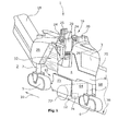
- Fig. 1 shows a road milling machine 1, in particular a large milling machine, with a machine frame 8 and a chassis 4 with in the direction of travel 31 front and rear drives 5.6.
- the drives 5.6 form a steerable front axle and steerable rear axle.
- the chassis 4 is connected via lifting columns 7 with the machine frame 8, by means of which the distance of the machine frame 8 from a road surface 2 is adjustable.
- Each chassis axle has at least one track drive 5, 6 or a wheel drive.
- a conveyor belt device 18 which is pivotable in the vertical and lateral directions, is arranged for the removal of the milled material to be milled.
- the front and rear drives 5,6 of the chassis 4 may consist of crawler tracks or wheels.
- the machine frame 8 has substantially vertically and parallel to the longitudinal center axis of the road construction machine 1 extending lateral outer sides 26,28. It is understood that the outer sides 26,28 do not have to be strictly vertical and absolutely parallel to the longitudinal center axis of the road milling machine 1, but that slight deviations are possible.
- the outer side 26,28 is preferably made in one piece, wherein the outer sides 26 and 28 are preferably in a plane.
- a milling drum 12 is arranged, which is mounted with its Fräswalzenachse in a Fräswalzengephaseuse 10.
- the milling drum 12 extends with its one end face 22 to the in Fig. 1 shown as zero side outside 26,28 of the machine frame 8 zoom. On the null side, the corresponding end face 22 of the milling drum is located very close to the outside of the road milling machine, so that it can be milled very closely past road edges or obstacles.
- hydraulic or electric Fräswalzenantriebe 14 are preferably integrated on both sides, which are supplied by arranged on the machine frame 8 hydraulic pumps or generators, which in turn are driven by an internal combustion engine 3, the drive energy for the traction drive, the Milling drive and ancillary equipment provides.
- each a height-adjustable side plate 15 is arranged, which serves as edge protection.
- the milling drum 12 is preferably arranged centrally between the front drive 5 and the rear drive 6 in the direction of travel 31.
- the milling drum 12 is provided with tools 13.
- the milling drum 12 rotates in the view from the right side of Fig. 2 seen in clockwise direction.
- the single milling drum 12 can also be composed of several parts, or for example consist of at least one pushed onto a base roller tube. Likewise, the milling drum can also be composed of several segments.
- a control station 16 which may have two seats 20 with two steering devices 24, which are provided for left- or right-aligned milling along a road. It goes without saying that a control station which can be displaced transversely to the direction of travel can also be used with a seat with associated steering device 24, which can be displaced as required to the left or right side of the road milling machine 1.
- the seat 20 is preferably oriented in such a way to the lateral outer wall 26,28 that the seat 20 at least partially laterally opposite the outer wall 26,28 protrudes.
- the control console 16 with the seat 20 can be moved inwards to allow the most flush as possible past the obstacle.
- the outside 26,28 has a recess 32 in front of the driver's cab 16. This recess 32 allows the observation of the front drive 5 and thus the observation of the current steering angle.
- Fig. 1 the milling drum housing 10 is shown with a raised scraper blade 64, wherein the side plate 15 is raised to show the position of the milling drum 12.
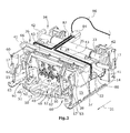
- the milling drum housing 10 is mounted linearly and transversely to the direction of travel 31 on the machine frame 8, as a result of which the zero side can be fixed selectively on one outer side 26, 28 or on the opposite outer side of the machine frame 8.
- the displacement of the Fräswalzengekoruses 10 takes place by means of two spaced in the direction of travel of the machine frame 8 guides 34,36, which are designed as linear guides.
- the first of the linear guides 34 is a pipe guide which fits into the FIGS. 2 to 4 are arranged at the top of the Fräswalzengephaseuses 10.
- the second linear guide 36 is also arranged at a distance at the top of the Fräswalzengephases 10.
- the linear guide takes place between the flat surfaces 37,38, as best from the FIGS. 2 and 3 can be seen.
- the flat surface 37 is provided both on the top and on the underside of a beam 39 which is fixedly secured with flange portions 41 on the underside of the machine frame 8.
- the flat surfaces 37 are comprised of guide members 43 fixedly connected to the milling drum housing 10 and having the flat surfaces 38 in contact with the flat surfaces 37 of the beam 39.
- the distance of the flat surfaces 38 in contact with the respective flat surfaces 37 is adjustable, so that the play between the flat surfaces 37 and 38 can be adjusted by means of the guide members 43.
- the second linear guide 36 forms a floating bearing, while the pipe guide of the first linear guide 34 forms the fixed bearing.
- the pipe guide consists of a stationary over flange 42 on the underside of the machine frame 8 fixed inner tube 33 on which a stationary with the Fräswalzengepur 10 connected hollow cylinder 35 can slide.
- a piston-cylinder unit 45 which is fixed at one end to the machine frame 8 and at the other end to the Fräswalzengeratiuse 10, the entire unit of the Fräswalzengephases 10 with the milling drum 12 and the in the FIGS. 2 and 3 apparent further elements of the Fräswalzengeprocessuses 10, including the lower end 44 of the conveyor belt device 18, between a left-aligned to the outside of the road milling machine 1 or right-aligned position of the milling drum 12 move.
- the stroke of the piston-cylinder unit 45 is preferably between about 500 and about 1000 mm. This means that the Fräswalzengepur 10 with all in the FIGS. 2 and 3 apparent components, this travel can be moved transversely to the direction of travel 31. For example, if the end face of the milling drum 12 in a position on the left side of the machine in the direction of travel 31 on the other side or in the vicinity of the outside 26,28, so is the zero side of the machine on the left side.
- the stroke of the piston-cylinder unit 45 can be seen in relation to the width of the milling drum 12, which in large milling machines is about 1500 mm and more, typically 2000 mm.
- the piston-cylinder unit 45 can apply sufficiently high forces in order to displace the milling drum housing 10 with the milling drum 12 during the milling operation.
- additional tools 13 may be provided on the milling drum at the respective end faces.
- the two linear, spaced in the direction of travel of the machine frame 8 guides 34,36 preferably have a maximum distance from each other. You can transfer the weight of the machine on the Fräswalzengepuruse 10 and mounted on the milling drum 12 to allow high cutting forces at large milling depths.
- the side plate 15 is fastened on both sides to the milling drum housing 10 via a double arrangement of piston-cylinder units 17, the double arrangement allowing a particularly large stroke of the piston-cylinder units 17.
- the exemplary embodiment of a milling drum drive 14 shown can have at least one hydraulic drive 80 which is integrated into the end face 22 of the milling drum 12.
- the illustrated embodiment shows a double-sided hydraulic drive 80 in both end faces 22 of the milling drum 12, wherein hydraulic supply lines 82 are connected to the drives 80 via a manifold 84 and via further hydraulic lines 86 with a driven by the engine 3 hydraulic pump.
- the further hydraulic lines 86 are shown schematically as a single line. It is understood that at least one inlet and -return line is required for the at least one hydraulic drive 80.
- the manifold 84 is fixedly secured to the Fräswalzengephaseuse 10, so that the hydraulic lines 82 need not be flexible and only the other hydraulic lines 86 must be deformable so that the travel of the sliding unit, as shown Fig. 2 can be seen, executed.
- FIGS. 2 and 3 is on the front side of the Fräswalzengephases 10, a belt shoe 40 is arranged, which serves to receive the lower end 44 of the conveyor belt device 18.
- the belt shoe 40 receives the lower end 44 of the conveyor belt device 18.
- the belt shoe 40 is centered to an ejection opening 11 of the Fräswalzengephases 10 arranged and can be adjusted by means of a tracking guide 60 in height.
- the synchronous guide 60 consists of two laterally arranged next to the conveyor belt device 18 joint gears 62, each having a piston-cylinder unit 63, wherein the synchronism of the two linkage 62 is ensured via a coupling shaft 66, so that the synchronization can not tilt.
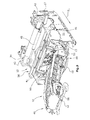
- Fig. 3 shows a representation accordingly Fig. 2 with integrated conveyor belt device 18.
- the front bearing of the conveyor belt device 18 is best in Fig. 5 seen.
- a frame-side support member 56 is stationary.
- the frame-side support member 56 preferably has a convexly rounded support surface, in the embodiment, a tube, on which the front upper end 46 of the transport device 18 can support with a conveyor belt-side support member 52. Since both support members 52,56 have convexly rounded support surfaces, the front end 46 of the conveyor belt device 18 is mounted point-shaped, wherein the storage forms a gimbal joint.
- the conveyor belt-side support member 52 can be displaced in the longitudinal direction when the Fräswalzengephinuse 10 is moved from one side to the other side of the road milling machine 1.
- the articulated mounting also allows a slight rolling of the conveyor belt device 18.
- Lateral guides 54 hold the conveyor belt side support member 52 in position.
- the belt shoe 40 can for pivotally receiving the lower end 44 has a substantially concave, preferably spherical receiving socket 48, which cooperates with one of the shape of the receiving pan 48 adapted underside of the lower end 44 of the conveyor belt device 18.
- This articulated Receiving the lower end 44 of the conveyor belt device 18 allows lifting of the belt shoe 40 with the lower end 44 of the conveyor belt device 18, and a displacement of the Fräswalzengephinuses 10 by a travel of 500 to 1000 mm, the lower end 44 of the conveyor belt device 18 always before the discharge opening 11 of the milling drum housing 10 is arranged.
- the receiving pan 48 is formed by inclined surfaces 50 which receive the lower end 44 of the conveyor belt device 18.
- lateral guide elements 51 are provided which allow a pivoting of the lower end 44 about a vertical axis on the one hand and on the other hand hold the lower end 44 laterally in position.
- the lower end 44 of the conveyor belt device 18 has centrally in the bottom of an in Fig. 2 only shown in phantom, preferably spherical, support means 49 which rests on the belt shoe 40 in the area in front of the middle slope 50 on the belt shoe 40.
- the support member 49 and its support position is also in Fig. 5 shown in dashed lines.
- the ejection opening 11 of the milling drum housing 10 need not be arranged centrally to the Fräswalzengephase 10, but may also be provided eccentrically.
- the tools 13 of the milling drum 12 are arranged spirally in the circumferential direction, wherein the milling drum 12 has opposite spirals of tools 13, which transport the milled material to the ejection opening 11 and convey from the ejection opening 11 to the conveyor belt device 18.
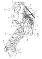
- Fig. 4 shows a rear perspective view of the Fräswalzengepuruses 10, on which a height adjustable by means of piston-cylinder units 65 Abstreiferschild 64 is arranged.
- the scraper blade 64 can also be pivoted upward when the tools 13 on the milling drum 12 must be accessible.
- the scraper blade 64 has on its side facing the milling drum 12 at its lateral outer edges in each case a movable shield element 74, which by means of a resilient biasing means 76 (FIGS. Fig. 4 ) against the milling edge 70 orthogonal to the road surface 2 (FIG. Fig. 1 ) are pressed.
- the lower edge 78 of the laterally movable shield element 74 terminates flush with the lower edge of the scraper blade 64.
- the shield elements 74 are height adjustable together with the Abstreiferschild 64.
- the resilient biasing means 76 may produce the bias in a different manner. In the embodiment of Fig. 4 the biasing means 76 are shown as piston-cylinder elements which can be hydraulically biased.
Landscapes
- Engineering & Computer Science (AREA)
- Mining & Mineral Resources (AREA)
- Architecture (AREA)
- Civil Engineering (AREA)
- Structural Engineering (AREA)
- Mechanical Engineering (AREA)
- Road Repair (AREA)
Priority Applications (1)
| Application Number | Priority Date | Filing Date | Title |
|---|---|---|---|
| EP16201742.0A EP3165676B1 (fr) | 2012-03-08 | 2013-03-05 | Fraiseuse routière automotrice destinée à traiter des surfaces de routes, en particulier grande fraiseuse et procédé d'usinage de surfaces de routes |
Applications Claiming Priority (1)
| Application Number | Priority Date | Filing Date | Title |
|---|---|---|---|
| DE102012203649A DE102012203649A1 (de) | 2012-03-08 | 2012-03-08 | Selbstfahrende Straßenfräsmaschine zum Bearbeiten von Straßenoberflächen, insbesondere Großfräse |
Related Child Applications (2)
| Application Number | Title | Priority Date | Filing Date |
|---|---|---|---|
| EP16201742.0A Division EP3165676B1 (fr) | 2012-03-08 | 2013-03-05 | Fraiseuse routière automotrice destinée à traiter des surfaces de routes, en particulier grande fraiseuse et procédé d'usinage de surfaces de routes |
| EP16201742.0A Division-Into EP3165676B1 (fr) | 2012-03-08 | 2013-03-05 | Fraiseuse routière automotrice destinée à traiter des surfaces de routes, en particulier grande fraiseuse et procédé d'usinage de surfaces de routes |
Publications (2)
| Publication Number | Publication Date |
|---|---|
| EP2636794A1 true EP2636794A1 (fr) | 2013-09-11 |
| EP2636794B1 EP2636794B1 (fr) | 2017-02-22 |
Family
ID=47683780
Family Applications (3)
| Application Number | Title | Priority Date | Filing Date |
|---|---|---|---|
| EP13703629.9A Active EP2823102B1 (fr) | 2012-03-08 | 2013-02-13 | Fraiseuse routière automotrice destinée à usiner des surfaces routières, et procédé d'usinage de surfaces routières |
| EP13157759.5A Active EP2636794B1 (fr) | 2012-03-08 | 2013-03-05 | Grande fraise automotrice destinée au traitement de surfaces routières et procédé de traitement de surfaces routières |
| EP16201742.0A Active EP3165676B1 (fr) | 2012-03-08 | 2013-03-05 | Fraiseuse routière automotrice destinée à traiter des surfaces de routes, en particulier grande fraiseuse et procédé d'usinage de surfaces de routes |
Family Applications Before (1)
| Application Number | Title | Priority Date | Filing Date |
|---|---|---|---|
| EP13703629.9A Active EP2823102B1 (fr) | 2012-03-08 | 2013-02-13 | Fraiseuse routière automotrice destinée à usiner des surfaces routières, et procédé d'usinage de surfaces routières |
Family Applications After (1)
| Application Number | Title | Priority Date | Filing Date |
|---|---|---|---|
| EP16201742.0A Active EP3165676B1 (fr) | 2012-03-08 | 2013-03-05 | Fraiseuse routière automotrice destinée à traiter des surfaces de routes, en particulier grande fraiseuse et procédé d'usinage de surfaces de routes |
Country Status (8)
| Country | Link |
|---|---|
| US (3) | US9416502B2 (fr) |
| EP (3) | EP2823102B1 (fr) |
| JP (8) | JP5950370B2 (fr) |
| CN (3) | CN104160092B (fr) |
| AU (1) | AU2013201364B2 (fr) |
| BR (1) | BR102013005542B1 (fr) |
| DE (1) | DE102012203649A1 (fr) |
| WO (1) | WO2013131726A1 (fr) |
Cited By (2)
| Publication number | Priority date | Publication date | Assignee | Title |
|---|---|---|---|---|
| WO2017167685A1 (fr) * | 2016-04-01 | 2017-10-05 | Ahwi Maschinenbau Gmbh | Dispositif pour véhicule comprenant une unité de broyage |
| EP3333319A1 (fr) * | 2016-12-08 | 2018-06-13 | Wirtgen GmbH | Unité d'actionnement destinée au blocage d'un composant d'une machine de construction et machine de construction dotée d'une telle unité d'actionnement |
Families Citing this family (22)
| Publication number | Priority date | Publication date | Assignee | Title |
|---|---|---|---|---|
| DE102012203649A1 (de) * | 2012-03-08 | 2013-09-12 | Wirtgen Gmbh | Selbstfahrende Straßenfräsmaschine zum Bearbeiten von Straßenoberflächen, insbesondere Großfräse |
| US9328468B2 (en) | 2012-03-08 | 2016-05-03 | Wirtgen Gmbh | Self-propelled road milling machine with adjustable width scraper blade |
| DE202013012325U1 (de) * | 2013-04-09 | 2016-03-29 | Bomag Gmbh | Bodenfräsmaschine, insbesondere Straßenkaltfräse, mit sichtoptimiertem Heckbereich |
| DE102015209740A1 (de) | 2014-12-30 | 2016-06-30 | Wirtgen Gmbh | Selbstfahrende Strassenfräsmaschine zum Bearbeiten von Strassenoberflächen, sowie Verfahren zum Bearbeiten von Strassenoberflächen mit einer Strassenfräsmaschine |
| DE102016108034A1 (de) * | 2016-04-29 | 2017-11-02 | Weber Maschinenbau Gmbh Breidenbach | Vorrichtung zum Aufschneiden eines Lebensmittelprodukts |
| DE102016015499A1 (de) * | 2016-12-23 | 2018-06-28 | Bomag Gmbh | Bodenfräsmaschine, insbesondere Straßenfräsmaschine, und Verfahren zum Betrieb einer Bodenfräsmaschine |
| US10266996B2 (en) * | 2017-08-30 | 2019-04-23 | Caterpillar Paving Products Inc. | Methods and systems for operating a milling machine |
| US10385523B2 (en) * | 2017-12-20 | 2019-08-20 | Caterpillar Paving Products Inc. | Moldboard retention system for a milling machine |
| DE102018202074A1 (de) * | 2018-02-09 | 2019-08-14 | Wirtgen Gmbh | Bodenbearbeitungsmaschine mit steckbarem Bediensitz |
| DE102018006688A1 (de) * | 2018-08-23 | 2020-02-27 | Bomag Gmbh | Bodenfräsmaschine und Verfahren zum Betrieb einer Bodenfräsmaschine |
| JP7190738B2 (ja) * | 2019-01-30 | 2022-12-16 | 範多機械株式会社 | 路面切削機及び路面切削車 |
| CN110387802B (zh) * | 2019-08-05 | 2021-09-10 | 上海道基环保科技有限公司 | 一种道路水泥路面现场全破碎方法以及路面破碎机 |
| GB2593914A (en) * | 2020-04-09 | 2021-10-13 | Caterpillar Paving Products Inc | Milling machine |
| US20250236896A1 (en) | 2020-06-17 | 2025-07-24 | Sumitomo Chemical Company, Limited | Transformant of genus hydrogenophilus bacterium capable of producing aspartic acid and methionine |
| EP4071303B1 (fr) * | 2021-04-06 | 2023-06-14 | BOMAG GmbH | Unité modulaire de fraise |
| US12522986B2 (en) * | 2021-10-29 | 2026-01-13 | Caterpillar Paving Products Inc. | Milling machines, systems, and related methods |
| CN114717923B (zh) * | 2022-03-22 | 2023-01-20 | 湖南三一中益机械有限公司 | 铣刨机尾门控制方法、铣刨工作装置和铣刨机 |
| CN114875757B (zh) * | 2022-05-09 | 2025-07-08 | 柳工无锡路面机械有限公司 | 一种轮式路面铣刨机的底盘调节装置 |
| CN114837049B (zh) * | 2022-05-24 | 2023-06-06 | 徐州徐工筑路机械有限公司 | 一种适用于冷再生机双向工作的铣拌仓室料门系统 |
| CN115240157B (zh) * | 2022-08-05 | 2023-07-18 | 禾多科技(北京)有限公司 | 道路场景数据持久化方法、装置、设备和计算机可读介质 |
| CN115897353A (zh) * | 2022-11-27 | 2023-04-04 | 赵邦明 | 一种混凝土铣刨机 |
| US20240368848A1 (en) * | 2023-05-01 | 2024-11-07 | Caterpillar Paving Products Inc. | Systems and methods of segmented anti-slabbing for milling machines |
Citations (10)
| Publication number | Priority date | Publication date | Assignee | Title |
|---|---|---|---|---|
| US3767262A (en) * | 1971-11-17 | 1973-10-23 | Greenside Machine Co Ltd | Road cutting machine with laterally extensible drum and method |
| DE2420330A1 (de) * | 1974-04-26 | 1975-11-06 | Hackmack Alfred | Vorrichtung zum abtragen von strassenoberflaechen |
| DE2540047A1 (de) * | 1975-09-09 | 1977-03-17 | Marks & Co | Fahrzeug mit hoehenverstellbarer fraeswalze |
| DE8315139U1 (de) | 1983-05-21 | 1984-02-09 | Marks GmbH, 4353 Oer-Erkenschwick | Fraesmaschine |
| DE3409389A1 (de) * | 1984-03-14 | 1985-10-03 | Reinhard 5461 Windhagen Wirtgen | Maschine zum abfraesen oder abschaelen von strassenbelaegen |
| EP0685598A1 (fr) * | 1994-05-31 | 1995-12-06 | Ingersoll-Rand Company | Mécanismus d'accès pour tambour |
| EP0752501A1 (fr) | 1995-07-04 | 1997-01-08 | Ohkita Engineering Co., Ltd. | Excavateur de route à élément de coupe cylindrique |
| DE19726122A1 (de) | 1997-06-20 | 1999-01-28 | Wirtgen Gmbh | Vorrichtung zum Abfräsen von Bodenbelägen, insbesondere Fahrbahnen |
| DE19814053A1 (de) * | 1998-03-30 | 1999-10-07 | Wirtgen Gmbh | Vorrichtung zum Abfräsen von Bodenflächen, insbesondere Fahrbahnen |
| EP2011921A2 (fr) | 2007-07-05 | 2009-01-07 | Wirtgen GmbH | Dispositif de fraisage de route automobile, en particulier grande fraiseuse |
Family Cites Families (38)
| Publication number | Priority date | Publication date | Assignee | Title |
|---|---|---|---|---|
| US4197032A (en) * | 1978-08-02 | 1980-04-08 | Power Curbers, Inc. | Apparatus and method for forming a continuous strip of paving |
| JPS6126417Y2 (fr) * | 1981-04-02 | 1986-08-08 | ||
| JPS591714U (ja) * | 1982-06-28 | 1984-01-07 | 酒井重工業株式会社 | ロ−ド切削機 |
| DE3508884A1 (de) * | 1984-03-14 | 1986-09-25 | Reinhard 5461 Windhagen Wirtgen | Maschine zum abfraesen oder abschaelen von strassenbelaegen |
| JPH0315611Y2 (fr) * | 1986-04-16 | 1991-04-04 | ||
| US4808026A (en) * | 1987-11-27 | 1989-02-28 | Power Curbers, Inc. | Construction apparatus with earth trimmer |
| DE3823480C1 (en) | 1988-07-11 | 1989-10-26 | Reinhard 5461 Windhagen De Wirtgen | Collecting plate for surface-cutting machines |
| DE4039166A1 (de) | 1990-12-07 | 1992-06-11 | Adolf Wuerth Gmbh & Co Kg | Einrichtung zum aufbewahren und ausgeben von verkaufseinheiten |
| US5203615A (en) * | 1991-12-30 | 1993-04-20 | Alitec Corporation | Full side shift system for detachable rotary apparatus |
| JPH061411U (ja) * | 1992-06-18 | 1994-01-11 | 株式会社小松エスト | 路面切削機の廃材除去装置 |
| US5382084A (en) | 1993-07-28 | 1995-01-17 | Alitec Corporation | Milling drum with internal drive motor |
| US5505598A (en) * | 1994-07-29 | 1996-04-09 | Wirtgen America, Inc. | Milling machine with multi-width cutter |
| JPH0921107A (ja) | 1995-07-04 | 1997-01-21 | Okita Engineering:Kk | 舗装道路の掘削方法 |
| ATE204625T1 (de) * | 1995-10-31 | 2001-09-15 | Bitelli Spa | Einsatz-element zur aufnahme wenigstens eines fräswerkzeuges, das auf frästrommeln von arbeitsmaschinen zur entfernung von böden anzubringen ist |
| JP3474361B2 (ja) | 1996-06-05 | 2003-12-08 | 株式会社大北エンジニアリング | 舗装道路用の掘削作業車 |
| US6116699A (en) * | 1998-07-29 | 2000-09-12 | Clark Equipment Company | Planer with edge planing capability |
| DE10223819B4 (de) | 2002-05-28 | 2005-05-12 | Wirtgen Gmbh | Fräsmaschine zum Bearbeiten von Bodenoberflächen, sowie Verfahren zum Entsorgen von während der Fräsbearbeitung entstehenden Stäuben und Dämpfen an einer Fräsmaschine |
| DE10247579B3 (de) | 2002-10-11 | 2004-04-15 | Wirtgen Gmbh | Abstreifeinrichtung für Fräswalzen einer Baumaschine, sowie Verfahren |
| DE10347874A1 (de) | 2003-10-10 | 2005-05-12 | Wirtgen Gmbh | Hecklader-Straßenfräßmaschine mit höhenverstellbarer Abdichtungseinrichtung |
| JP4299119B2 (ja) * | 2003-12-24 | 2009-07-22 | 株式会社小松製作所 | 作業車両の作業機支持機構 |
| DE102004007716B3 (de) * | 2004-02-16 | 2005-06-16 | Wirtgen Gmbh | Fräsmaschine sowie Verfahren zum Bearbeiten von Bodenoberflächen |
| US7131704B2 (en) * | 2004-09-23 | 2006-11-07 | Wirtgen America, Inc. | Shiftable conveyor for road milling machine |
| DE102005058102B3 (de) | 2005-12-05 | 2007-03-01 | Wirtgen Gmbh | Abstreifeinrichtung für Fräswalzen einer Baumaschine |
| US7854566B2 (en) | 2006-12-01 | 2010-12-21 | Hall David R | Nozzles incorporated into a milling machine |
| BRPI0713752B1 (pt) * | 2006-12-22 | 2018-03-13 | Wirtgen Gmbh | Fresadora para estrada e método para posicionar a estrutura da máquina paralela ao terreno |
| US7748789B2 (en) * | 2007-05-25 | 2010-07-06 | Freeburn Charles W | Pavement profiler |
| DE102007038677B4 (de) * | 2007-08-15 | 2009-09-17 | Wirtgen Gmbh | Abstreifeinrichtung, sowie Baumaschine |
| CN101970759B (zh) * | 2008-03-12 | 2014-05-07 | 马林公司 | 用于磨削路面的改进的刨路机 |
| JP5180775B2 (ja) * | 2008-10-24 | 2013-04-10 | 酒井重工業株式会社 | 路面切削装置 |
| JP4783419B2 (ja) * | 2008-12-09 | 2011-09-28 | 住友建機株式会社 | 舗装機械における伸縮可能なリテーニングプレート装置 |
| DE102009059064B4 (de) | 2009-12-18 | 2012-04-26 | Wirtgen Gmbh | Selbstfahrende Straßenfräsmaschine |
| CN101736677B (zh) * | 2009-12-30 | 2011-12-14 | 山东省路桥集团有限公司 | 就地热再生复拌机斜刮板式输送机 |
| DE102010013983B4 (de) * | 2010-04-06 | 2016-01-21 | Bomag Gmbh | Fräswalze für eine Bodenfräsmaschine und Bodenfräsmaschine |
| US8256847B2 (en) * | 2010-11-30 | 2012-09-04 | Hall David R | Rotational milling chamber |
| CN202073018U (zh) * | 2011-05-07 | 2011-12-14 | 徐州徐工筑路机械有限公司 | 后输料铣刨机刮板浮动液压控制系统 |
| US20130195554A1 (en) | 2012-01-27 | 2013-08-01 | Caterpillar Paving Products Inc. | Moldboard lock |
| DE102012203649A1 (de) * | 2012-03-08 | 2013-09-12 | Wirtgen Gmbh | Selbstfahrende Straßenfräsmaschine zum Bearbeiten von Straßenoberflächen, insbesondere Großfräse |
| DE102014007907B4 (de) | 2013-06-07 | 2024-07-04 | Bomag Gmbh | Abstreifeinrichtung mit einer Abstreiferleiste für eine Bodenfräsmaschine und Bodenfräsmaschine mit einer Abstreifeinrichtung |
-
2012
- 2012-03-08 DE DE102012203649A patent/DE102012203649A1/de not_active Withdrawn
-
2013
- 2013-02-13 EP EP13703629.9A patent/EP2823102B1/fr active Active
- 2013-02-13 JP JP2014560293A patent/JP5950370B2/ja active Active
- 2013-02-13 WO PCT/EP2013/052895 patent/WO2013131726A1/fr not_active Ceased
- 2013-02-13 CN CN201380013131.7A patent/CN104160092B/zh active Active
- 2013-03-05 EP EP13157759.5A patent/EP2636794B1/fr active Active
- 2013-03-05 EP EP16201742.0A patent/EP3165676B1/fr active Active
- 2013-03-06 US US13/786,940 patent/US9416502B2/en active Active
- 2013-03-07 BR BR102013005542-5A patent/BR102013005542B1/pt active IP Right Grant
- 2013-03-08 JP JP2013046747A patent/JP5598826B2/ja active Active
- 2013-03-08 CN CN201310075207.0A patent/CN103306187B/zh active Active
- 2013-03-08 AU AU2013201364A patent/AU2013201364B2/en active Active
- 2013-03-08 CN CN201320106700XU patent/CN203229862U/zh not_active Expired - Lifetime
-
2014
- 2014-08-01 JP JP2014157748A patent/JP6038846B2/ja active Active
-
2016
- 2016-08-10 US US15/232,905 patent/US10450709B2/en active Active
- 2016-11-02 JP JP2016215255A patent/JP6429157B2/ja active Active
-
2018
- 2018-04-09 JP JP2018074655A patent/JP6690854B2/ja active Active
-
2019
- 2019-10-17 US US16/655,957 patent/US20200141072A1/en not_active Abandoned
-
2020
- 2020-04-06 JP JP2020068633A patent/JP7169317B2/ja active Active
-
2021
- 2021-08-16 JP JP2021132269A patent/JP7168737B2/ja active Active
-
2022
- 2022-10-27 JP JP2022172127A patent/JP7560522B2/ja active Active
Patent Citations (10)
| Publication number | Priority date | Publication date | Assignee | Title |
|---|---|---|---|---|
| US3767262A (en) * | 1971-11-17 | 1973-10-23 | Greenside Machine Co Ltd | Road cutting machine with laterally extensible drum and method |
| DE2420330A1 (de) * | 1974-04-26 | 1975-11-06 | Hackmack Alfred | Vorrichtung zum abtragen von strassenoberflaechen |
| DE2540047A1 (de) * | 1975-09-09 | 1977-03-17 | Marks & Co | Fahrzeug mit hoehenverstellbarer fraeswalze |
| DE8315139U1 (de) | 1983-05-21 | 1984-02-09 | Marks GmbH, 4353 Oer-Erkenschwick | Fraesmaschine |
| DE3409389A1 (de) * | 1984-03-14 | 1985-10-03 | Reinhard 5461 Windhagen Wirtgen | Maschine zum abfraesen oder abschaelen von strassenbelaegen |
| EP0685598A1 (fr) * | 1994-05-31 | 1995-12-06 | Ingersoll-Rand Company | Mécanismus d'accès pour tambour |
| EP0752501A1 (fr) | 1995-07-04 | 1997-01-08 | Ohkita Engineering Co., Ltd. | Excavateur de route à élément de coupe cylindrique |
| DE19726122A1 (de) | 1997-06-20 | 1999-01-28 | Wirtgen Gmbh | Vorrichtung zum Abfräsen von Bodenbelägen, insbesondere Fahrbahnen |
| DE19814053A1 (de) * | 1998-03-30 | 1999-10-07 | Wirtgen Gmbh | Vorrichtung zum Abfräsen von Bodenflächen, insbesondere Fahrbahnen |
| EP2011921A2 (fr) | 2007-07-05 | 2009-01-07 | Wirtgen GmbH | Dispositif de fraisage de route automobile, en particulier grande fraiseuse |
Cited By (3)
| Publication number | Priority date | Publication date | Assignee | Title |
|---|---|---|---|---|
| WO2017167685A1 (fr) * | 2016-04-01 | 2017-10-05 | Ahwi Maschinenbau Gmbh | Dispositif pour véhicule comprenant une unité de broyage |
| EP3333319A1 (fr) * | 2016-12-08 | 2018-06-13 | Wirtgen GmbH | Unité d'actionnement destinée au blocage d'un composant d'une machine de construction et machine de construction dotée d'une telle unité d'actionnement |
| US10590612B2 (en) | 2016-12-08 | 2020-03-17 | Wirtgen Gmbh | Actuating unit for locking a component of a construction machine |
Also Published As
Similar Documents
| Publication | Publication Date | Title |
|---|---|---|
| EP2636794B1 (fr) | Grande fraise automotrice destinée au traitement de surfaces routières et procédé de traitement de surfaces routières | |
| EP1704283B1 (fr) | Machine automotrice servant a realiser des voies de circulation | |
| EP0756656B1 (fr) | Engin pour travaux routiers | |
| EP2011921B1 (fr) | Grande fraiseuse de route automobile | |
| DE102013208484B4 (de) | Vorrichtung zum Bearbeiten von Straßen- oder Bodenoberflächen, sowie Verfahren zum Lenken einer Straßenfräsmaschine | |
| EP1522632A1 (fr) | Dispositif roulant et finisseuse à coffrage glissant comprenant un tel dispositif roulant | |
| DE1944214A1 (de) | Drehkran-Fahrgestell | |
| EP2801664B1 (fr) | Fraiseuse routière destinée à traiter les surfaces routières et de sol | |
| DE69118698T2 (de) | Verfahrbare bodenschleifmaschine | |
| DE102013009816A1 (de) | Bodenfräsmaschine, insbesondere Straßenkaltfräse | |
| EP1841637B1 (fr) | Machine de construction et dispositif de rotation | |
| DE102014000236B4 (de) | Bodenfräsmaschine mit einer Baumaschinenlenkeinrichtung | |
| DE9406572U1 (de) | Fahrwerk, insbesondere für mobile Arbeitsgeräte und Fahrzeuge | |
| DE1946391A1 (de) | Strassenbetoniermaschine | |
| EP0638471B1 (fr) | Machine de construction | |
| EP0681063A2 (fr) | Fraiseuse | |
| EP3524736A1 (fr) | Machine de traitement du sol pourvue d'un panneau d'accès pour l'entretien avec zone de stockage et siege | |
| EP3480359B1 (fr) | Dispositif de construction de voies ferrées destiné au traitement de rails à gorge | |
| AT395877B (de) | Einrichtung zum aufrauhen und einebnen einer mit hartschnee bedeckten und/oder vereisten verkehrsflaeche | |
| DE102020006837A1 (de) | Selbstfahrende Bodenfräsmaschine | |
| EP4368481B1 (fr) | Fraiseuse routière, procédé de conduite d'une fraiseuse routière et procédé de positionnement | |
| DE102013007161A1 (de) | Bodenfräsmaschine, insbesondere Recycler oder Bodenstabilisierer |
Legal Events
| Date | Code | Title | Description |
|---|---|---|---|
| PUAI | Public reference made under article 153(3) epc to a published international application that has entered the european phase |
Free format text: ORIGINAL CODE: 0009012 |
|
| AK | Designated contracting states |
Kind code of ref document: A1 Designated state(s): AL AT BE BG CH CY CZ DE DK EE ES FI FR GB GR HR HU IE IS IT LI LT LU LV MC MK MT NL NO PL PT RO RS SE SI SK SM TR |
|
| AX | Request for extension of the european patent |
Extension state: BA ME |
|
| 17P | Request for examination filed |
Effective date: 20140311 |
|
| RBV | Designated contracting states (corrected) |
Designated state(s): AL AT BE BG CH CY CZ DE DK EE ES FI FR GB GR HR HU IE IS IT LI LT LU LV MC MK MT NL NO PL PT RO RS SE SI SK SM TR |
|
| 17Q | First examination report despatched |
Effective date: 20141008 |
|
| TPAC | Observations filed by third parties |
Free format text: ORIGINAL CODE: EPIDOSNTIPA |
|
| GRAP | Despatch of communication of intention to grant a patent |
Free format text: ORIGINAL CODE: EPIDOSNIGR1 |
|
| INTG | Intention to grant announced |
Effective date: 20160819 |
|
| STAA | Information on the status of an ep patent application or granted ep patent |
Free format text: STATUS: GRANT OF PATENT IS INTENDED |
|
| GRAS | Grant fee paid |
Free format text: ORIGINAL CODE: EPIDOSNIGR3 |
|
| GRAA | (expected) grant |
Free format text: ORIGINAL CODE: 0009210 |
|
| STAA | Information on the status of an ep patent application or granted ep patent |
Free format text: STATUS: THE PATENT HAS BEEN GRANTED |
|
| AK | Designated contracting states |
Kind code of ref document: B1 Designated state(s): AL AT BE BG CH CY CZ DE DK EE ES FI FR GB GR HR HU IE IS IT LI LT LU LV MC MK MT NL NO PL PT RO RS SE SI SK SM TR |
|
| REG | Reference to a national code |
Ref country code: GB Ref legal event code: FG4D Free format text: NOT ENGLISH |
|
| REG | Reference to a national code |
Ref country code: CH Ref legal event code: EP |
|
| REG | Reference to a national code |
Ref country code: AT Ref legal event code: REF Ref document number: 869396 Country of ref document: AT Kind code of ref document: T Effective date: 20170315 |
|
| REG | Reference to a national code |
Ref country code: IE Ref legal event code: FG4D Free format text: LANGUAGE OF EP DOCUMENT: GERMAN |
|
| REG | Reference to a national code |
Ref country code: DE Ref legal event code: R096 Ref document number: 502013006405 Country of ref document: DE |
|
| REG | Reference to a national code |
Ref country code: FR Ref legal event code: PLFP Year of fee payment: 5 |
|
| REG | Reference to a national code |
Ref country code: SE Ref legal event code: TRGR |
|
| REG | Reference to a national code |
Ref country code: LT Ref legal event code: MG4D |
|
| REG | Reference to a national code |
Ref country code: NL Ref legal event code: MP Effective date: 20170222 |
|
| PG25 | Lapsed in a contracting state [announced via postgrant information from national office to epo] |
Ref country code: FI Free format text: LAPSE BECAUSE OF FAILURE TO SUBMIT A TRANSLATION OF THE DESCRIPTION OR TO PAY THE FEE WITHIN THE PRESCRIBED TIME-LIMIT Effective date: 20170222 Ref country code: GR Free format text: LAPSE BECAUSE OF FAILURE TO SUBMIT A TRANSLATION OF THE DESCRIPTION OR TO PAY THE FEE WITHIN THE PRESCRIBED TIME-LIMIT Effective date: 20170523 Ref country code: HR Free format text: LAPSE BECAUSE OF FAILURE TO SUBMIT A TRANSLATION OF THE DESCRIPTION OR TO PAY THE FEE WITHIN THE PRESCRIBED TIME-LIMIT Effective date: 20170222 Ref country code: NO Free format text: LAPSE BECAUSE OF FAILURE TO SUBMIT A TRANSLATION OF THE DESCRIPTION OR TO PAY THE FEE WITHIN THE PRESCRIBED TIME-LIMIT Effective date: 20170522 Ref country code: LT Free format text: LAPSE BECAUSE OF FAILURE TO SUBMIT A TRANSLATION OF THE DESCRIPTION OR TO PAY THE FEE WITHIN THE PRESCRIBED TIME-LIMIT Effective date: 20170222 |
|
| PG25 | Lapsed in a contracting state [announced via postgrant information from national office to epo] |
Ref country code: BG Free format text: LAPSE BECAUSE OF FAILURE TO SUBMIT A TRANSLATION OF THE DESCRIPTION OR TO PAY THE FEE WITHIN THE PRESCRIBED TIME-LIMIT Effective date: 20170522 Ref country code: PT Free format text: LAPSE BECAUSE OF FAILURE TO SUBMIT A TRANSLATION OF THE DESCRIPTION OR TO PAY THE FEE WITHIN THE PRESCRIBED TIME-LIMIT Effective date: 20170622 Ref country code: ES Free format text: LAPSE BECAUSE OF FAILURE TO SUBMIT A TRANSLATION OF THE DESCRIPTION OR TO PAY THE FEE WITHIN THE PRESCRIBED TIME-LIMIT Effective date: 20170222 Ref country code: NL Free format text: LAPSE BECAUSE OF FAILURE TO SUBMIT A TRANSLATION OF THE DESCRIPTION OR TO PAY THE FEE WITHIN THE PRESCRIBED TIME-LIMIT Effective date: 20170222 Ref country code: RS Free format text: LAPSE BECAUSE OF FAILURE TO SUBMIT A TRANSLATION OF THE DESCRIPTION OR TO PAY THE FEE WITHIN THE PRESCRIBED TIME-LIMIT Effective date: 20170222 Ref country code: LV Free format text: LAPSE BECAUSE OF FAILURE TO SUBMIT A TRANSLATION OF THE DESCRIPTION OR TO PAY THE FEE WITHIN THE PRESCRIBED TIME-LIMIT Effective date: 20170222 |
|
| PG25 | Lapsed in a contracting state [announced via postgrant information from national office to epo] |
Ref country code: SK Free format text: LAPSE BECAUSE OF FAILURE TO SUBMIT A TRANSLATION OF THE DESCRIPTION OR TO PAY THE FEE WITHIN THE PRESCRIBED TIME-LIMIT Effective date: 20170222 Ref country code: RO Free format text: LAPSE BECAUSE OF FAILURE TO SUBMIT A TRANSLATION OF THE DESCRIPTION OR TO PAY THE FEE WITHIN THE PRESCRIBED TIME-LIMIT Effective date: 20170222 Ref country code: CZ Free format text: LAPSE BECAUSE OF FAILURE TO SUBMIT A TRANSLATION OF THE DESCRIPTION OR TO PAY THE FEE WITHIN THE PRESCRIBED TIME-LIMIT Effective date: 20170222 Ref country code: EE Free format text: LAPSE BECAUSE OF FAILURE TO SUBMIT A TRANSLATION OF THE DESCRIPTION OR TO PAY THE FEE WITHIN THE PRESCRIBED TIME-LIMIT Effective date: 20170222 |
|
| REG | Reference to a national code |
Ref country code: CH Ref legal event code: PL |
|
| REG | Reference to a national code |
Ref country code: DE Ref legal event code: R097 Ref document number: 502013006405 Country of ref document: DE |
|
| PG25 | Lapsed in a contracting state [announced via postgrant information from national office to epo] |
Ref country code: MC Free format text: LAPSE BECAUSE OF FAILURE TO SUBMIT A TRANSLATION OF THE DESCRIPTION OR TO PAY THE FEE WITHIN THE PRESCRIBED TIME-LIMIT Effective date: 20170222 Ref country code: PL Free format text: LAPSE BECAUSE OF FAILURE TO SUBMIT A TRANSLATION OF THE DESCRIPTION OR TO PAY THE FEE WITHIN THE PRESCRIBED TIME-LIMIT Effective date: 20170222 Ref country code: DK Free format text: LAPSE BECAUSE OF FAILURE TO SUBMIT A TRANSLATION OF THE DESCRIPTION OR TO PAY THE FEE WITHIN THE PRESCRIBED TIME-LIMIT Effective date: 20170222 Ref country code: SM Free format text: LAPSE BECAUSE OF FAILURE TO SUBMIT A TRANSLATION OF THE DESCRIPTION OR TO PAY THE FEE WITHIN THE PRESCRIBED TIME-LIMIT Effective date: 20170222 |
|
| REG | Reference to a national code |
Ref country code: IE Ref legal event code: MM4A |
|
| PLBE | No opposition filed within time limit |
Free format text: ORIGINAL CODE: 0009261 |
|
| STAA | Information on the status of an ep patent application or granted ep patent |
Free format text: STATUS: NO OPPOSITION FILED WITHIN TIME LIMIT |
|
| 26N | No opposition filed |
Effective date: 20171123 |
|
| PG25 | Lapsed in a contracting state [announced via postgrant information from national office to epo] |
Ref country code: LU Free format text: LAPSE BECAUSE OF NON-PAYMENT OF DUE FEES Effective date: 20170305 |
|
| PG25 | Lapsed in a contracting state [announced via postgrant information from national office to epo] |
Ref country code: CH Free format text: LAPSE BECAUSE OF NON-PAYMENT OF DUE FEES Effective date: 20170331 Ref country code: IE Free format text: LAPSE BECAUSE OF NON-PAYMENT OF DUE FEES Effective date: 20170305 Ref country code: SI Free format text: LAPSE BECAUSE OF FAILURE TO SUBMIT A TRANSLATION OF THE DESCRIPTION OR TO PAY THE FEE WITHIN THE PRESCRIBED TIME-LIMIT Effective date: 20170222 Ref country code: LI Free format text: LAPSE BECAUSE OF NON-PAYMENT OF DUE FEES Effective date: 20170331 |
|
| REG | Reference to a national code |
Ref country code: BE Ref legal event code: MM Effective date: 20170331 |
|
| REG | Reference to a national code |
Ref country code: FR Ref legal event code: PLFP Year of fee payment: 6 |
|
| PG25 | Lapsed in a contracting state [announced via postgrant information from national office to epo] |
Ref country code: BE Free format text: LAPSE BECAUSE OF NON-PAYMENT OF DUE FEES Effective date: 20170331 |
|
| PG25 | Lapsed in a contracting state [announced via postgrant information from national office to epo] |
Ref country code: MT Free format text: LAPSE BECAUSE OF FAILURE TO SUBMIT A TRANSLATION OF THE DESCRIPTION OR TO PAY THE FEE WITHIN THE PRESCRIBED TIME-LIMIT Effective date: 20170222 |
|
| REG | Reference to a national code |
Ref country code: AT Ref legal event code: MM01 Ref document number: 869396 Country of ref document: AT Kind code of ref document: T Effective date: 20180305 |
|
| PG25 | Lapsed in a contracting state [announced via postgrant information from national office to epo] |
Ref country code: HU Free format text: LAPSE BECAUSE OF FAILURE TO SUBMIT A TRANSLATION OF THE DESCRIPTION OR TO PAY THE FEE WITHIN THE PRESCRIBED TIME-LIMIT; INVALID AB INITIO Effective date: 20130305 |
|
| PG25 | Lapsed in a contracting state [announced via postgrant information from national office to epo] |
Ref country code: AT Free format text: LAPSE BECAUSE OF NON-PAYMENT OF DUE FEES Effective date: 20180305 Ref country code: CY Free format text: LAPSE BECAUSE OF NON-PAYMENT OF DUE FEES Effective date: 20170222 |
|
| PG25 | Lapsed in a contracting state [announced via postgrant information from national office to epo] |
Ref country code: MK Free format text: LAPSE BECAUSE OF FAILURE TO SUBMIT A TRANSLATION OF THE DESCRIPTION OR TO PAY THE FEE WITHIN THE PRESCRIBED TIME-LIMIT Effective date: 20170222 |
|
| PG25 | Lapsed in a contracting state [announced via postgrant information from national office to epo] |
Ref country code: TR Free format text: LAPSE BECAUSE OF FAILURE TO SUBMIT A TRANSLATION OF THE DESCRIPTION OR TO PAY THE FEE WITHIN THE PRESCRIBED TIME-LIMIT Effective date: 20170222 |
|
| PG25 | Lapsed in a contracting state [announced via postgrant information from national office to epo] |
Ref country code: AL Free format text: LAPSE BECAUSE OF FAILURE TO SUBMIT A TRANSLATION OF THE DESCRIPTION OR TO PAY THE FEE WITHIN THE PRESCRIBED TIME-LIMIT Effective date: 20170222 Ref country code: IS Free format text: LAPSE BECAUSE OF FAILURE TO SUBMIT A TRANSLATION OF THE DESCRIPTION OR TO PAY THE FEE WITHIN THE PRESCRIBED TIME-LIMIT Effective date: 20170622 |
|
| P01 | Opt-out of the competence of the unified patent court (upc) registered |
Effective date: 20230525 |
|
| PGFP | Annual fee paid to national office [announced via postgrant information from national office to epo] |
Ref country code: IT Payment date: 20250331 Year of fee payment: 13 |
|
| PGFP | Annual fee paid to national office [announced via postgrant information from national office to epo] |
Ref country code: SE Payment date: 20260323 Year of fee payment: 14 |
|
| PGFP | Annual fee paid to national office [announced via postgrant information from national office to epo] |
Ref country code: GB Payment date: 20260324 Year of fee payment: 14 |
|
| PGFP | Annual fee paid to national office [announced via postgrant information from national office to epo] |
Ref country code: DE Payment date: 20260320 Year of fee payment: 14 |
|
| PGFP | Annual fee paid to national office [announced via postgrant information from national office to epo] |
Ref country code: FR Payment date: 20260324 Year of fee payment: 14 |