EP2636932A1 - Klemmventil mit integrierter Druckkammer - Google Patents
Klemmventil mit integrierter Druckkammer Download PDFInfo
- Publication number
- EP2636932A1 EP2636932A1 EP13001222.2A EP13001222A EP2636932A1 EP 2636932 A1 EP2636932 A1 EP 2636932A1 EP 13001222 A EP13001222 A EP 13001222A EP 2636932 A1 EP2636932 A1 EP 2636932A1
- Authority
- EP
- European Patent Office
- Prior art keywords
- wall
- valve
- pressurized gas
- seal
- isolation valve
- Prior art date
- Legal status (The legal status is an assumption and is not a legal conclusion. Google has not performed a legal analysis and makes no representation as to the accuracy of the status listed.)
- Granted
Links
Images




Classifications
-
- F—MECHANICAL ENGINEERING; LIGHTING; HEATING; WEAPONS; BLASTING
- F16—ENGINEERING ELEMENTS AND UNITS; GENERAL MEASURES FOR PRODUCING AND MAINTAINING EFFECTIVE FUNCTIONING OF MACHINES OR INSTALLATIONS; THERMAL INSULATION IN GENERAL
- F16K—VALVES; TAPS; COCKS; ACTUATING-FLOATS; DEVICES FOR VENTING OR AERATING
- F16K7/00—Diaphragm valves or cut-off apparatus, e.g. with a member deformed, but not moved bodily, to close the passage ; Pinch valves
- F16K7/02—Diaphragm valves or cut-off apparatus, e.g. with a member deformed, but not moved bodily, to close the passage ; Pinch valves with tubular diaphragm
- F16K7/04—Diaphragm valves or cut-off apparatus, e.g. with a member deformed, but not moved bodily, to close the passage ; Pinch valves with tubular diaphragm constrictable by external radial force
- F16K7/07—Diaphragm valves or cut-off apparatus, e.g. with a member deformed, but not moved bodily, to close the passage ; Pinch valves with tubular diaphragm constrictable by external radial force by means of fluid pressure
Definitions
- the present invention is generally directed toward a pinch-type isolation valve comprising an integrated pressurized gas reservoir.
- the pressurized gas reservoir stores sufficient pressurized gas on board the valve to effect the collapse of an internal sleeve carried by the valve, which closes the valve.
- Isolation valves including pinch-type valves
- pinch-type valves have been used to control the flow of fluid or particulate material, such as grain, through a conduit, and also to prevent propagation of hazardous conditions, such as fires and explosions, through interconnecting pipes or conveying lines to additional process equipment or operating locations.
- hazardous conditions such as fires and explosions
- pinch valve designs have been proposed for various applications.
- U.S. Patent No. 7,246,786 to Schmidt et al. is directed toward a mechanical pinch-type isolation valve for controlling fluid flow in industrial applications.
- This mechanical valve includes a pair of rotating pinch elements that impinge a rubber spool so as block the flow of material therethrough.
- U.S. Patent No. 5,107,883 to Shaw is directed toward a slow, variable-response pinch valve control system having a network of pinch valves (e.g. for waterlines in a building to reduce/prevent water hammer).
- Each pinch valve includes a single solenoid operable to rotatably pivot between a first orientation, where compressed gas is directed from a first passageway connected to a source to an inner chamber defined by a sleeve and outer wall of the waterline, and a second orientation, where compressed gas is exhausted from the chamber through a second passageway.
- U.S. Patent No. 5,771,665 to Nelson et al. is directed toward a sand-bagging system and includes a pinch valve that comprises a chamber with laterally-aligned apertures on the sidewall thereof that provide fluid communication between the chamber and a flexible tubular wall and air lines connected to the apertures.
- a three-way pilot valve permits introduction or evacuation of air via through the lines to compress or expand the wall.
- Embodiments according to the present invention seek to mitigate reliance upon external power and compressed air resources for valve operation thus preserving the valve's operational readiness even under extreme circumstances. Further, valve response time is enhanced by being able to rapidly deliver a pressurized gas to impinge upon the valve's flexible sleeve and close the valve.
- an isolation valve comprising a valve body outer wall and a valve body inner wall.
- the outer and inner walls cooperate to define at least in part a pressurized gas reservoir.
- a flexible sleeve is disposed within the inner wall.
- the sleeve and inner wall cooperate to define, at least in part, a gas-receiving chamber.
- the valve further includes at least one actuator assembly configured upon actuation to cause a gas stored in the reservoir to flow into the chamber and effect closure of the valve.
- an isolation valve comprising a tubular outer wall, a tubular inner wall disposed at least in part within the tubular outer wall, and a flexible sleeve disposed at least in part within the inner wall.
- the flexible sleeve is shiftable between a valve open configuration and a valve closed configuration.
- the inner and outer walls cooperate to define, at least in part, a pressurized gas reservoir.
- the inner wall and flexible sleeve cooperate to define, at least in part, a gas-receiving chamber.
- the pressurized gas reservoir and gas-receiving chamber are interconnected by at least one passageway.
- At least one actuator assembly is provided and configured to block communication between the pressurized gas reservoir and the gas-receiving chamber through the passageway while the valve is in said valve open configuration.
- the at least one actuator assembly is shiftable upon actuation to unblock the passageway thereby permitting flow of pressurized gas from the reservoir to the chamber and causing the valve to shift to the valve closed configuration.
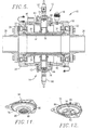
- Valve 10 comprises a pair of actuator assemblies 12, 14 (see, Fig. 2 ) secured to a valve body outer wall 16.
- actuator assemblies 12, 14 The construction and operation of actuator assemblies 12, 14 is explained in greater detail below.
- outer wall 16 is substantially cylindrical, although, it is sufficient for the outer wall to be merely tubular in form.
- a pair of end caps 18, 20 are attached to respective ends of outer wall 16 and provide points for coupling flanges 22, 24 and their associated pipe sections 26, 28. End caps 18, 20 may also be equipped with eye bolts 29 to assist with mounting of valve 10 within a plant.
- a valve body inner wall 30 is located inside and is generally coaxial with outer wall 16.
- a flexible sleeve 32 made from an elastomeric material, is located within inner wall 30 and defines a gas-receiving chamber 39.
- inner wall 30 is tubular and irregularly shaped as compared with outer wall 16.
- Inner wall 30 comprises a pair of generally cylindrical end sections 34, 36 that are secured to end caps 18, 20, respectively, by bolt assemblies 27. End sections 34, 36 are interconnected by a central segment 38 that bulges toward outer wall 16.
- Bulged segment 38 defines a relief zone 40 that provides an area capable of accommodating a collapsed sleeve 32 upon actuation of valve 10 (see, Fig. 8 ).
- bulged segment 38 includes a port 33 that communicates with relief zone 40 and is normally sealed with a plug 35.
- Flexible sleeve 32 defines, at least in part, a passageway through valve 10 that communicates with pipe sections 26, 28.
- Outer wall 16, inner wall 30 and end caps 18, 20 cooperate to define a reservoir 42 that is configured to hold a pressurized gas.
- the pressurized gas stored in reservoir 42 is available for use as the motive force for effecting collapse of sleeve 32 and closing of valve 10.
- Reservoir 42 is capable of holding a supply of a pressurized gas, such as compressed air, nitrogen, or other gaseous material.
- the gas is supplied to reservoir 42 through a supply valve 37 installed in outer wall 16.
- Multiple supply ball valves 37 can be installed to permit serial supply of gas between multiple valves 10, or to provide supply of pressurized gas from redundant supply sources.
- one of ball valves 37 is fitted with an exhaust filter 51 should that particular ball valve be used to vent the pressurized gas contained in reservoir 42 to the surrounding environment.
- a drain valve 41 may also be installed in outer wall 16 to permit manual or automatic release of the pressurized gas contained within reservoir 42 should it be necessary to service valve 10 or prevent the build up of an unsafe pressure situation within reservoir 42.
- Other safety and monitoring equipment may also be installed on valve 10 as desired, including a pressure gauge 45, pressure switch 47, and a colored pressure indicator 49.
- valve 10 communicates with the gas-receiving chamber 39 through a passageway that is controlled by actuator assemblies 12, 14.
- actuator assemblies 12, 14 communicates with the gas-receiving chamber 39 through a passageway that is controlled by actuator assemblies 12, 14.
- valve 10 illustrated in the Figures comprises a plurality of substantiallyidentical actuator assemblies; however, it is within the scope of the present invention for valve 10 to comprise only a single actuator assembly, or actuator assemblies of alternate configurations.
- Actuator assembly 12 comprises an actuator body 43 having an upper body section 44 and a lower body section 46.
- Lower body section 46 is received through an opening 48 in valve body outer wall 16.
- a nipple 50 is received into lower body section 46 and is secured at its distal end to valve body inner wall 30 via a threaded connection 52.
- Nipple 50 includes an orifice 54 through which a tool may be inserted so as to assist with coupling of nipple 50 to inner wall 30.
- the proximal end of nipple 50 is tapered to assist with insertion into lower body section 46.
- An O-ring 60 is provided in a circumscribing channel 62 formed in lower body section 46 to provide a seal between nipple 50 and lower body section 46.
- Lower body section 46 and nipple 50 define a conduit segment extending between valve body outer wall 16 and inner wall 30 that provides a pathway for fluid communication between pressurized gas reservoir 42 and gas-receiving chamber 39.
- a gasket 64 is installed between the distal end of lower body section 46 and valve body inner wall 30.
- actuator body 43 is secured to valve body outer wall 16 by a plurality of bolts 66. Tightening of bolts 66 helps to seat lower body section 46 on gasket 64 and upper body section 44 on another gasket 68.
- a plurality of passages 70 are formed in actuator upper body section 44 and fluidly couple reservoir 42 with an actuator chamber 72 defined by upper body section 44 and an actuator connector plate 74.
- a displaceable seal 76 is located within chamber 72 and normally blocks communication between passages 70 and a bore 78 formed in lower body section 48. Seal 76 is secured within chamber by a plurality of bolts 80 that also couple connector plate with upper body section 44.
- Upper body section 44 comprises a central projection 82, that as shown also includes an O-ring 84 provided in a channel 86, that functions as a seat for seal 76.
- seal 76 comprises a thicker central section 88 and a thinner outer section 90.
- the portion of central section 88 that is disposed in facing relationship to connector plate 74 is configured with a plurality of channels 92 that converge upon central recess 94.
- Outer section 90 includes one or more tabs 96 that assist with proper alignment of seal 76 when assembling actuator assembly 12.
- At least one through opening 98 is formed in outer section 90 that permits communication of pressurized gas stored in reservoir 42 with the portion of seal 76 in facing relationship to connector plate 74 (i.e., not in direct facing relationship with the yet-to-be-described pathway fluidly interconnecting reservoir 42 with bore 78).
- the transmission of pressurized gas through opening 98 permits the pressurized gas in reservoir 42 to maintain seal 76 seated against projection 82 and in blocking relationship to bore 78.
- the pressurized gas exerts a force on the portion of seal outer section 90 that is in facing relationship to upper body section 44 (i.e., in direct facing relationship with the yet-to-be-described pathway interconnecting reservoir 42 with bore 78). This force is less than the force acting upon the portion of seal outer section 90 that is in facing relationship to connector plate 74 thereby keeping seal 76 seated against projection 82 and in blocking relationship to the flow of pressurized gas from reservoir 42 into bore 78.
- actuator assembly 12 comprises a solenoid actuator 100.
- a shiftable plug 102 received within a sleeve 104 is biased by a spring 106 toward a seat 108 coupled with actuator 100.
- Seat 108 includes a passage 110 formed therein that communicates the internal bore 112 of seat 108 with the exterior thereof.
- plug 102 which includes an insert 114 made of a resilient material, blocks passage 110 so that pressurized gas within the actuator assembly cannot escape. Particularly, insert 114 seals off internal bore 112, so as to prevent communication thereof with passage 110.
- a flexible membrane 116 is installed between seat 108 and a coupler 118.
- Membrane 116 includes a central pinhole orifice 120 that permits communication of pressurized gas with bore 108.
- a spring 122 is disposed between seat 108 and membrane 116 and is configured to bias membrane 116 to a seated position against a circular rib 124 formed in coupler 118.
- membrane 116 seals off an annular recess 126 formed in coupler 118.
- Recess 126 communicates with the exterior of coupler 118 by a side port 128.
- Coupler 118 also contains a central bore 130 that is in registry with bore 132 formed in connector plate 74.
- reservoir 42 The pressurized gas stored in reservoir 42 assists in maintaining seal 76 in a blocking relationship with bore 78, and thus the valve 10 in an open position until closing of the valve is desired and initiated by actuator assemblies 12, 14.
- reservoir 42 communicates with chamber 72 via passages 70.
- the portion of chamber 72 defined in part by the surface of seal outer section 90 that faces passages 70 communicates with the portion of chamber 72 defined in part by the surface of seal outer section 90 that faces connector plate 74 via through opening 98. Therefore, seal 76 essentially divides chamber 72 into an upper portion 134 and a lower portion 136.
- the surface area of seal 76 that is in direct facing relationship to connector plate 74 is greater than the surface area of seal 76 that is in direct facing relationship with upper body section 44 when seal 76 is seated on projection 82. Accordingly, the pressurized gas contained within reservoir 42 exerts a greater closing force than opening force on seal 76.
- solenoid 100 When desired to operate valve 10 by causing sleeve 32 to collapse and shift to the closed configuration, as shown in Fig. 8 , solenoid 100 is actuated so as to cause plug 102 to shift and expose passage 110.
- Pressurized gas supplied by reservoir 42 and contained within a seat chamber 138 defined by seat 108 and membrane 116 is permitted to escape. Due to the relatively small size of orifice 120, the pressure within seat chamber 138 cannot quickly equalize with the pressure in bore 130. Thus, as shown in Fig. 7 , the force of the pressurized gas within bore 130 causes membrane 116 to flex into seat chamber 138 and thereby become unseated from rib 124. Pressurized gas from within bores 130, 132 and upper portion 134 may escape into annular recess 126 and through port 128.
- actuator assembly 12 can be used to initiate a flow of pressurized gas stored in reservoir 42 and cause valve 10 to shift from the valve open position to the valve closed position, and thus the foregoing description should not be seen as limiting the scope of the invention in any way.
- a mechanically triggered actuator assembly 12a is provided in place of the solenoid actuated assembly 12.
- Actuator assembly 12 comprises an actuator body 43 and seal 76 as previously described.
- Connector plate 74a comprises a projecting collar 140 to which a mechanical actuator 142 is secured by bolts 144.
- Actuator 142 comprises a shiftable plug 146 coupled to an actuator cable 148, that interconnects actuator assembly 12a with some kind of mechanical device (not shown), the operation of which will initiate closure of valve 10.
- this mechanical device can be a rupturable device such as an explosion vent or rupture disc.
- Plug 146 includes an enlarged head 150 that normally seals an orifice 152 formed in a plate 154 secured between actuator 142 and collar 140.
- a spring 156 is used to bias plug 146 toward plate 154 so that head 150 is seated thereon and seals orifice 152 to prevent escape of pressurized gas from bore 130a.
- cable 148 and plug 146 are retracted against the bias of spring 156.
- This unseals opening 152 permitting pressurized gas located in enclosed area upper portion 134 and bore 130a to escape through ports 158 thereby permitting the pressurized gas located in enclosed area lower portion 136 to effect shifting of seal 46 from its seated position on projection 82.
- pressurized gas from reservoir 42 is permitted to enter bore 78 and chamber 39 and effect collapse of sleeve 32 to close valve 10.
- Upper body section 44 also includes a plurality of ports 160 formed therein that communicate with bore 78 through passages 162. Although illustrated as plugged in Figs. 5 and 6 , ports 160 may be fitted with a manually operated valve 164 (see, Fig. 1 ) fitted with a pair of exhaust filters 166 so as to permit depressurization of bore 78 and gas-receiving chamber 39 and reopening of valve 10 subsequent to valve actuation.
- a manually operated valve 164 see, Fig. 1
- exhaust filters 166 so as to permit depressurization of bore 78 and gas-receiving chamber 39 and reopening of valve 10 subsequent to valve actuation.
Landscapes
- Engineering & Computer Science (AREA)
- General Engineering & Computer Science (AREA)
- Physics & Mathematics (AREA)
- Fluid Mechanics (AREA)
- Mechanical Engineering (AREA)
- Valve Housings (AREA)
- Filling Or Discharging Of Gas Storage Vessels (AREA)
- Fluid-Driven Valves (AREA)
Applications Claiming Priority (1)
| Application Number | Priority Date | Filing Date | Title |
|---|---|---|---|
| US13/416,675 US8714514B2 (en) | 2012-03-09 | 2012-03-09 | Pinch valve having integrated pressure chamber |
Publications (2)
| Publication Number | Publication Date |
|---|---|
| EP2636932A1 true EP2636932A1 (de) | 2013-09-11 |
| EP2636932B1 EP2636932B1 (de) | 2015-03-04 |
Family
ID=47912838
Family Applications (1)
| Application Number | Title | Priority Date | Filing Date |
|---|---|---|---|
| EP13001222.2A Active EP2636932B1 (de) | 2012-03-09 | 2013-03-11 | Klemmventil mit integrierter Druckkammer |
Country Status (3)
| Country | Link |
|---|---|
| US (1) | US8714514B2 (de) |
| EP (1) | EP2636932B1 (de) |
| ES (1) | ES2533331T3 (de) |
Families Citing this family (13)
| Publication number | Priority date | Publication date | Assignee | Title |
|---|---|---|---|---|
| MX2016011149A (es) * | 2014-02-28 | 2016-12-09 | Fike Corp | Valvula de aislamiento de explosion pasiva con limpieza de pulso de chorro. |
| JP6484810B2 (ja) * | 2015-09-14 | 2019-03-20 | パナソニックIpマネジメント株式会社 | 給水電磁弁 |
| DE102017206533A1 (de) * | 2017-04-18 | 2018-10-18 | Festo Ag & Co. Kg | Quetschventil und Verfahren zum Betreiben eines Quetschventils |
| US10648573B2 (en) | 2017-08-23 | 2020-05-12 | Facebook Technologies, Llc | Fluidic switching devices |
| US10422362B2 (en) | 2017-09-05 | 2019-09-24 | Facebook Technologies, Llc | Fluidic pump and latch gate |
| US10591933B1 (en) | 2017-11-10 | 2020-03-17 | Facebook Technologies, Llc | Composable PFET fluidic device |
| JP7202081B2 (ja) * | 2018-05-31 | 2023-01-11 | 旭有機材株式会社 | ピンチバルブ |
| KR102718914B1 (ko) * | 2018-05-31 | 2024-10-18 | 아사히 유키자이 가부시키가이샤 | 핀치 밸브 |
| CA3130082C (en) | 2019-02-19 | 2024-01-09 | Fike Corporation | Passive explosion isolation valve with vertically oriented flaps |
| US11231055B1 (en) | 2019-06-05 | 2022-01-25 | Facebook Technologies, Llc | Apparatus and methods for fluidic amplification |
| US11098737B1 (en) | 2019-06-27 | 2021-08-24 | Facebook Technologies, Llc | Analog fluidic devices and systems |
| US11371619B2 (en) | 2019-07-19 | 2022-06-28 | Facebook Technologies, Llc | Membraneless fluid-controlled valve |
| CN114838159A (zh) * | 2022-04-26 | 2022-08-02 | 大连度达理工安全系统有限公司 | 一种气室外置的主动式双向隔爆阀装置 |
Citations (4)
| Publication number | Priority date | Publication date | Assignee | Title |
|---|---|---|---|---|
| GB793231A (en) * | 1953-09-17 | 1958-04-09 | Graviner Manufacturing Co | Improvements relating to the protection of equipment against fire and/or explosion |
| US5107883A (en) | 1990-03-02 | 1992-04-28 | Bauer Industries, Inc. | Pinch valve control system for water line isolation and method |
| US5771665A (en) | 1995-12-12 | 1998-06-30 | Nelson; W. Titus | Sand bagging system |
| US7246786B1 (en) | 2005-11-04 | 2007-07-24 | Custom Valves, Llc | Heavy duty pinch valve |
Family Cites Families (20)
| Publication number | Priority date | Publication date | Assignee | Title |
|---|---|---|---|---|
| US3145967A (en) * | 1962-04-27 | 1964-08-25 | Lawrence H Gardner | Elastic sleeve valve |
| US3586458A (en) | 1969-09-16 | 1971-06-22 | Avco Corp | Bleed control actuator for gas turbine engine |
| US3719214A (en) | 1970-07-09 | 1973-03-06 | Precision Metalsmiths Inc | Investing apparatus |
| US4083187A (en) | 1975-12-09 | 1978-04-11 | Tokico Ltd. | Actuator for emergency operation |
| US4125125A (en) * | 1976-05-03 | 1978-11-14 | Levi I. Ezekoye | Pinch valve construction |
| US4135550A (en) * | 1977-03-11 | 1979-01-23 | Trelleborg Rubber Company, Inc. | Pinch valve control circuit |
| US4548382A (en) | 1979-10-18 | 1985-10-22 | Otting Machine Company, Inc. | Pinch tube valve |
| US4454983A (en) * | 1982-02-04 | 1984-06-19 | Tarvis Jr Robert J | Temperature controlled valve |
| US5035350A (en) | 1989-02-21 | 1991-07-30 | Minnesota Mining And Manufacturing Company | Method and apparatus for precision squeeze tube valving, pumping and dispensing of work fluid(s) |
| US5131423A (en) | 1990-03-02 | 1992-07-21 | Bauer Industries, Inc. | Pinch valve control system for water line isolation and method |
| JPH0722743B2 (ja) * | 1991-06-21 | 1995-03-15 | 田辺製薬株式会社 | 配管内面の自動洗浄装置 |
| DE4126282A1 (de) * | 1991-08-08 | 1993-02-11 | Rieter Ingolstadt Spinnerei | Spinnereivorrichtung |
| US6102361A (en) * | 1999-03-05 | 2000-08-15 | Riikonen; Esko A. | Fluidic pinch valve system |
| US7516909B2 (en) | 2000-02-11 | 2009-04-14 | United States Gypsum Company | Continuous slurry dispenser apparatus |
| US6399912B1 (en) | 2000-04-25 | 2002-06-04 | Illinois Tool Works Inc. | Method and apparatus for submerged arc welding |
| US6572259B2 (en) * | 2001-04-20 | 2003-06-03 | Burnett Lime Co., Inc. | Apparatus and method to dispense a slurry |
| US6695278B2 (en) | 2001-11-06 | 2004-02-24 | Credence Engineering Inc. | Proportional flow control valve |
| US7241080B2 (en) | 2004-03-22 | 2007-07-10 | Durr Industries, Inc. | Pump for transferring particulate material |
| EP1841933A1 (de) * | 2005-01-18 | 2007-10-10 | Apla-Tech, Inc. | Materialverwaltungssystem für den kontinuierlichen fluss einer trockenmauerverbindung |
| WO2008045835A2 (en) | 2006-10-08 | 2008-04-17 | Insight Process Solutions | Flow control systems and control valves therefor |
-
2012
- 2012-03-09 US US13/416,675 patent/US8714514B2/en active Active
-
2013
- 2013-03-11 ES ES13001222.2T patent/ES2533331T3/es active Active
- 2013-03-11 EP EP13001222.2A patent/EP2636932B1/de active Active
Patent Citations (4)
| Publication number | Priority date | Publication date | Assignee | Title |
|---|---|---|---|---|
| GB793231A (en) * | 1953-09-17 | 1958-04-09 | Graviner Manufacturing Co | Improvements relating to the protection of equipment against fire and/or explosion |
| US5107883A (en) | 1990-03-02 | 1992-04-28 | Bauer Industries, Inc. | Pinch valve control system for water line isolation and method |
| US5771665A (en) | 1995-12-12 | 1998-06-30 | Nelson; W. Titus | Sand bagging system |
| US7246786B1 (en) | 2005-11-04 | 2007-07-24 | Custom Valves, Llc | Heavy duty pinch valve |
Also Published As
| Publication number | Publication date |
|---|---|
| ES2533331T3 (es) | 2015-04-09 |
| EP2636932B1 (de) | 2015-03-04 |
| US20130234054A1 (en) | 2013-09-12 |
| US8714514B2 (en) | 2014-05-06 |
| HK1187972A1 (en) | 2014-04-17 |
Similar Documents
| Publication | Publication Date | Title |
|---|---|---|
| EP2636932B1 (de) | Klemmventil mit integrierter Druckkammer | |
| JP5918913B2 (ja) | バルブアセンブリ | |
| AU2013225962B2 (en) | Pneumatic gate valve with integrated pressurized gas reservoir | |
| US4009729A (en) | Hydraulic coupler | |
| EP3482115B1 (de) | Steuerungs- und überwachungssystem für angetriebene, im notfall entriegelte kopplung | |
| US20190249789A1 (en) | Electrical valve module assembly for inflation systems | |
| EP3899335A1 (de) | Steuerstellantrieb zur betätigung eines steuerventils | |
| CN202418759U (zh) | 用于快闭安全设备的保持塞组件以及快闭安全设备 | |
| JPH01193181A (ja) | 空圧工具用安全装置 | |
| JPH0634059A (ja) | 緊急遮断弁及び調節器アセンブリー | |
| JPH03503795A (ja) | 弁 | |
| EP2241794B1 (de) | Auslassventil für ein Löschsystem | |
| CN110944723B (zh) | 灭火设施阀以及具有灭火设施阀的灭火设施 | |
| HK1187972B (en) | Pinch valve having integrated pressure chamber | |
| US11199283B2 (en) | Quick disconnect coupling with internal valves | |
| CN104968397A (zh) | 具有警报解除功能和自动重置的用于呼吸设备的自动切换装置 | |
| US5392813A (en) | Integral bleed system for valve | |
| US7264014B2 (en) | Safety system hose | |
| US11280438B2 (en) | Quick disconnect coupling with internal valves | |
| US7066193B2 (en) | Poppet shear protection apparatus and system | |
| JP2006189118A (ja) | 緊急離脱管継手 | |
| CN215059911U (zh) | 耐高压先导常开型电磁式燃气紧急切断阀 | |
| JP2908308B2 (ja) | 遮断装置 | |
| WO2007056865A1 (en) | Valve assembly | |
| CZ281232B6 (cs) | Hydraulický ventil |
Legal Events
| Date | Code | Title | Description |
|---|---|---|---|
| PUAI | Public reference made under article 153(3) epc to a published international application that has entered the european phase |
Free format text: ORIGINAL CODE: 0009012 |
|
| AK | Designated contracting states |
Kind code of ref document: A1 Designated state(s): AL AT BE BG CH CY CZ DE DK EE ES FI FR GB GR HR HU IE IS IT LI LT LU LV MC MK MT NL NO PL PT RO RS SE SI SK SM TR |
|
| AX | Request for extension of the european patent |
Extension state: BA ME |
|
| 17P | Request for examination filed |
Effective date: 20140128 |
|
| RBV | Designated contracting states (corrected) |
Designated state(s): AL AT BE BG CH CY CZ DE DK EE ES FI FR GB GR HR HU IE IS IT LI LT LU LV MC MK MT NL NO PL PT RO RS SE SI SK SM TR |
|
| 17Q | First examination report despatched |
Effective date: 20140318 |
|
| REG | Reference to a national code |
Ref country code: HK Ref legal event code: DE Ref document number: 1187972 Country of ref document: HK |
|
| GRAP | Despatch of communication of intention to grant a patent |
Free format text: ORIGINAL CODE: EPIDOSNIGR1 |
|
| INTG | Intention to grant announced |
Effective date: 20141001 |
|
| RIN1 | Information on inventor provided before grant (corrected) |
Inventor name: SNOEYS, JEF Inventor name: EIJKELENBERG, TOM Inventor name: JAKUS, GUY |
|
| GRAS | Grant fee paid |
Free format text: ORIGINAL CODE: EPIDOSNIGR3 |
|
| GRAA | (expected) grant |
Free format text: ORIGINAL CODE: 0009210 |
|
| AK | Designated contracting states |
Kind code of ref document: B1 Designated state(s): AL AT BE BG CH CY CZ DE DK EE ES FI FR GB GR HR HU IE IS IT LI LT LU LV MC MK MT NL NO PL PT RO RS SE SI SK SM TR |
|
| REG | Reference to a national code |
Ref country code: GB Ref legal event code: FG4D |
|
| REG | Reference to a national code |
Ref country code: CH Ref legal event code: NV Representative=s name: E. BLUM AND CO. AG PATENT- UND MARKENANWAELTE , CH Ref country code: CH Ref legal event code: EP |
|
| REG | Reference to a national code |
Ref country code: IE Ref legal event code: FG4D |
|
| REG | Reference to a national code |
Ref country code: ES Ref legal event code: FG2A Ref document number: 2533331 Country of ref document: ES Kind code of ref document: T3 Effective date: 20150409 |
|
| REG | Reference to a national code |
Ref country code: AT Ref legal event code: REF Ref document number: 714199 Country of ref document: AT Kind code of ref document: T Effective date: 20150415 |
|
| REG | Reference to a national code |
Ref country code: DE Ref legal event code: R096 Ref document number: 602013000991 Country of ref document: DE Effective date: 20150416 |
|
| REG | Reference to a national code |
Ref country code: AT Ref legal event code: MK05 Ref document number: 714199 Country of ref document: AT Kind code of ref document: T Effective date: 20150304 Ref country code: NL Ref legal event code: VDEP Effective date: 20150304 |
|
| PG25 | Lapsed in a contracting state [announced via postgrant information from national office to epo] |
Ref country code: LT Free format text: LAPSE BECAUSE OF FAILURE TO SUBMIT A TRANSLATION OF THE DESCRIPTION OR TO PAY THE FEE WITHIN THE PRESCRIBED TIME-LIMIT Effective date: 20150304 Ref country code: SE Free format text: LAPSE BECAUSE OF FAILURE TO SUBMIT A TRANSLATION OF THE DESCRIPTION OR TO PAY THE FEE WITHIN THE PRESCRIBED TIME-LIMIT Effective date: 20150304 Ref country code: HR Free format text: LAPSE BECAUSE OF FAILURE TO SUBMIT A TRANSLATION OF THE DESCRIPTION OR TO PAY THE FEE WITHIN THE PRESCRIBED TIME-LIMIT Effective date: 20150304 Ref country code: NO Free format text: LAPSE BECAUSE OF FAILURE TO SUBMIT A TRANSLATION OF THE DESCRIPTION OR TO PAY THE FEE WITHIN THE PRESCRIBED TIME-LIMIT Effective date: 20150604 Ref country code: FI Free format text: LAPSE BECAUSE OF FAILURE TO SUBMIT A TRANSLATION OF THE DESCRIPTION OR TO PAY THE FEE WITHIN THE PRESCRIBED TIME-LIMIT Effective date: 20150304 |
|
| REG | Reference to a national code |
Ref country code: LT Ref legal event code: MG4D |
|
| PG25 | Lapsed in a contracting state [announced via postgrant information from national office to epo] |
Ref country code: AT Free format text: LAPSE BECAUSE OF FAILURE TO SUBMIT A TRANSLATION OF THE DESCRIPTION OR TO PAY THE FEE WITHIN THE PRESCRIBED TIME-LIMIT Effective date: 20150304 Ref country code: GR Free format text: LAPSE BECAUSE OF FAILURE TO SUBMIT A TRANSLATION OF THE DESCRIPTION OR TO PAY THE FEE WITHIN THE PRESCRIBED TIME-LIMIT Effective date: 20150605 Ref country code: LV Free format text: LAPSE BECAUSE OF FAILURE TO SUBMIT A TRANSLATION OF THE DESCRIPTION OR TO PAY THE FEE WITHIN THE PRESCRIBED TIME-LIMIT Effective date: 20150304 Ref country code: RS Free format text: LAPSE BECAUSE OF FAILURE TO SUBMIT A TRANSLATION OF THE DESCRIPTION OR TO PAY THE FEE WITHIN THE PRESCRIBED TIME-LIMIT Effective date: 20150304 |
|
| PG25 | Lapsed in a contracting state [announced via postgrant information from national office to epo] |
Ref country code: NL Free format text: LAPSE BECAUSE OF FAILURE TO SUBMIT A TRANSLATION OF THE DESCRIPTION OR TO PAY THE FEE WITHIN THE PRESCRIBED TIME-LIMIT Effective date: 20150304 |
|
| PG25 | Lapsed in a contracting state [announced via postgrant information from national office to epo] |
Ref country code: RO Free format text: LAPSE BECAUSE OF FAILURE TO SUBMIT A TRANSLATION OF THE DESCRIPTION OR TO PAY THE FEE WITHIN THE PRESCRIBED TIME-LIMIT Effective date: 20150304 Ref country code: EE Free format text: LAPSE BECAUSE OF FAILURE TO SUBMIT A TRANSLATION OF THE DESCRIPTION OR TO PAY THE FEE WITHIN THE PRESCRIBED TIME-LIMIT Effective date: 20150304 Ref country code: SK Free format text: LAPSE BECAUSE OF FAILURE TO SUBMIT A TRANSLATION OF THE DESCRIPTION OR TO PAY THE FEE WITHIN THE PRESCRIBED TIME-LIMIT Effective date: 20150304 Ref country code: PT Free format text: LAPSE BECAUSE OF FAILURE TO SUBMIT A TRANSLATION OF THE DESCRIPTION OR TO PAY THE FEE WITHIN THE PRESCRIBED TIME-LIMIT Effective date: 20150706 Ref country code: CZ Free format text: LAPSE BECAUSE OF FAILURE TO SUBMIT A TRANSLATION OF THE DESCRIPTION OR TO PAY THE FEE WITHIN THE PRESCRIBED TIME-LIMIT Effective date: 20150304 |
|
| PG25 | Lapsed in a contracting state [announced via postgrant information from national office to epo] |
Ref country code: PL Free format text: LAPSE BECAUSE OF FAILURE TO SUBMIT A TRANSLATION OF THE DESCRIPTION OR TO PAY THE FEE WITHIN THE PRESCRIBED TIME-LIMIT Effective date: 20150304 Ref country code: IS Free format text: LAPSE BECAUSE OF FAILURE TO SUBMIT A TRANSLATION OF THE DESCRIPTION OR TO PAY THE FEE WITHIN THE PRESCRIBED TIME-LIMIT Effective date: 20150704 |
|
| REG | Reference to a national code |
Ref country code: DE Ref legal event code: R097 Ref document number: 602013000991 Country of ref document: DE |
|
| PLBE | No opposition filed within time limit |
Free format text: ORIGINAL CODE: 0009261 |
|
| REG | Reference to a national code |
Ref country code: HK Ref legal event code: GR Ref document number: 1187972 Country of ref document: HK |
|
| STAA | Information on the status of an ep patent application or granted ep patent |
Free format text: STATUS: NO OPPOSITION FILED WITHIN TIME LIMIT |
|
| PG25 | Lapsed in a contracting state [announced via postgrant information from national office to epo] |
Ref country code: DK Free format text: LAPSE BECAUSE OF FAILURE TO SUBMIT A TRANSLATION OF THE DESCRIPTION OR TO PAY THE FEE WITHIN THE PRESCRIBED TIME-LIMIT Effective date: 20150304 Ref country code: MC Free format text: LAPSE BECAUSE OF FAILURE TO SUBMIT A TRANSLATION OF THE DESCRIPTION OR TO PAY THE FEE WITHIN THE PRESCRIBED TIME-LIMIT Effective date: 20150304 |
|
| REG | Reference to a national code |
Ref country code: FR Ref legal event code: PLFP Year of fee payment: 4 |
|
| 26N | No opposition filed |
Effective date: 20151207 |
|
| PG25 | Lapsed in a contracting state [announced via postgrant information from national office to epo] |
Ref country code: SI Free format text: LAPSE BECAUSE OF FAILURE TO SUBMIT A TRANSLATION OF THE DESCRIPTION OR TO PAY THE FEE WITHIN THE PRESCRIBED TIME-LIMIT Effective date: 20150304 |
|
| PG25 | Lapsed in a contracting state [announced via postgrant information from national office to epo] |
Ref country code: MT Free format text: LAPSE BECAUSE OF FAILURE TO SUBMIT A TRANSLATION OF THE DESCRIPTION OR TO PAY THE FEE WITHIN THE PRESCRIBED TIME-LIMIT Effective date: 20150304 |
|
| REG | Reference to a national code |
Ref country code: FR Ref legal event code: PLFP Year of fee payment: 5 |
|
| PG25 | Lapsed in a contracting state [announced via postgrant information from national office to epo] |
Ref country code: HU Free format text: LAPSE BECAUSE OF FAILURE TO SUBMIT A TRANSLATION OF THE DESCRIPTION OR TO PAY THE FEE WITHIN THE PRESCRIBED TIME-LIMIT; INVALID AB INITIO Effective date: 20130311 Ref country code: BG Free format text: LAPSE BECAUSE OF FAILURE TO SUBMIT A TRANSLATION OF THE DESCRIPTION OR TO PAY THE FEE WITHIN THE PRESCRIBED TIME-LIMIT Effective date: 20150304 |
|
| PG25 | Lapsed in a contracting state [announced via postgrant information from national office to epo] |
Ref country code: CY Free format text: LAPSE BECAUSE OF FAILURE TO SUBMIT A TRANSLATION OF THE DESCRIPTION OR TO PAY THE FEE WITHIN THE PRESCRIBED TIME-LIMIT Effective date: 20150304 |
|
| PG25 | Lapsed in a contracting state [announced via postgrant information from national office to epo] |
Ref country code: TR Free format text: LAPSE BECAUSE OF FAILURE TO SUBMIT A TRANSLATION OF THE DESCRIPTION OR TO PAY THE FEE WITHIN THE PRESCRIBED TIME-LIMIT Effective date: 20150304 |
|
| PG25 | Lapsed in a contracting state [announced via postgrant information from national office to epo] |
Ref country code: LU Free format text: LAPSE BECAUSE OF NON-PAYMENT OF DUE FEES Effective date: 20150311 |
|
| REG | Reference to a national code |
Ref country code: FR Ref legal event code: PLFP Year of fee payment: 6 |
|
| PG25 | Lapsed in a contracting state [announced via postgrant information from national office to epo] |
Ref country code: SM Free format text: LAPSE BECAUSE OF FAILURE TO SUBMIT A TRANSLATION OF THE DESCRIPTION OR TO PAY THE FEE WITHIN THE PRESCRIBED TIME-LIMIT Effective date: 20150304 |
|
| PG25 | Lapsed in a contracting state [announced via postgrant information from national office to epo] |
Ref country code: MK Free format text: LAPSE BECAUSE OF FAILURE TO SUBMIT A TRANSLATION OF THE DESCRIPTION OR TO PAY THE FEE WITHIN THE PRESCRIBED TIME-LIMIT Effective date: 20150304 |
|
| PG25 | Lapsed in a contracting state [announced via postgrant information from national office to epo] |
Ref country code: AL Free format text: LAPSE BECAUSE OF FAILURE TO SUBMIT A TRANSLATION OF THE DESCRIPTION OR TO PAY THE FEE WITHIN THE PRESCRIBED TIME-LIMIT Effective date: 20150304 |
|
| P01 | Opt-out of the competence of the unified patent court (upc) registered |
Effective date: 20230529 |
|
| PGFP | Annual fee paid to national office [announced via postgrant information from national office to epo] |
Ref country code: DE Payment date: 20250327 Year of fee payment: 13 |
|
| PGFP | Annual fee paid to national office [announced via postgrant information from national office to epo] |
Ref country code: IE Payment date: 20250327 Year of fee payment: 13 |
|
| PGFP | Annual fee paid to national office [announced via postgrant information from national office to epo] |
Ref country code: FR Payment date: 20250325 Year of fee payment: 13 |
|
| PGFP | Annual fee paid to national office [announced via postgrant information from national office to epo] |
Ref country code: IT Payment date: 20250319 Year of fee payment: 13 Ref country code: GB Payment date: 20250327 Year of fee payment: 13 |
|
| PGFP | Annual fee paid to national office [announced via postgrant information from national office to epo] |
Ref country code: ES Payment date: 20250401 Year of fee payment: 13 |
|
| PGFP | Annual fee paid to national office [announced via postgrant information from national office to epo] |
Ref country code: CH Payment date: 20250401 Year of fee payment: 13 |
|
| PGFP | Annual fee paid to national office [announced via postgrant information from national office to epo] |
Ref country code: BE Payment date: 20260327 Year of fee payment: 14 |