EP2644519B1 - Hin- und herbewegliche formstück-übergabevorrichtung für eine beutelfüllmaschine - Google Patents
Hin- und herbewegliche formstück-übergabevorrichtung für eine beutelfüllmaschine Download PDFInfo
- Publication number
- EP2644519B1 EP2644519B1 EP13173907.0A EP13173907A EP2644519B1 EP 2644519 B1 EP2644519 B1 EP 2644519B1 EP 13173907 A EP13173907 A EP 13173907A EP 2644519 B1 EP2644519 B1 EP 2644519B1
- Authority
- EP
- European Patent Office
- Prior art keywords
- fitment
- attached
- vertical
- assembly
- pneumatic actuator
- Prior art date
- Legal status (The legal status is an assumption and is not a legal conclusion. Google has not performed a legal analysis and makes no representation as to the accuracy of the status listed.)
- Active
Links
Images


Classifications
-
- B—PERFORMING OPERATIONS; TRANSPORTING
- B65—CONVEYING; PACKING; STORING; HANDLING THIN OR FILAMENTARY MATERIAL
- B65B—MACHINES, APPARATUS OR DEVICES FOR, OR METHODS OF, PACKAGING ARTICLES OR MATERIALS; UNPACKING
- B65B61/00—Auxiliary devices, not otherwise provided for, for operating on sheets, blanks, webs, binding material, containers or packages
- B65B61/18—Auxiliary devices, not otherwise provided for, for operating on sheets, blanks, webs, binding material, containers or packages for making package-opening or unpacking elements
- B65B61/186—Auxiliary devices, not otherwise provided for, for operating on sheets, blanks, webs, binding material, containers or packages for making package-opening or unpacking elements by applying or incorporating rigid fittings, e.g. discharge spouts
-
- B—PERFORMING OPERATIONS; TRANSPORTING
- B31—MAKING ARTICLES OF PAPER, CARDBOARD OR MATERIAL WORKED IN A MANNER ANALOGOUS TO PAPER; WORKING PAPER, CARDBOARD OR MATERIAL WORKED IN A MANNER ANALOGOUS TO PAPER
- B31B—MAKING CONTAINERS OF PAPER, CARDBOARD OR MATERIAL WORKED IN A MANNER ANALOGOUS TO PAPER
- B31B50/00—Making rigid or semi-rigid containers, e.g. boxes or cartons
- B31B50/74—Auxiliary operations
- B31B50/81—Forming or attaching accessories, e.g. opening devices, closures or tear strings
- B31B50/84—Forming or attaching means for filling or dispensing contents, e.g. valves or spouts
-
- B—PERFORMING OPERATIONS; TRANSPORTING
- B65—CONVEYING; PACKING; STORING; HANDLING THIN OR FILAMENTARY MATERIAL
- B65B—MACHINES, APPARATUS OR DEVICES FOR, OR METHODS OF, PACKAGING ARTICLES OR MATERIALS; UNPACKING
- B65B61/00—Auxiliary devices, not otherwise provided for, for operating on sheets, blanks, webs, binding material, containers or packages
- B65B61/18—Auxiliary devices, not otherwise provided for, for operating on sheets, blanks, webs, binding material, containers or packages for making package-opening or unpacking elements
-
- F—MECHANICAL ENGINEERING; LIGHTING; HEATING; WEAPONS; BLASTING
- F15—FLUID-PRESSURE ACTUATORS; HYDRAULICS OR PNEUMATICS IN GENERAL
- F15B—SYSTEMS ACTING BY MEANS OF FLUIDS IN GENERAL; FLUID-PRESSURE ACTUATORS, e.g. SERVOMOTORS; DETAILS OF FLUID-PRESSURE SYSTEMS, NOT OTHERWISE PROVIDED FOR
- F15B15/00—Fluid-actuated devices for displacing a member from one position to another; Gearing associated therewith
- F15B15/08—Characterised by the construction of the motor unit
- F15B15/084—Characterised by the construction of the motor unit the motor being of the rodless piston type, e.g. with cable, belt or chain
-
- F—MECHANICAL ENGINEERING; LIGHTING; HEATING; WEAPONS; BLASTING
- F15—FLUID-PRESSURE ACTUATORS; HYDRAULICS OR PNEUMATICS IN GENERAL
- F15B—SYSTEMS ACTING BY MEANS OF FLUIDS IN GENERAL; FLUID-PRESSURE ACTUATORS, e.g. SERVOMOTORS; DETAILS OF FLUID-PRESSURE SYSTEMS, NOT OTHERWISE PROVIDED FOR
- F15B15/00—Fluid-actuated devices for displacing a member from one position to another; Gearing associated therewith
- F15B15/08—Characterised by the construction of the motor unit
- F15B15/14—Characterised by the construction of the motor unit of the straight-cylinder type
Definitions
- the present disclosure relates generally to form, fill and seal machines. More specifically, the present disclosure relates to improvements to the form, fill and seal machines.
- Form, fill and seal machines are commonly known in the packaging industry.
- Form, fill and seal machines are generally made of numerous components that perform separate steps of forming, filling and sealing containers with a suitable product such as a food or medical product.
- the machine transforms a roll of film into a flexible container.
- the machine fills the flexible container with the food or medical product and seals the container.
- the machine can further attach a fitment to the flexible container.
- conventional form, fill and seal machines contain a number of components that are unstable, wear down easily causing increased down time for repairs and/or are not optimal in terms of speed, efficiency or energy use.
- US 2006/0080944 A1 refers to a linear fitment applicator for applying fitments to a series of containers being conveyed along a form, fill, and seal packaging machine includes an anvil, a fitment dispenser, a sealer, at least one drive source for moving the anvil, and a wedge.
- the containers are conveyed along the machine have at least one open end and at least one pre-incised hole for receiving a fitment.
- the anvil features a fitment engaging element and moves both vertically and horizontally.
- the wedge locks the anvil into position while the sealer fastens the fitments to the containers.
- EP 0 426 360 refers to a similar fitment applicator.
- US 5,467,685 refers to a linear actuator, adapted especially for picking up and transporting workpieces, comprises a pneumatic, rodless cylinder having a pair of driven elements mounted on opposite sides of its body.
- the first driven element is directly connected to the piston of the cylinder via a sealed, longitudinal slot formed in the cylinder body and the second driven element is drivably connected to the piston or first driven element by a flexible drive band that passes around rollers mounted at opposite ends of the cylinder body.
- the driven elements therefore move linearly in opposite directions to one other upon actuation of the rodless cylinder.
- the second driven element may be fixedly secured to a stationary structure so that, upon actuation of the cylinder, the cylinder body itself and the first element will simultaneously execute linear motion in the same direction whereby the first element, which may have a work piece-gripping device mounted on it, will in effect execute double its normal stroke length.
- WO 2006/054067 A1 refers to a form-fill-seal packaging machine for liquid-packaging cartons is an apparatus including a pusher for driving a pour spout fitment axially from a removal-ready position at an exit end of a feed track that serially guides pour spout fitments edge-wise to the exit end such that external, circumferential flanges of adjacent pour spout fitments and tend to overlap one another.
- the apparatus also includes a pour spout fitment separator supported adjacent the exit end for reversing an immediately following pour spout fitment back along the track to a position where the flange of the leading fitment in the removal-ready position and the flange of the immediately following pour spout fitment do not overlap.
- the present disclosure is directed to form, fill and seal machines and the individual components that comprise the form, fill and seal machines.
- the present disclosure provides a fitment indexer and a vertical guided pneumatic actuator device.
- the present disclosure provides a fitment indexer comprising:
- the present disclosure provides a vertical guided pneumatic actuator device comprising: a rodless pneumatic actuator; a vertical sliding assembly attached to the rodless pneumatic actuator; and an attachment support attached to the vertical sliding assembly, wherein the attachment support comprises two plates, wherein each plate comprises a top surface, bottom surface and four side surfaces and the side surfaces confine the extension of the top and bottom surfaces, wherein one of the two plates is attached to the other of the two plates perpendicularly and the top and bottom surfaces, being horizontal surfaces, of the one plate are provided within flat planes intersecting the top and bottom surfaces, being vertical surfaces, of the other plate, wherein the vertical sliding assembly is attached to the vertical bottom surface of the other plate facing away from the one plate.
- the attachment support comprises two plates, wherein each plate comprises a top surface, bottom surface and four side surfaces and the side surfaces confine the extension of the top and bottom surfaces, wherein one of the two plates is attached to the other of the two plates perpendicularly and the top and bottom surfaces, being horizontal surfaces, of the one plate are provided within flat planes intersecting the
- An advantage of the present disclosure is to provide an improved apparatus for forming, filling and sealing containers.
- Another advantage of the present disclosure is to provide an improved apparatus for sealing the edges (e.g., horizontal) of a container.
- Yet another advantage of the present disclosure is to provide an improved apparatus for placing a fitment onto a container.
- Still another advantage of the present disclosure is to provide an improved apparatus for transporting a fitment from a storage location to a fitment applicator station.
- Another advantage of the present disclosure is to provide an improved apparatus for loading a fitment onto a fitment indexer.
- the present disclosure is directed to a fitment indexer and a vertical guided pneumatic actuator device.
- Sealing jaw 10 in an exampleof the present disclosure is illustrated.
- Sealing jaw 10 includes a first jaw support 20 and a second jaw support 30.
- First jaw support 20 and second jaw support are constructed and arranged to move toward and away from each other during operation.
- First jaw support 20 and second jaw support 30 can be used to form a side seam (e.g., seal) on a pouch or bag.
- Sealing jaw 10 is capable of creating a sufficiently thick sealing surface and has limited movement when pressed together (e.g., self aligning), which creates more consistent straight line or horizontal seals.
- First jaw support 20 includes a first jaw housing 22 that contains one or more shoulder bolts 24 (e.g., an upper bolt and a lower bolt) with each shoulder bolt 24 attached to a spring 26. Each spring 26 is attached to seals 28. Seals 28 can be, for example, quad rings made from a silicon rubber. Seals 28 can run along the entire length of first jaw housing 22. As seen in FIGS. 2A-2C , first jaw support 20 moves toward second jaw support 30. This enables seals 28 positioned within first jaw housing 22 to contact an end of second jaw support 30. Seals 28 compress springs 26 so that seals 28 move back into first jaw housing 22. In this regard, a tight seal can be formed between seals 28 and the end of second jaw support 30.
- First jaw housing 22 also contains a compression element 44 that is constructed and arranged at or near an end of first jaw housing 22.
- compression element 44 can be positioned within a passage or holder 52 in first jaw housing 22.
- Compression element 44 can be any suitable material such as, for example, a rubber or other suitable polymeric material that is capable of being exposed to high heat without significantly distorting.
- compression element 44 is a back-up rubber that has a rounded crown shape portion 46 and a flat side 48. Compression element 44 further has one or more catches 50 so that it remains firmly within passage 52. Compression element 44 also contains a point or pointed edge 54 on an exposed surface or side 58 that is used to separate sheets of film to produce edges of a pouch or container.
- Second jaw support 30 includes a second jaw housing 32.
- Second jaw housing 22 also contains a heating element 40 to heat an end of second jaw housing 32 where heating element 40 is located. Heating element 40 can be manually or automatically controlled to heat the end of second jaw housing 32 to any suitable temperature.
- first jaw support 20 and second jaw support 30 can move toward each other to heat compress, for example, two or more sheets of film together to form a seam (e.g., seal) with sheets of film placed between first jaw support 20 and second jaw support 30.
- the seam can form the side edges of the container formed by the film and be sufficiently strong to retain liquid with the container.
- one jaw support can move while the opposing jaw support remains stationary.
- first jaw support 20 and second jaw support 30 move toward each other thereby compressing the sheets of film between seals 28 and the end of second jaw support 30.
- Upper and lower seals 28 pressing against second jaw housing 32 hold the sheets of film of the pouch or bag in the desired position while compression element 44 presses the sheets of film into heating element 40. More specifically, as the pressure causes seals 28 to compress springs 26 against bolts 24, compression element 44 contacts the sheets of film and presses the sheets against heating element 40 of second jaw housing 32.
- Heating element 40 is sufficiently heated to cause the two sheets of film to be permanently or releasably attached to each other at the newly formed seam.
- exposed side 58 of compression element 44 is the surface that contacts the sheets of film and pushes the sheets of film into heating element 40.
- exposed side 58 assists in generating seal seams that are approximately straight along the edges of the sealed films.
- the width of compression element 44 from its edge to pointed edge 54 can represent the thickness of the seam formed on the edge of the film and can be any suitable width. Point edge 54 of compression element 44 assists in cutting the sheets of film to form separated container edges having seams.
- Fitment heater block assembly 100 includes a fitment heater block 102 that defines one or more passages 110 for housing one or more heating cartridges (not shown).
- the heating cartridges can be any suitable heating device that is capable of heating up fitment heater block 100 to a desired temperature.
- Fitment heater block 102 also comprises one or more passages 120 for housing one or more temperature probes or thermocouples.
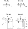
- FIG. 6 illustrates a suitable temperature probe or thermocouple 150.
- the one or more temperature probes can be contained within a temperature probe housing 122 to protect the temperature probes.
- Temperature probe housing 122 can be positioned in place by an upper clamping bracket 130 and a lower clamping bracket 140.
- Upper clamping bracket 130 can be used to hold the temperature probes or temperature probe housing 122 stationary in conjunction with lower clamping bracket 140.
- lower clamping bracket 130 can be attached to fitment heater block assembly 100 using any suitable fastening mechanisms such as bolts 142.
- Upper clamping bracket 130 can be positioned over temperature probe housing 122 and attached to fitment heater block assembly 100 using any suitable fastening mechanisms such as a bolt 136.
- upper clamping bracket 130 and lower clamping bracket 140 can define one or more passages 132 for bolts to attach clamping brackets 130 and 140 securely to fitment heater block assembly 100.
- upper clamping bracket 130 and lower clamping bracket 140 can also define an arced portion 134 so that the temperature probes can fit besides upper clamping bracket 130 and lower clamping bracket 140 as the temperature probes are positioned in fitment heater block 102.
- thermocouple wiring in conventional fill, form and seal devices typically leads to down time of 6 or more hours.
- the use of upper clamping bracket 130 and lower clamping bracket 140 in conjunction with fitment heater block 100 and the temperature probes and heating cartridges have been shown to reduce breaking or failure of standard thermocouple wiring in conventional fill, form and seal devices. This saves operating costs and increases operational efficiency of the fill, form and seal devices by reducing the amount of down time spent repairing the thermocouple.
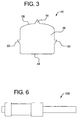
- fitment heater block 102 can include an extended portion 160.
- Extended portion 160 can be in the shape of ring or a bulls-eye.
- the center of the ring can be recessed.
- Extended portion 160 of fitment heater block 102 contacts a side of a film during a fitment placement operation.
- FIGS. 7-14 illustrate various components of a fitment transfer assembly.
- FIG. 7 illustrates a fitment transfer framework or housing 202 for a fitment applicator station 300 shown in FIG. 8 in an example of the present disclosure.
- Fitment applicator station includes an applicator plate 310 and one or more bushings 312 attached to applicator plate 310.
- Bushings 312 can be used to so that applicator plate 310 remains firmly and securely attached to fitment transfer framework or housing 202.
- one or more columns 204 from housing 202 can be positioned through corresponding holes 304 in applicator plate 310 and within bushings 312.
- Bushings 312 can be attached to applicator plate 310 using any suitable fastening mechanisms such as one or more bolts 350.
- An applicator spacer block 314 is used to support a fitment applicator 320 firmly on applicator plate 310.
- Fitment applicator 320 can be attached to applicator spacer block 314 using any suitable fastening mechanisms such as one or more bolts 340.
- Fitment applicator 320 includes an applicator head plate 322.
- Applicator head plate 322 can be attached to fitment applicator 320 by one or more fastening mechanisms such as pins or screws 342.
- an applicator head 324 is attached to applicator head plate 322.
- Applicator head cap 326 is attached to applicator head 324.
- An applicator head washer 328 can be inserted between applicator head cap 326 and applicator head 320 to provide an air-tight seal.
- Applicator head plate 322 can define a passage 332 that can be attached to a vacuum tube that is part of a vacuum assembly (not shown).
- Applicator head cap 326 can be constructed and arranged to match an end of a fitment that will be suctioned into applicator head 324 via the vacuum assembly.
- Applicator 324 can further be attached to a fiber optic device 330 that is used to detector whether a fitment is attached to applicator head 324.
- Fitment indexer 400 transports a fitment 402 from an initial fitment holder or storage device to fitment applicator station 300.
- Fitment indexer includes a vertical positioning stand 410.
- Vertical positioning stand 410 can have any suitable arrangement to provide a solid and stable structural support for fitment indexer 400.
- a horizontal fitment positioning assembly 450 is slidably attached to a vertical guided pneumatic actuator device 420 via a vertical slide assembly 430.
- Horizontal fitment positioning assembly 450 is constructed and arranged to move the fitment axially in a direction that is perpendicular to the movement of vertical slide assembly 430.
- Vertical guided pneumatic actuator device 420 is attached to vertical positioning stand 410.
- Vertical guided pneumatic actuator device 420 can be attached to vertical positioning stand 410 using any suitable fastening mechanisms such as one or more bolts or pins 422.
- Vertical sliding assembly 430 comprises a base or mount that is slidably attached to vertical guided pneumatic actuator device 420.
- Vertical sliding assembly 430 is constructed and arranged to move horizontal fitment positioning assembly 450 up and down along vertical guided pneumatic actuator device 420 via any suitable mechanism such as, for example, a rodless pneumatic cylinder or actuator.
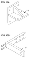
- Horizontal fitment positioning assembly 450 can be attached to vertical sliding assembly 430 via an attachment support 440 (see FIG. 12A ).
- Horizontal fitment positioning assembly 450 includes a guided pneumatic actuator assembly 452 attached to attachment support 440.
- a bracket 454 (see FIG. 12B ) is attached to guided pneumatic actuator assembly 452 that moves via a pneumatic cylinder or actuator.
- Bracket 454 is attached to guided pneumatic actuator assembly 452 using any suitable fastening mechanisms such as one or more bolts or pins 456.
- a vacuum nozzle 462 is attached to an end of bracket 454.
- a pick-up pin nipple 460 is attached to vacuum nozzle 462.
- Vacuum nozzle 462 is constructed and arranged to provide a vacuum through pick-up pin nipple 460.
- Pick-up pin nipple 460 in conjunction with vacuum nozzle 462 to pick up and hold fitment 402 onto the end of pick-up pin nipple 460 as fitment 402 is transported all the way from the fitment storage location to fitment applicator station 300.
- any suitable mounting assembly can be used to hold fitment indexer 400 in place including vertical positioning stand 410.
- the mounting assembly can include any suitable configuration for providing a secure foundation for fitment indexers in embodiments of the present disclosure.
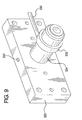
- Feed conveyor system 600 includes a support frame 610.
- a fitment rail assembly 620 is attached to support frame 610 using any suitable fastening mechanisms such as one or more bolts or pins 660.
- Fitment rail assembly 620 can be made of a first elongated rail 622, a second elongated rail 624, a third elongated rail 626, a fourth elongated rail 628 and a rail end guide 630 that are constructed and arranged to hold one or more fitments 632, for example, in a row along the length of fitment rail assembly as shown in FIG. 14 .
- Feed conveyor system 600 also includes a fitment indexing module 650 attached to support frame 610.
- Fitment indexing module 650 can be attached to support frame 610 via a guided pneumatic actuator mounting plate 652.
- Fitment indexing module 650 is also attached to an end of fitment rail assembly 620 at or near rail end guide 630.
- Fitment indexing module 650 includes an actuator plate 654 defining a curved portion 658 for partially housing a fitment.
- Fitment indexing module 650 includes a pneumatic actuator 656 that is constructed and arranged to move actuator plate 654 up and down or towards and away from fitment indexing module 650.
- fitment indexing module 650 enables a fitment to be exposed to and picked up by pick-up pin nipple 460 and vacuum nozzle 462 of fitment indexer 400.
- fitment rail assembly 620 is constructed and arranged at an angle from support frame 610 in a manner that allows the series of fitments 632 contained within fitment rail assembly 620 to move by gravity from the end that is attached to support frame 610 towards the end having rail end guide 630.
- fitment rail assembly 620 comprises an air or gas outlet 634 that expels air into fitments 632 to assist in pushing fitments 632 toward rail end guide 630.
- pneumatic actuator 656 moves actuator plate 654 up so that curved portion 658 is directly in the pathway of the series of fitments 632. One fitment slides into curved portion 658. Pneumatic actuator 656 then moves actuator plate down 654 so that fitment 632 aligns with pick-up pin nipple 460 of fitment indexer 400. Fitment indexer 400 then transports fitment 632 to fitment applicator station 300 where it can be placed onto a container.
- a fitment indexer 400 comprises a vertical positioning stand 410 comprising a vertical sliding assembly 430; and a horizontal fitment positioning assembly 450 attached to the vertical sliding assembly 430.
- the vertical sliding assembly 430 can be slidably attached to a vertical guided pneumatic actuator device 420 attached to the vertical positioning stand 410.
- the horizontal fitment positioning assembly 450 can comprise a guided pneumatic actuator assembly 452 attached to a bracket 454, the guided pneumatic actuator assembly 452 constructed and arranged to move the bracket 454 in a direction that is approximately perpendicular to a direction of movement by the vertical sliding assembly 430.
- the vertical guided pneumatic actuator device 420 can comprise a rodless pneumatic actuator, the vertical sliding assembly 430 attached to the rodless pneumatic actuator; and an attachment support 440 attached to the vertical sliding assembly 430.
- a vertical guided pneumatic actuator device 420 comprises a rodless pneumatic actuator; a vertical sliding assembly 430 attached to the rodless pneumatic actuator; and an attachment support 440 attached to the vertical sliding assembly 430.
- a horizontal fitment positioning assembly 450 comprises a guided pneumatic actuator assembly 452 comprising a pneumatic actuator; a bracket 454 attached to the guided pneumatic actuator assembly 452; a vacuum nozzle 462 attached to the bracket 454; and a pick-up pin nozzle 460 attached to the vacuum nozzle 462.
- the pickup pin nozzle 462 can comprise a tapered end portion.
- the pick-up pin nozzle 462 can comprise an end portion having a circumferential flange.
- the circumferential flange can have at least one flat edge.
- the bracket 454 can be in the shape of an L.
- a feed conveyor system 600 can comprise a support frame 610; a fitment rail assembly 620 attached to the support frame 610; and a fitment indexing module 650 attached to the support frame 610.
- the fitment rail assembly 620 can comprise a first elongated rail 622, a second elongated rail 624, a third elongated rail 626, a fourth elongated rail 628 and a rail end guide 630 that is constructed and arranged to hold a plurality of fitments 632.
- the fitment rail assembly 620 can be angled away from the support frame 610 and attached to the fitment indexing module 650 at an end of the fitment rail assembly 620 located farthest from the support frame 610.
- the fitment indexing module 650 can be attached to the support frame 610 via a guided pneumatic actuator mounting plate 652.
- the fitment indexing module 650 can comprise a pneumatic actuator 656 and an actuator plate 654 attached to the pneumatic actuator 656.
- the pneumatic actuator 656 can be constructed and arranged to move the actuator plate 654 towards and away from the pneumatic actuator 656.
- the actuator plate 654 can define a curved portion 658 that is constructed and arranged to receive a fitment 632.
- a fitment indexing module 650 can comprise a pneumatic actuator 656; and an actuator plate 654 attached to the pneumatic actuator 656, the pneumatic actuator 656 constructed and arranged to move the actuator plate 654 towards and away from the pneumatic actuator 656.
- the actuator plate 654 can define a curved portion 658 that is constructed and arranged to receive a fitment 632.
- a method of transporting a fitment 632 can comprise: providing a feed conveyor system 600 comprising a support frame 610, a fitment rail assembly 620 attached to the support frame 610, and a fitment indexing module 650 attached to the support frame 610, the fitment indexing module 650 comprising a pneumatic actuator 656; and an actuator plate 654 attached to the pneumatic actuator 656; adding at least one fitment 632 to the fitment rail assembly 620; feeding the fitment 632 into the actuator plate 654 of the fitment indexing module 650; and lowering the actuator plate 654 containing the fitment 632.
- the method can further comprise placing the fitment 632 into a pickup pin nipple 460 of a fitment indexer 400.
- the pneumatic actuator 656 can be constructed and arranged to move the actuator plate 654 towards and away from the pneumatic actuator 656.
- the actuator plate 654 can define a curved portion 658 that is constructed and arranged to receive a fitment 632.
- a method of applying a fitment 632 to a container can comprise: providing a feed conveyor system 600 comprising a support frame 610, a fitment rail assembly 620 attached to the support frame 610, and a fitment indexing module 650 attached to the support frame 610, the fitment indexing module 650 comprising a pneumatic actuator 656; and an actuator plate 654 attached to the pneumatic actuator 656; adding at least one fitment 632 to the fitment rail assembly 620; feeding the fitment 632 into the actuator plate 654 of the fitment indexing module 650; lowering the actuator plate 654 containing the fitment 632; placing the fitment 632 into a pick-up pin nipple 460 of a fitment indexer 400; and inserting the fitment 632 onto a container using the fitment indexer 400.
- the pneumatic actuator 656 can be constructed and arranged to move the actuator plate 654 towards and away from the pneumatic actuator 656.
- the actuator plate 654 can define a curved portion 658 that is constructed and arranged to receive a fitment 632.
- the fitment indexer 400 can comprise a vertical positioning stand 410 comprising a vertical sliding assembly 430 and a horizontal fitment positioning assembly 450 attached to the vertical sliding assembly 430.
- the vertical sliding assembly 430 can be slidably attached to a vertical guided pneumatic actuator device 420 attached to the vertical positioning stand 410.
- the horizontal fitment positioning assembly 450 can comprise a guided pneumatic actuator assembly 452 attached to a bracket 454, the guided pneumatic actuator assembly 452 can be constructed and arranged to move the bracket 454 in a direction that is approximately perpendicular to a direction of movement by the vertical sliding assembly 430.
- the vertical guided pneumatic actuator device 420 can comprise a rodless pneumatic actuator, the vertical sliding assembly 430 can be attached to the rodless pneumatic actuator; and an attachment support 440 attached to the vertical sliding assembly 430.
Landscapes
- Engineering & Computer Science (AREA)
- Mechanical Engineering (AREA)
- Physics & Mathematics (AREA)
- Fluid Mechanics (AREA)
- General Engineering & Computer Science (AREA)
- Making Paper Articles (AREA)
- Closing Of Containers (AREA)
- Lining Or Joining Of Plastics Or The Like (AREA)
- Auxiliary Devices For And Details Of Packaging Control (AREA)
- Package Closures (AREA)
- Filling Of Jars Or Cans And Processes For Cleaning And Sealing Jars (AREA)
- Biological Treatment Of Waste Water (AREA)
- Bedding Items (AREA)
- Medicines Containing Plant Substances (AREA)
Claims (3)
- Formstück-Übergabevorrichtung (400), umfassend:einen vertikalen Positionierungsständer (410), der eine vertikale Schiebebaugruppe (430) und eine horizontale, an der vertikalen Schiebebaugruppe (430) befestigte Formstückpositionierbaugruppe (450) umfasst,wobei die vertikale Schiebebaugruppe (430) verschiebbar an einer vertikalen, geführten, pneumatischen Betätigungsvorrichtung (420) befestigt ist, die an dem vertikalen Positionierungsständer (410) befestigt ist,wobei die vertikale, geführte, pneumatische Betätigungsvorrichtung (420) ein stangenloses, pneumatisches Stellglied umfasst, die vertikale Schiebebaugruppe (430) an dem stangenlosen, pneumatischen Stellglied befestigt ist unddie horizontale Formstückpositionierbaugruppe (450) über eine Befestigungsstütze (440) an der vertikalen Schiebebaugruppe (430) befestigt ist,wobei die Befestigungsstütze (440) zwei Platten umfasst, wobei jede Platte eine obere Oberfläche, untere Oberfläche und vier Seitenoberflächen umfasst und die Seitenoberflächen die Ausdehnung der oberen und unteren Oberfläche beschränken, wobei eine der zwei Platten senkrecht an der anderen der zwei Platten befestigt ist und die obere und untere Oberfläche, die horizontale Oberflächen sind, der einen Platte innerhalb flacher Ebenen bereitgestellt sind, die die obere und untere Oberfläche, die vertikale Oberflächen sind, der anderen Platte schneiden,wobei die horizontale Formstückpositionierbaugruppe (450) an der horizontalen unteren Oberfläche der einen Platte befestigt ist, die einen rechten Winkel mit der anderen Platte einschließt, und die vertikale Schiebebaugruppe (430) an der vertikalen unteren Oberfläche der anderen Platte befestigt ist, die von der einen Platte weg zeigt.
- Formstück-Übergabevorrichtung (400) nach Anspruch 1, wobei die horizontale Formstückpositionierbaugruppe (450) eine geführte pneumatische Betätigungsbaugruppe (452) umfasst, die an einer Halterung (454) befestigt ist, wobei die geführte, pneumatische Betätigungsbaugruppe (452) so konstruiert und angeordnet ist, dass sie die Halterung (454) in eine Richtung bewegt, die ungefähr senkrecht zu einer Bewegungsrichtung durch die vertikale Schiebebaugruppe (430) liegt.
- Vertikale, geführte, pneumatische Betätigungsvorrichtung (420), umfassend:ein stangenloses, pneumatisches Stellglied;eine vertikale Schiebebaugruppe (430), die an dem stangenlosen, pneumatischen Stellglied befestigt ist; und eine Befestigungsstütze (440), die an der vertikalen Schiebebaugruppe (430) befestigt ist, wobei die Befestigungsstütze (440) zwei Platten umfasst, wobei jede Platte eine obere Oberfläche, untere Oberfläche und vier Seitenoberflächen umfasst und die Seitenoberflächen die Ausdehnung der oberen und unteren Oberfläche beschränken, wobei eine der zwei Platten senkrecht an der anderen der zwei Platten befestigt ist und die obere und untere Oberfläche, die horizontale Oberflächen sind, der einen Platte innerhalb flacher Ebenen bereitgestellt sind, die die obere und untere Oberfläche, die vertikale Oberflächen sind, der anderen Platte schneiden,wobei die vertikale Schiebebaugruppe (430) an der vertikalen unteren Oberfläche der anderen Platte, die von der einen Platte weg zeigt, befestigt ist.
Applications Claiming Priority (2)
| Application Number | Priority Date | Filing Date | Title |
|---|---|---|---|
| US16360509P | 2009-03-26 | 2009-03-26 | |
| EP10716426.1A EP2411291B1 (de) | 2009-03-26 | 2010-03-24 | Ausgiesserzuführvorrichtung für eine beutelfüllvorrichtung |
Related Parent Applications (2)
| Application Number | Title | Priority Date | Filing Date |
|---|---|---|---|
| EP10716426.1 Division | 2010-03-24 | ||
| EP10716426.1A Division EP2411291B1 (de) | 2009-03-26 | 2010-03-24 | Ausgiesserzuführvorrichtung für eine beutelfüllvorrichtung |
Publications (2)
| Publication Number | Publication Date |
|---|---|
| EP2644519A1 EP2644519A1 (de) | 2013-10-02 |
| EP2644519B1 true EP2644519B1 (de) | 2016-07-27 |
Family
ID=42224560
Family Applications (2)
| Application Number | Title | Priority Date | Filing Date |
|---|---|---|---|
| EP13173907.0A Active EP2644519B1 (de) | 2009-03-26 | 2010-03-24 | Hin- und herbewegliche formstück-übergabevorrichtung für eine beutelfüllmaschine |
| EP10716426.1A Active EP2411291B1 (de) | 2009-03-26 | 2010-03-24 | Ausgiesserzuführvorrichtung für eine beutelfüllvorrichtung |
Family Applications After (1)
| Application Number | Title | Priority Date | Filing Date |
|---|---|---|---|
| EP10716426.1A Active EP2411291B1 (de) | 2009-03-26 | 2010-03-24 | Ausgiesserzuführvorrichtung für eine beutelfüllvorrichtung |
Country Status (13)
| Country | Link |
|---|---|
| US (1) | US9061782B2 (de) |
| EP (2) | EP2644519B1 (de) |
| JP (1) | JP5650715B2 (de) |
| CN (1) | CN102365209B (de) |
| AU (1) | AU2010230042A1 (de) |
| CA (1) | CA2755345A1 (de) |
| DK (1) | DK2644519T3 (de) |
| ES (2) | ES2430355T3 (de) |
| MX (1) | MX2011009910A (de) |
| RU (1) | RU2011143145A (de) |
| SG (1) | SG173912A1 (de) |
| WO (1) | WO2010111327A1 (de) |
| ZA (1) | ZA201107808B (de) |
Families Citing this family (4)
| Publication number | Priority date | Publication date | Assignee | Title |
|---|---|---|---|---|
| SG173912A1 (en) | 2009-03-26 | 2011-10-28 | Nestec Sa | A fitment indexer for a pouch filler |
| JP2011228388A (ja) * | 2010-04-16 | 2011-11-10 | Honda Motor Co Ltd | 補助基板接合構造 |
| CN102363449A (zh) * | 2011-10-31 | 2012-02-29 | 菱翔光电(苏州)有限公司 | 薄膜切割机 |
| USD867398S1 (en) * | 2015-12-18 | 2019-11-19 | Smc Corporation | Fluid pressure cylinder with table |
Citations (1)
| Publication number | Priority date | Publication date | Assignee | Title |
|---|---|---|---|---|
| EP0069199B1 (de) * | 1981-06-25 | 1984-10-31 | PROMA Produkt- und Marketing-Gesellschaft m.b.H. | Druckmittelzylinder |
Family Cites Families (21)
| Publication number | Priority date | Publication date | Assignee | Title |
|---|---|---|---|---|
| AU559751B2 (en) | 1982-10-18 | 1987-03-19 | Unitika Ltd. | Filling bags with cap bodies |
| JPH0633450B2 (ja) | 1987-11-09 | 1994-05-02 | 日電アネルバ株式会社 | イオンビームデポジション方法 |
| JPH0366735A (ja) | 1989-08-04 | 1991-03-22 | Tonen Chem Corp | 多層成形品用熱可塑性樹脂組成物 |
| JPH07280Y2 (ja) * | 1989-10-31 | 1995-01-11 | 日本製紙株式会社 | 容器に対する注出口部挿入装置 |
| JPH0736740Y2 (ja) * | 1991-05-16 | 1995-08-23 | 凸版印刷株式会社 | 紙製容器の注出口仮着装置 |
| DE4334681C2 (de) | 1993-10-12 | 1995-09-28 | Norgren Martonair Gmbh | Bewegungseinheit zur Erzeugung einer Linearbewegung |
| JP3328037B2 (ja) | 1993-11-10 | 2002-09-24 | 日本製紙株式会社 | 容器に取付けられる注出口部の取出し方法と取出し装置 |
| US5473857A (en) * | 1993-11-16 | 1995-12-12 | International Paper Company | System integration for hot melt sealing of fitments in-line with form/fill/seal machine |
| US5601669A (en) | 1994-10-04 | 1997-02-11 | Portola Packaging, Inc. | Apparatus and method for attaching fitments to cartons |
| CN2358038Y (zh) * | 1998-05-08 | 2000-01-12 | 杰宏铁工厂股份有限公司 | 送盖机 |
| US6145275A (en) * | 1998-06-11 | 2000-11-14 | Tetra Laval Holdings & Finance, Sa | Apparatus for applying a fitment to pre-formed carton at the infeed to a packaging machine |
| JP4639479B2 (ja) * | 2001-01-26 | 2011-02-23 | 四国化工機株式会社 | 容器口栓取付装置 |
| DE10130816A1 (de) | 2001-06-26 | 2003-01-02 | Manfred Boening | Kolbenstangenloser Lineartrieb - für reversible Bewegung durch Rundriemen für Pneumatik und Fluid |
| JP2003053859A (ja) * | 2001-08-20 | 2003-02-26 | Toppan Printing Co Ltd | 口栓挿入装置 |
| JP2003278714A (ja) | 2002-03-26 | 2003-10-02 | Sakai Giken:Kk | ベルト式ロッドレスシリンダー |
| DE10220058A1 (de) | 2002-05-04 | 2003-11-20 | Sig Combibloc Gmbh | Verfahren und Vorrichtung zum Applizieren von Ausgießelementen an Packungen und danach hergestellte Packungen |
| US7032363B1 (en) * | 2004-10-19 | 2006-04-25 | Tetra Laval Holdings & Finance, Sa | Linear fitment applicator and method |
| WO2006054067A1 (en) | 2004-11-16 | 2006-05-26 | Elopak Systems Ag | Apparatus and method |
| ITTO20050914A1 (it) * | 2005-12-29 | 2007-06-30 | Arol Spa | Dispositivo di alimentazione di tappi con buffer integrato |
| CN2923655Y (zh) * | 2006-07-24 | 2007-07-18 | 厉善红 | 理盖机 |
| SG173912A1 (en) | 2009-03-26 | 2011-10-28 | Nestec Sa | A fitment indexer for a pouch filler |
-
2010
- 2010-03-24 SG SG2011063518A patent/SG173912A1/en unknown
- 2010-03-24 ES ES10716426T patent/ES2430355T3/es active Active
- 2010-03-24 JP JP2012502187A patent/JP5650715B2/ja active Active
- 2010-03-24 US US13/257,006 patent/US9061782B2/en active Active
- 2010-03-24 RU RU2011143145/13A patent/RU2011143145A/ru not_active Application Discontinuation
- 2010-03-24 CN CN201080013532.9A patent/CN102365209B/zh active Active
- 2010-03-24 EP EP13173907.0A patent/EP2644519B1/de active Active
- 2010-03-24 DK DK13173907.0T patent/DK2644519T3/en active
- 2010-03-24 AU AU2010230042A patent/AU2010230042A1/en not_active Abandoned
- 2010-03-24 ES ES13173907.0T patent/ES2593603T3/es active Active
- 2010-03-24 WO PCT/US2010/028404 patent/WO2010111327A1/en not_active Ceased
- 2010-03-24 MX MX2011009910A patent/MX2011009910A/es not_active Application Discontinuation
- 2010-03-24 CA CA2755345A patent/CA2755345A1/en not_active Abandoned
- 2010-03-24 EP EP10716426.1A patent/EP2411291B1/de active Active
-
2011
- 2011-10-25 ZA ZA2011/07808A patent/ZA201107808B/en unknown
Patent Citations (1)
| Publication number | Priority date | Publication date | Assignee | Title |
|---|---|---|---|---|
| EP0069199B1 (de) * | 1981-06-25 | 1984-10-31 | PROMA Produkt- und Marketing-Gesellschaft m.b.H. | Druckmittelzylinder |
Also Published As
| Publication number | Publication date |
|---|---|
| EP2411291B1 (de) | 2013-07-10 |
| CA2755345A1 (en) | 2010-09-30 |
| JP2012521933A (ja) | 2012-09-20 |
| CN102365209A (zh) | 2012-02-29 |
| US9061782B2 (en) | 2015-06-23 |
| MX2011009910A (es) | 2011-09-30 |
| WO2010111327A1 (en) | 2010-09-30 |
| ES2430355T3 (es) | 2013-11-20 |
| HK1164813A1 (en) | 2012-09-28 |
| ZA201107808B (en) | 2013-03-27 |
| DK2644519T3 (en) | 2016-09-19 |
| JP5650715B2 (ja) | 2015-01-07 |
| RU2011143145A (ru) | 2013-05-10 |
| AU2010230042A1 (en) | 2011-09-29 |
| ES2593603T3 (es) | 2016-12-12 |
| SG173912A1 (en) | 2011-10-28 |
| US20120122643A1 (en) | 2012-05-17 |
| CN102365209B (zh) | 2014-11-26 |
| EP2644519A1 (de) | 2013-10-02 |
| EP2411291A1 (de) | 2012-02-01 |
Similar Documents
| Publication | Publication Date | Title |
|---|---|---|
| EP2411290B1 (de) | Heizanordnung für ein anschlussstück und verfahren zum anbringen eines anschlussstücks | |
| CN209127068U (zh) | 一种试剂盒全自动灌装和封闭生产线 | |
| EP2644519B1 (de) | Hin- und herbewegliche formstück-übergabevorrichtung für eine beutelfüllmaschine | |
| CN112777048B (zh) | 平口袋封口装置 | |
| CN109178490B (zh) | 入袋平台及包膜设备 | |
| CN108688902B (zh) | 包装系统 | |
| KR100898779B1 (ko) | 용기 밀봉장치 | |
| CN110844192B (zh) | 一种贴标制袋包装生产线 | |
| CN217864874U (zh) | 液体灌装封口机 | |
| HK1176916A (en) | A jaw support for a pouch filler | |
| HK1164813B (en) | A fitment indexer for a pouch filler | |
| CN222682868U (zh) | 一种薯片包装用消除移位的热压封口装置 | |
| CN119954085B (zh) | 一种灌装热封转盘机 | |
| CN218662677U (zh) | 一种包装封口装置 | |
| JPS58125426A (ja) | 自動袋詰機械における開袋開口装置 |
Legal Events
| Date | Code | Title | Description |
|---|---|---|---|
| AC | Divisional application: reference to earlier application |
Ref document number: 2411291 Country of ref document: EP Kind code of ref document: P |
|
| AK | Designated contracting states |
Kind code of ref document: A1 Designated state(s): AT BE BG CH CY CZ DE DK EE ES FI FR GB GR HR HU IE IS IT LI LT LU LV MC MK MT NL NO PL PT RO SE SI SK SM TR |
|
| PUAI | Public reference made under article 153(3) epc to a published international application that has entered the european phase |
Free format text: ORIGINAL CODE: 0009012 |
|
| 17P | Request for examination filed |
Effective date: 20140227 |
|
| RBV | Designated contracting states (corrected) |
Designated state(s): AT BE BG CH CY CZ DE DK EE ES FI FR GB GR HR HU IE IS IT LI LT LU LV MC MK MT NL NO PL PT RO SE SI SK SM TR |
|
| 17Q | First examination report despatched |
Effective date: 20140402 |
|
| GRAP | Despatch of communication of intention to grant a patent |
Free format text: ORIGINAL CODE: EPIDOSNIGR1 |
|
| RIC1 | Information provided on ipc code assigned before grant |
Ipc: B65B 61/18 20060101AFI20160204BHEP Ipc: B31B 1/84 20060101ALI20160204BHEP Ipc: F15B 15/08 20060101ALI20160204BHEP Ipc: F15B 15/14 20060101ALN20160204BHEP |
|
| RIC1 | Information provided on ipc code assigned before grant |
Ipc: F15B 15/14 20060101ALN20160205BHEP Ipc: B31B 1/84 20060101ALI20160205BHEP Ipc: F15B 15/08 20060101ALI20160205BHEP Ipc: B65B 61/18 20060101AFI20160205BHEP |
|
| INTG | Intention to grant announced |
Effective date: 20160223 |
|
| RIN1 | Information on inventor provided before grant (corrected) |
Inventor name: GYNNILD, ROBERT |
|
| GRAS | Grant fee paid |
Free format text: ORIGINAL CODE: EPIDOSNIGR3 |
|
| GRAA | (expected) grant |
Free format text: ORIGINAL CODE: 0009210 |
|
| AC | Divisional application: reference to earlier application |
Ref document number: 2411291 Country of ref document: EP Kind code of ref document: P |
|
| AK | Designated contracting states |
Kind code of ref document: B1 Designated state(s): AT BE BG CH CY CZ DE DK EE ES FI FR GB GR HR HU IE IS IT LI LT LU LV MC MK MT NL NO PL PT RO SE SI SK SM TR |
|
| REG | Reference to a national code |
Ref country code: GB Ref legal event code: FG4D |
|
| REG | Reference to a national code |
Ref country code: CH Ref legal event code: EP |
|
| REG | Reference to a national code |
Ref country code: AT Ref legal event code: REF Ref document number: 815580 Country of ref document: AT Kind code of ref document: T Effective date: 20160815 |
|
| REG | Reference to a national code |
Ref country code: IE Ref legal event code: FG4D |
|
| REG | Reference to a national code |
Ref country code: DE Ref legal event code: R096 Ref document number: 602010035131 Country of ref document: DE |
|
| REG | Reference to a national code |
Ref country code: DK Ref legal event code: T3 Effective date: 20160913 |
|
| REG | Reference to a national code |
Ref country code: NL Ref legal event code: FP |
|
| REG | Reference to a national code |
Ref country code: SE Ref legal event code: TRGR |
|
| REG | Reference to a national code |
Ref country code: LT Ref legal event code: MG4D |
|
| REG | Reference to a national code |
Ref country code: ES Ref legal event code: FG2A Ref document number: 2593603 Country of ref document: ES Kind code of ref document: T3 Effective date: 20161212 |
|
| PG25 | Lapsed in a contracting state [announced via postgrant information from national office to epo] |
Ref country code: NO Free format text: LAPSE BECAUSE OF FAILURE TO SUBMIT A TRANSLATION OF THE DESCRIPTION OR TO PAY THE FEE WITHIN THE PRESCRIBED TIME-LIMIT Effective date: 20161027 Ref country code: HR Free format text: LAPSE BECAUSE OF FAILURE TO SUBMIT A TRANSLATION OF THE DESCRIPTION OR TO PAY THE FEE WITHIN THE PRESCRIBED TIME-LIMIT Effective date: 20160727 Ref country code: LT Free format text: LAPSE BECAUSE OF FAILURE TO SUBMIT A TRANSLATION OF THE DESCRIPTION OR TO PAY THE FEE WITHIN THE PRESCRIBED TIME-LIMIT Effective date: 20160727 Ref country code: IS Free format text: LAPSE BECAUSE OF FAILURE TO SUBMIT A TRANSLATION OF THE DESCRIPTION OR TO PAY THE FEE WITHIN THE PRESCRIBED TIME-LIMIT Effective date: 20161127 |
|
| REG | Reference to a national code |
Ref country code: FR Ref legal event code: PLFP Year of fee payment: 8 |
|
| PG25 | Lapsed in a contracting state [announced via postgrant information from national office to epo] |
Ref country code: BE Free format text: LAPSE BECAUSE OF FAILURE TO SUBMIT A TRANSLATION OF THE DESCRIPTION OR TO PAY THE FEE WITHIN THE PRESCRIBED TIME-LIMIT Effective date: 20160727 Ref country code: GR Free format text: LAPSE BECAUSE OF FAILURE TO SUBMIT A TRANSLATION OF THE DESCRIPTION OR TO PAY THE FEE WITHIN THE PRESCRIBED TIME-LIMIT Effective date: 20161028 Ref country code: PT Free format text: LAPSE BECAUSE OF FAILURE TO SUBMIT A TRANSLATION OF THE DESCRIPTION OR TO PAY THE FEE WITHIN THE PRESCRIBED TIME-LIMIT Effective date: 20161128 Ref country code: PL Free format text: LAPSE BECAUSE OF FAILURE TO SUBMIT A TRANSLATION OF THE DESCRIPTION OR TO PAY THE FEE WITHIN THE PRESCRIBED TIME-LIMIT Effective date: 20160727 Ref country code: LV Free format text: LAPSE BECAUSE OF FAILURE TO SUBMIT A TRANSLATION OF THE DESCRIPTION OR TO PAY THE FEE WITHIN THE PRESCRIBED TIME-LIMIT Effective date: 20160727 |
|
| PG25 | Lapsed in a contracting state [announced via postgrant information from national office to epo] |
Ref country code: EE Free format text: LAPSE BECAUSE OF FAILURE TO SUBMIT A TRANSLATION OF THE DESCRIPTION OR TO PAY THE FEE WITHIN THE PRESCRIBED TIME-LIMIT Effective date: 20160727 Ref country code: RO Free format text: LAPSE BECAUSE OF FAILURE TO SUBMIT A TRANSLATION OF THE DESCRIPTION OR TO PAY THE FEE WITHIN THE PRESCRIBED TIME-LIMIT Effective date: 20160727 |
|
| REG | Reference to a national code |
Ref country code: DE Ref legal event code: R097 Ref document number: 602010035131 Country of ref document: DE |
|
| PG25 | Lapsed in a contracting state [announced via postgrant information from national office to epo] |
Ref country code: CZ Free format text: LAPSE BECAUSE OF FAILURE TO SUBMIT A TRANSLATION OF THE DESCRIPTION OR TO PAY THE FEE WITHIN THE PRESCRIBED TIME-LIMIT Effective date: 20160727 Ref country code: SM Free format text: LAPSE BECAUSE OF FAILURE TO SUBMIT A TRANSLATION OF THE DESCRIPTION OR TO PAY THE FEE WITHIN THE PRESCRIBED TIME-LIMIT Effective date: 20160727 Ref country code: BG Free format text: LAPSE BECAUSE OF FAILURE TO SUBMIT A TRANSLATION OF THE DESCRIPTION OR TO PAY THE FEE WITHIN THE PRESCRIBED TIME-LIMIT Effective date: 20161027 Ref country code: SK Free format text: LAPSE BECAUSE OF FAILURE TO SUBMIT A TRANSLATION OF THE DESCRIPTION OR TO PAY THE FEE WITHIN THE PRESCRIBED TIME-LIMIT Effective date: 20160727 |
|
| PLBE | No opposition filed within time limit |
Free format text: ORIGINAL CODE: 0009261 |
|
| STAA | Information on the status of an ep patent application or granted ep patent |
Free format text: STATUS: NO OPPOSITION FILED WITHIN TIME LIMIT |
|
| 26N | No opposition filed |
Effective date: 20170502 |
|
| PG25 | Lapsed in a contracting state [announced via postgrant information from national office to epo] |
Ref country code: SI Free format text: LAPSE BECAUSE OF FAILURE TO SUBMIT A TRANSLATION OF THE DESCRIPTION OR TO PAY THE FEE WITHIN THE PRESCRIBED TIME-LIMIT Effective date: 20160727 |
|
| PG25 | Lapsed in a contracting state [announced via postgrant information from national office to epo] |
Ref country code: MC Free format text: LAPSE BECAUSE OF FAILURE TO SUBMIT A TRANSLATION OF THE DESCRIPTION OR TO PAY THE FEE WITHIN THE PRESCRIBED TIME-LIMIT Effective date: 20160727 |
|
| REG | Reference to a national code |
Ref country code: IE Ref legal event code: MM4A |
|
| PG25 | Lapsed in a contracting state [announced via postgrant information from national office to epo] |
Ref country code: LU Free format text: LAPSE BECAUSE OF NON-PAYMENT OF DUE FEES Effective date: 20170324 |
|
| REG | Reference to a national code |
Ref country code: FR Ref legal event code: PLFP Year of fee payment: 9 |
|
| PG25 | Lapsed in a contracting state [announced via postgrant information from national office to epo] |
Ref country code: IE Free format text: LAPSE BECAUSE OF NON-PAYMENT OF DUE FEES Effective date: 20170324 |
|
| PG25 | Lapsed in a contracting state [announced via postgrant information from national office to epo] |
Ref country code: MT Free format text: LAPSE BECAUSE OF NON-PAYMENT OF DUE FEES Effective date: 20170324 |
|
| REG | Reference to a national code |
Ref country code: AT Ref legal event code: UEP Ref document number: 815580 Country of ref document: AT Kind code of ref document: T Effective date: 20160727 |
|
| PGFP | Annual fee paid to national office [announced via postgrant information from national office to epo] |
Ref country code: CH Payment date: 20190314 Year of fee payment: 10 |
|
| PGFP | Annual fee paid to national office [announced via postgrant information from national office to epo] |
Ref country code: SE Payment date: 20190311 Year of fee payment: 10 Ref country code: AT Payment date: 20190226 Year of fee payment: 10 Ref country code: DK Payment date: 20190312 Year of fee payment: 10 Ref country code: NL Payment date: 20190313 Year of fee payment: 10 |
|
| PG25 | Lapsed in a contracting state [announced via postgrant information from national office to epo] |
Ref country code: HU Free format text: LAPSE BECAUSE OF FAILURE TO SUBMIT A TRANSLATION OF THE DESCRIPTION OR TO PAY THE FEE WITHIN THE PRESCRIBED TIME-LIMIT; INVALID AB INITIO Effective date: 20100324 |
|
| REG | Reference to a national code |
Ref country code: NL Ref legal event code: PD Owner name: SOCIETE DES PRODUITS NESTLE S.A.; CH Free format text: DETAILS ASSIGNMENT: CHANGE OF OWNER(S), MERGE; FORMER OWNER NAME: NESTEC S.A. Effective date: 20190620 |
|
| REG | Reference to a national code |
Ref country code: CH Ref legal event code: PFUS Owner name: SOCIETE DES PRODUITS NESTLE S.A., CH Free format text: FORMER OWNER: NESTEC S.A., CH |
|
| REG | Reference to a national code |
Ref country code: GB Ref legal event code: 732E Free format text: REGISTERED BETWEEN 20190801 AND 20190807 |
|
| REG | Reference to a national code |
Ref country code: ES Ref legal event code: PC2A Owner name: SOCIETE DES PRODUITS NESTLE S.A. Effective date: 20190930 |
|
| REG | Reference to a national code |
Ref country code: AT Ref legal event code: PC Ref document number: 815580 Country of ref document: AT Kind code of ref document: T Owner name: SOCIETE DES PRODUITS NESTLE S.A., CH Effective date: 20190909 |
|
| PG25 | Lapsed in a contracting state [announced via postgrant information from national office to epo] |
Ref country code: CY Free format text: LAPSE BECAUSE OF NON-PAYMENT OF DUE FEES Effective date: 20160727 |
|
| PG25 | Lapsed in a contracting state [announced via postgrant information from national office to epo] |
Ref country code: MK Free format text: LAPSE BECAUSE OF FAILURE TO SUBMIT A TRANSLATION OF THE DESCRIPTION OR TO PAY THE FEE WITHIN THE PRESCRIBED TIME-LIMIT Effective date: 20160727 |
|
| REG | Reference to a national code |
Ref country code: DE Ref legal event code: R082 Ref document number: 602010035131 Country of ref document: DE Representative=s name: MITSCHERLICH, PATENT- UND RECHTSANWAELTE PARTM, DE Ref country code: DE Ref legal event code: R081 Ref document number: 602010035131 Country of ref document: DE Owner name: SOCIETE DES PRODUITS NESTLE S.A., CH Free format text: FORMER OWNER: NESTEC S.A., VEVEY, CH |
|
| REG | Reference to a national code |
Ref country code: FI Ref legal event code: MAE |
|
| PG25 | Lapsed in a contracting state [announced via postgrant information from national office to epo] |
Ref country code: FI Free format text: LAPSE BECAUSE OF NON-PAYMENT OF DUE FEES Effective date: 20200324 |
|
| REG | Reference to a national code |
Ref country code: CH Ref legal event code: PL |
|
| REG | Reference to a national code |
Ref country code: DK Ref legal event code: EBP Effective date: 20200331 |
|
| REG | Reference to a national code |
Ref country code: NL Ref legal event code: MM Effective date: 20200401 |
|
| REG | Reference to a national code |
Ref country code: AT Ref legal event code: MM01 Ref document number: 815580 Country of ref document: AT Kind code of ref document: T Effective date: 20200324 |
|
| PG25 | Lapsed in a contracting state [announced via postgrant information from national office to epo] |
Ref country code: NL Free format text: LAPSE BECAUSE OF NON-PAYMENT OF DUE FEES Effective date: 20200401 |
|
| PG25 | Lapsed in a contracting state [announced via postgrant information from national office to epo] |
Ref country code: CH Free format text: LAPSE BECAUSE OF NON-PAYMENT OF DUE FEES Effective date: 20200331 Ref country code: LI Free format text: LAPSE BECAUSE OF NON-PAYMENT OF DUE FEES Effective date: 20200331 Ref country code: AT Free format text: LAPSE BECAUSE OF NON-PAYMENT OF DUE FEES Effective date: 20200324 Ref country code: SE Free format text: LAPSE BECAUSE OF NON-PAYMENT OF DUE FEES Effective date: 20200325 |
|
| PG25 | Lapsed in a contracting state [announced via postgrant information from national office to epo] |
Ref country code: DK Free format text: LAPSE BECAUSE OF NON-PAYMENT OF DUE FEES Effective date: 20200331 |
|
| PG25 | Lapsed in a contracting state [announced via postgrant information from national office to epo] |
Ref country code: IT Free format text: LAPSE BECAUSE OF NON-PAYMENT OF DUE FEES Effective date: 20200324 |
|
| PG25 | Lapsed in a contracting state [announced via postgrant information from national office to epo] |
Ref country code: TR Free format text: LAPSE BECAUSE OF NON-PAYMENT OF DUE FEES Effective date: 20200324 |
|
| P01 | Opt-out of the competence of the unified patent court (upc) registered |
Effective date: 20230527 |
|
| PGFP | Annual fee paid to national office [announced via postgrant information from national office to epo] |
Ref country code: ES Payment date: 20250410 Year of fee payment: 16 |
|
| PGFP | Annual fee paid to national office [announced via postgrant information from national office to epo] |
Ref country code: GB Payment date: 20260202 Year of fee payment: 17 |
|
| PGFP | Annual fee paid to national office [announced via postgrant information from national office to epo] |
Ref country code: DE Payment date: 20260204 Year of fee payment: 17 |
|
| PGFP | Annual fee paid to national office [announced via postgrant information from national office to epo] |
Ref country code: FR Payment date: 20260209 Year of fee payment: 17 |