EP2647603A2 - Dispositif destiné à la fabrication de corps creux à partir d'un bain de verre - Google Patents
Dispositif destiné à la fabrication de corps creux à partir d'un bain de verre Download PDFInfo
- Publication number
- EP2647603A2 EP2647603A2 EP13160570.1A EP13160570A EP2647603A2 EP 2647603 A2 EP2647603 A2 EP 2647603A2 EP 13160570 A EP13160570 A EP 13160570A EP 2647603 A2 EP2647603 A2 EP 2647603A2
- Authority
- EP
- European Patent Office
- Prior art keywords
- carousel
- robot
- takeout
- preform
- hollow body
- Prior art date
- Legal status (The legal status is an assumption and is not a legal conclusion. Google has not performed a legal analysis and makes no representation as to the accuracy of the status listed.)
- Granted
Links
- 238000004519 manufacturing process Methods 0.000 title description 18
- 239000000156 glass melt Substances 0.000 title description 7
- 238000003825 pressing Methods 0.000 claims abstract description 27
- 239000006060 molten glass Substances 0.000 claims abstract description 13
- XLYOFNOQVPJJNP-UHFFFAOYSA-N water Substances O XLYOFNOQVPJJNP-UHFFFAOYSA-N 0.000 claims abstract description 7
- 238000001816 cooling Methods 0.000 claims abstract description 4
- 239000010687 lubricating oil Substances 0.000 claims abstract description 4
- 238000007664 blowing Methods 0.000 claims description 24
- 230000033001 locomotion Effects 0.000 claims description 16
- 230000005540 biological transmission Effects 0.000 claims description 15
- 238000012546 transfer Methods 0.000 claims description 11
- 238000007493 shaping process Methods 0.000 claims description 5
- 238000000465 moulding Methods 0.000 abstract description 8
- 240000004064 Poterium sanguisorba Species 0.000 description 18
- 238000000071 blow moulding Methods 0.000 description 13
- 238000012423 maintenance Methods 0.000 description 11
- 239000011521 glass Substances 0.000 description 10
- 230000008901 benefit Effects 0.000 description 7
- 230000007246 mechanism Effects 0.000 description 6
- 230000008859 change Effects 0.000 description 4
- 238000012545 processing Methods 0.000 description 4
- 230000008439 repair process Effects 0.000 description 4
- XEEYBQQBJWHFJM-UHFFFAOYSA-N Iron Chemical group [Fe] XEEYBQQBJWHFJM-UHFFFAOYSA-N 0.000 description 3
- 230000006978 adaptation Effects 0.000 description 3
- 230000000712 assembly Effects 0.000 description 3
- 238000000429 assembly Methods 0.000 description 3
- 238000013461 design Methods 0.000 description 3
- 230000015572 biosynthetic process Effects 0.000 description 2
- 230000008878 coupling Effects 0.000 description 2
- 238000010168 coupling process Methods 0.000 description 2
- 238000005859 coupling reaction Methods 0.000 description 2
- 230000005484 gravity Effects 0.000 description 2
- 230000006698 induction Effects 0.000 description 2
- 238000000034 method Methods 0.000 description 2
- 230000002093 peripheral effect Effects 0.000 description 2
- 230000008569 process Effects 0.000 description 2
- 239000002689 soil Substances 0.000 description 2
- 241000252254 Catostomidae Species 0.000 description 1
- 230000002146 bilateral effect Effects 0.000 description 1
- 230000037237 body shape Effects 0.000 description 1
- 239000000969 carrier Substances 0.000 description 1
- 238000006243 chemical reaction Methods 0.000 description 1
- 238000004891 communication Methods 0.000 description 1
- 238000010924 continuous production Methods 0.000 description 1
- 230000007423 decrease Effects 0.000 description 1
- 238000001514 detection method Methods 0.000 description 1
- 230000001627 detrimental effect Effects 0.000 description 1
- 238000010586 diagram Methods 0.000 description 1
- 238000009826 distribution Methods 0.000 description 1
- 239000000446 fuel Substances 0.000 description 1
- 230000006872 improvement Effects 0.000 description 1
- 238000007689 inspection Methods 0.000 description 1
- 230000003993 interaction Effects 0.000 description 1
- 239000007788 liquid Substances 0.000 description 1
- 238000003754 machining Methods 0.000 description 1
- 238000007726 management method Methods 0.000 description 1
- 235000019353 potassium silicate Nutrition 0.000 description 1
- 230000009467 reduction Effects 0.000 description 1
- 230000008054 signal transmission Effects 0.000 description 1
- 230000001360 synchronised effect Effects 0.000 description 1
- 238000004804 winding Methods 0.000 description 1
Images


Classifications
-
- C—CHEMISTRY; METALLURGY
- C03—GLASS; MINERAL OR SLAG WOOL
- C03B—MANUFACTURE, SHAPING, OR SUPPLEMENTARY PROCESSES
- C03B7/00—Distributors for the molten glass; Means for taking-off charges of molten glass; Producing the gob, e.g. controlling the gob shape, weight or delivery tact
- C03B7/14—Transferring molten glass or gobs to glass blowing or pressing machines
- C03B7/16—Transferring molten glass or gobs to glass blowing or pressing machines using deflector chutes
-
- C—CHEMISTRY; METALLURGY
- C03—GLASS; MINERAL OR SLAG WOOL
- C03B—MANUFACTURE, SHAPING, OR SUPPLEMENTARY PROCESSES
- C03B9/00—Blowing glass; Production of hollow glass articles
- C03B9/13—Blowing glass; Production of hollow glass articles in gob feeder machines
- C03B9/193—Blowing glass; Production of hollow glass articles in gob feeder machines in "press-and-blow" machines
- C03B9/195—Rotary-table machines
-
- C—CHEMISTRY; METALLURGY
- C03—GLASS; MINERAL OR SLAG WOOL
- C03B—MANUFACTURE, SHAPING, OR SUPPLEMENTARY PROCESSES
- C03B9/00—Blowing glass; Production of hollow glass articles
- C03B9/30—Details of blowing glass; Use of materials for the moulds
- C03B9/40—Gearing or controlling mechanisms specially adapted for glass-blowing machines
- C03B9/41—Electric or electronic systems
-
- C—CHEMISTRY; METALLURGY
- C03—GLASS; MINERAL OR SLAG WOOL
- C03B—MANUFACTURE, SHAPING, OR SUPPLEMENTARY PROCESSES
- C03B9/00—Blowing glass; Production of hollow glass articles
- C03B9/30—Details of blowing glass; Use of materials for the moulds
- C03B9/44—Means for discharging combined with glass-blowing machines, e.g. take-outs
- C03B9/447—Means for the removal of glass articles from the blow-mould, e.g. take-outs
Definitions
- the invention relates to a device for producing hollow bodies from a molten glass according to the preamble of claim 1 with at least one carousel and at least one preform, which is fed during the circulation of the carousel of at least one, at least one feed device of glass melt exiting drops and at least one of the molding of the hollow body serving device, wherein at least one feed device and at least one takeout device each have at least, its own servo drive.
- the press-blow molding machine comprises a carousel carrying a plurality of blowing stations, each of which is adapted to receive preforms.
- the press blow molding machine further comprises a preform holder for receiving a glass blank, a neck ring for holding the glass blank and a drive device which serves to move a shaping unit from a standstill position into a transfer area.
- a device for the production of glasses in which a punch-like plunger, in a plunger ring axially displaceable, is insertable into a mold.
- a mold In the mold is liquid glass melt.
- a Kölbel is formed from the molten glass.
- An annular gap is provided between the plunger ring and a retaining ring surrounding the Kölbel.
- the plunger ring forms with the retaining ring outside the annular gap a chamber which serves to receive excess glass melt.
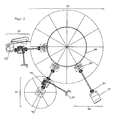
- FIG. 1 shows a device of a press-blowing machine 103, to which also a so-called takeout device belongs (taker) and which was marked with numeral 101.
- the press blow molding machine is driven by a main drive 100.
- the main drive acts on a pinion 105, which is in communication with a gear of the so-called carousel of the press blow molding machine.
- the pinion 105 drives a takeout 101 via a drive shaft.
- a transfer case 110 and a differential gear 108 are seated on the drive shaft.
- the transfer case 110 drives the drive of a drop feed device 102.
- the differential gear 108 is adjustable via a manual adjustment 107.
- the drop feeder 102 requires an adjustment, another differential gear and a drive of the drop feeder 102 by means of cam 109.
- coupling 104 is arranged in the interposed between the main drive and the pinion drive shaft coupling 104 is arranged.
- This structure reveals a complex arrangement of rankings of the respective drives or follower drives, all of which require a highly complicated specification and synchronization, so that the glass drop can be transferred accurately into the respective preform and further processing modules.
- the multiplicity of hierarchies and gear pairings additionally cause a game which is detrimental to the production process of the hollow bodies and which counteracts the highly complicated synchronization. Due to the high speeds of rotation and the above-mentioned games, the different, the main drive downstream gearbox to a permanent adjustment needs during operation, resulting not only in highly complex workflows, but also to a risk potential for the entrusted with these assets in the company employees of the company concerned leads.
- FIG. 2 There is another related art of such a press blow molding machine 103. This differs from the press blow molding machine 103 of FIG. 1 essentially in that the main drive 100 and the drive of the takeout 112 are separated from each other. The same applies in comparison to the drive 109 of the drop supply device 102.
- the drive motor 111 of the drive 100 stands with a drive shaft with the pinion gear 105 acting on the main gear 106 in conjunction.
- the main gear 106 drives the takeout 101 and the drop feed 102 via one drive shaft each.
- differential gear 108 are interposed, which are adjustable via a respective manual adjustment 107.
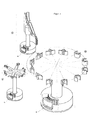
- FIG. 3 shows a rotary transformer 122, which in known devices for the production of hollow bodies, the media required for the production of the hollow body such as water 119, compressed air 118; 120 and blower air 113 provides.
- the media Perpendicular to a base plate 117 of the carousel, the media are supplied from one foot of the rotary transformer 122 to manifolds 121 which supply the media to consumers within the apparatus.
- electric slip ring transformer 114 are shown in the area of a control cabinet 115 electric slip ring transformer 114 are shown.
- the slip ring transmitters 114 are required for the supply of electrical energy and to ensure safety-relevant control voltage.
- the rotary transmitters 122 are arranged in the prior art in the center of the device for producing hollow bodies.
- the liquid lines are guided vertically below power-conducting components 114.
- the electric slip ring transmitters 114 and other pantographs must be replaced at regular intervals. For this purpose, a complete disassembly of affected components is required.
- the control cabinet 115, the controls 116 and the media distribution pipes 121st are affected.
- the invention is therefore based on the object to provide a device for producing hollow bodies, in which the aforementioned disadvantages are largely eliminated.
- the goal is to increase energy efficiency and to improve the continuous production run times of the machines.
- the invention has the object to improve a press-blow molding machine on the effectiveness of the production ratio and to increase the reproducible quality of the hollow body to be produced.
- the invention is based on an apparatus for producing hollow bodies from a molten glass, which has at least one carousel, which is preferably equipped with one or more preferably a plurality of segments.
- At least one glass gob is melted from a glass melt via at least one feed device, preferably fed via at least one feed channel, at least one preform.
- the device further comprises at least one of the molding of the hollow body serving means.
- servo drive means in particular any drive with electronic position, speed or torque control or a combination thereof.
- the servo drive and its various embodiments are known per se. Particularly preferred are at least for the ride on the carousel servo drives so-called decentralized servo drives (also called: Feldbusservorantriebe).
- decentralized servo drives also called: Feldbusservorantriebe.
- both the at least one feed device and the at least one takeout device each have at least one servo drive.
- This device preferably consists of at least one pressing device and / or at least one blowing device or a combination of both.
- the newly formed hollow body can be fed to at least one takeout device.
- a plurality of additional units may be arranged between the successive machining operations, which serve to implement the shape and the reaction of the hollow bodies produced.
- the device according to the invention typically has a carousel.
- This carousel typically has a base plate for receiving the working elements, in particular at least one preform, at least one pressing device, at least one blowing device, at least one ground station, at least one finished mold.
- the carousel also has energy and data transmitters, as well as the main drive.
- the patented device for producing hollow bodies from a molten glass also has at least one feeding device.
- a glass drop emerging from the molten glass is fed to the preform.
- the supply device may comprise various configurations, for example, be a cylindrical tube or be designed as a feed channel. Furthermore, it comprises an independent drive, in particular in the configuration of a servo drive.
- the device according to the invention has at least one takeout device, which is also referred to as a taker.
- This takeout device takes over the molded hollow body from the carousel. It is arranged adjacent to the carousel. Both sets of machines interlock.
- the carousel has a servo drive, preferably via a direct drive. Furthermore, the at least one feed device and the at least one takeout device each have at least one servo drive. These servo drives are preferably direct drives.
- such a direct drive consists of at least one active stator segment and at least one passive rotor element.
- a servo drive according to the invention in which the power transmission is effected by electromagnetic traction, eliminates any play and any wear between coupling members known from the prior art, which connect a main drive of the device with a drive of the drop feeder and the takeout.
- Another advantage is that the number of mechanical components and thus components to be maintained can be significantly reduced, which can also reduce the manufacturing costs. As a result, maintenance work can be largely avoided or maintenance intervals can be increased.
- the direct drive is relatively inexpensive to manufacture. As far as a direct drive is used in the feeding device, this is relatively easy to retrofit.
- servo drives also allows for predictive maintenance.
- the current operating states, limit values, contouring errors and / or current consumption can be stored for each production setting. Reference data is compared with data of the current operating state. In this way, messages and warnings can be generated before an incident occurs. Inspections or maintenance of the system are initiated before the incident, which makes revisions predictable and minimizes production and repair costs.
- the at least one carousel preferably has a plurality of sections and a section base.
- segment is also used for the term of the segment.
- the at least one section preferably includes all the facilities required to form hollow bodies from drops of molten glass.
- the sections are arranged on the at least one carousel of the device.
- the section base is an interface between the segment and the carousel.
- a section has at least one preform, at least one device serving to shape the hollow body, preferably a pressing device, at least one neck ring and at least one blowing device and optionally a ground station. Furthermore, the section may have a combined press-blower.
- Part of the pressing device is preferably a plunger and a neck ring.
- Part of the blower is u.a. the finished form, but which is not the subject of the present invention.
- the molding of a hollow body in a press-blow process is carried out in such a way that first the Kölbel is produced. This is typically done by pressing the glass drop with the aid of the at least one pressing device with the cooperation of preform, neck ring and plunger to the flask. In a subsequent process part cycle of the Kölbel is formed by means of the blowing device under their interaction with neck ring, finished mold and bottom to the hollow body. Pressing device and blowing device can be arranged combined in a machine component.
- the plunger is a component with which the glass gob is reshaped in the cavity between preform and neck ring to the Kölbel.
- the neck ring is arranged between plunger and preform; Its function is to receive and transport the preform or the Kölbel for the period from the preforming to the removal of the hollow body by the takeout.
- the at least one servo drive of the at least one carousel is the reference variable for all other drives, preferably all coupled auxiliary drives. Furthermore, it may be preferred that the at least one servo drive of either the at least one takeout device or the at least one feed device is the reference variable for all other drives.
- the movement speed corresponds to a predetermined period of the rotational speed of the carousel.
- the advantage of the invention is the bilateral velocity of the drop as the drop emerges from the feeder and enters its preform conforms to the rotational speed of the carousel.
- the timing at which the feeder and the center of the carousel preform overlap is the time at which the drop from the feeder passes into the preform.
- the peripheral speed of the carousel may be 1200 mm / s. This achieves a lateral movement of 12 mm per 1 / 100th of a second. From this it can be seen what great influence results from a fluctuation of the drop transfer time to the centric position of the drop in the preform.
- the invention avoids the error of conventionally driven feeders in transferring the drop to the preform.
- a supply device is to be understood as a supply channel.
- the at least one takeout device has at least one robot.
- the advantage is that the robot is electronically adaptable to the pressing device and blowing device or the combined press-blowing device.
- the robot is also easy to switch or change the sequence of movements, whereby a rapid adaptation to different shapes and characteristics of the hollow body to be produced is possible.
- a further preferred embodiment of the invention provides that the at least one carousel and / or the segment of the at least one carousel has at least one robot and / or that at least one of the two embodiments is a robot.
- the preform can be positioned in a defined waiting position on the segment of the pressing device or the blowing device.
- the robot picks up the preform, in particular grasps it and moves it into the drop feed position.
- the robot can move the preform counter to the peripheral speed of the carousel, whereby a significant reduction in the absolute speed of the preform is achieved. Due to this reduced speed, the quality of the drop feed is greatly improved.
- the robot preferably moves the preform with the droplets toward the pressing device.
- the preform is fixed by a device on the molding device of the hollow body serving pressing device and / or blowing device and / or combined press-blower.
- the device can realize the fixation pneumatically, magnetically, mechanically or hydraulically or from combinations thereof.
- the fixation can be solvable. This is followed by the formation of the Kölbels by the pressing device or a combined press-blower.
- the robot grips the preform in the pressing device and / or in the combined press-blowing device and returns the preform to the waiting position.
- the robot preferably grips the ground from a defined waiting position on the segment of the press-blow molding machine and moves the floor by a predefined movement sequence under the Kölbel. Due to the vertical movement of the soil under the Kölbel becamelend by gravity, the formation of the Kölbels can be positively controlled. This is followed by the final shaping of the hollow body by the blowing device or the combined press-blowing device. Subsequently, the robot resets the floor to the defined waiting position.
- the robot the finished molded hollow body with its gripper from the blowing device or the combined press-blower removes and feeds another unspecified transport device.
- the prearranged gripping movements in the sense of the present invention are also equated with such movements that are accomplished by other recording means.
- other recording means e.g. Suckers, magnets in consideration.
- the receiving means, in particular the grippers can be made according to the objects to be handled, e.g. Preform, bottom or hollow body, changed, adapted and adjusted.
- the robots are electronically coupled to the main drive of the machine. Another advantage is the simple switching or change of movement and a quick adaptation to different items and forms.
- the at least one robot can be arranged stationarily outside the carousel. Furthermore, the at least one robot be arranged stationarily outside the takeout device or the segment of the carousel. In this embodiment, during the operation of the device, the robot can specifically intervene in the carousel, in the takeout device or in a desired segment of the carousel from the outside. In this case, the robot foot does not track the continuous orbital movements of the carousel or takeout device.
- the stationary arrangement of the at least one robot outside of the aforementioned machine assemblies fulfills the same advantages as in the case of its running with the carousel arrangement;
- the decentralized and mechanically decoupled design ensures easy replacement of the robot or easy maintenance without time-consuming disassembly on the carousel.
- An embodiment of the invention provides that at least one servo drive is provided for moving the at least one preform from the drop supply positions to the at least one pressing device.
- This servo drive can be a linear motor.
- a torque motor when the drive kinematics requires the drive energy in rotational form, a torque motor.
- These drives may further preferably have toggle mechanism.
- These drives may further preferably have threaded spindle / threaded nut combinations.
- These drives can be further preferably designed as a cam gear.
- These drives may more preferably comprise chain and toothed belts.
- These drives can further preferably have crank drives.
- a further embodiment of the invention provides that the sequence of movements takes place mirror-inverted from the device serving for the movement of the molding of the hollow body to the at least one preform.
- the use of at least one servo drive is provided.
- This at least one servo drive can be a linear motor.
- a torque motor when the drive kinematics requires the drive energy in rotational form, a torque motor.
- These drives can further preferably toggle mechanism exhibit.
- These drives may further preferably have threaded spindle / threaded nut combinations.
- These drives can be further preferably designed as a cam gear.
- These drives may more preferably comprise chain and toothed belts.
- These drives can further preferably have crank drives.
- a further embodiment of the invention provides that at least one servo drive is provided for moving the at least one plunger relative to the at least one preform and / or to the at least one finished mold.
- This at least one servo drive can be a linear motor.
- a torque motor when the drive kinematics requires the drive energy in rotational form, a torque motor.
- These drives may further preferably have toggle mechanism.
- These drives may further preferably have threaded spindle / threaded nut combinations.
- These drives can be further preferably designed as a cam gear.
- These drives may more preferably comprise chain and toothed belts.
- These drives can further preferably have crank drives.
- the electrical energy transmission has at least one preferably stationary feed and at least one taker rotating with the carousel. It is also advantageous if the transmission of electrical energy takes place via a first primary part to a secondary part rotating with the carousel. By this embodiment, this energy transfer is contactless and thus inferior to wear in comparison to the embodiments of the prior art. The susceptibility to failure and the repair costs are thereby reduced.
- the energy transfer between the at least one feed and the at least one pickup, and thus between the primary and the secondary part can be made inductively.
- Induction windings transfer the statically supplied primary energy to a quiescent primary iron core.
- the primary energy passes from a primary iron core via an air gap to a secondary iron core and a secondary induction coil about, which rotates with the carousel of the apparatus for producing hollow bodies.
- the data transmission to the device takes place without contact.
- the increasing degree of automation and a steadily increasing share of intelligent actuators are leading to a constantly growing data volume.
- the invention proves to be advantageous because it ensures the speed and quality required for the transmission of the bus protocols in the data transmission.
- the performance of conventional rotary carriers is far exceeded.
- high-performance transmission protocols such as, for example, Profi-Bus, Device-Net or Profi-Net are used.
- the signals of each data channel have a light signal transmission.
- At least one pump is integrated into the device, which provides the water, vacuum, cooling air, compressed air or lubricating oil required for the production of the hollow body or the function of the device.
- a further embodiment of the invention provides that the pump is electrically operated and connected to a stationary annular channel for conveying water.
- the at least one pump is supplied via a contactless, energy transfer electrical current. All pumps for fuel supply can be exchanged in a very short time using simple connection points for maintenance purposes.
- At least one compressor is integrated in the device, which provides the compressed air required for processing the hollow body.
- the power supply of the compressor is contactless.
- the compressors have simple connection points and can be replaced at short notice for maintenance purposes.
- the use of compressors for the provision of compressed air proves to be advantageous because of an arrangement of a tube Management system can be dispensed with. The amount of investment and ongoing maintenance can be significantly reduced. In addition, there is a risk that the pipe system over the life of the device leaks, which must be repaired costly.
- the invention proves to be advantageous because the susceptibility of the device for the production of hollow bodies decreases and costly repairs are avoided. In addition, an increase in energy efficiency is achievable and an extension of the effective production time is possible. Likewise, the device according to the invention leads to a considerable improvement in the effectiveness of the production process and the quality of the hollow body to be produced.
- Fig. 4 shows in each case the servo drives 10; 11; 12 of the drop feed device 5, the takeout device 8 and the press-blower 16.
- the respective arrangement of the servo drives 10; 11; 12 at the feeder 5, the takeout device 8 and the press blower 16 in Fig. 4 is meant only as an example.
- the respective servo drives 10; 11; 12 also at other locations of the respective facilities 5; 8 and 16 may be arranged.
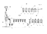
- Fig. 5 shows a molten glass 23, a drop-feeding device 5, and a pressing device 7 and a blowing device 25 of the device according to the invention for the production of hollow bodies 1.
- a drop 6 of a glass melt is shown, after passing through a feed device 5 in one, in a Drip feed positions 40 located preform 4 is fed.
- the feed device 5 has a servo drive designated by 10 (cf. Fig. 4 ) on.
- the droplet 6 is in the pressing position 39.
- a plunger 26 moves into the preform 4.
- a neck ring 30 is arranged.
- the glass melt is pressed in the pressing position 39 in the preform 4 between the outer wall of the plunger 13 and the inner wall 47 of the preform 4 in the direction of the neck ring 30.
- a preform (Kölbel 42) is formed inside the preform 4.
- the Kölbel 42 is held by the neck ring 30 and the preform 4 detached from Kölbel 42.
- the finished mold 24 surrounds the Kölbel 42.
- a bottom 31 is shown, which limits the, due to gravity and the supply of compressed air longitudinal expansion of the Kölbels 42.
- a gripper pliers designated 49 takes over the Kölbel from its holder in the neck ring and leads him to further processing.
- FIG. 6 shows the carousel 2 with the, the preform 4-bearing preform carrier 15.
- a shaping device is shown.
- the servo drive 12 of the carousel 2 is arranged in the center of the carousel 2. Radially outside the servo drive 12, the data channels designated 36 are recognizable.
- the drop feed position 40 a drop 6 is fed to the preform 4.
- a takeout device 8 comprises gripper tongs 49; 50 (in the open or closed state) and a servo drive 11. Radially outside the takeout device 8, a robot 14 is shown.
- FIG. 7 a robot 14 is shown, whose arms have an axis of rotation 48 about which the gripper tongs 49; 50 are rotatably arranged.
- the robot removes the hollow body 1 after completion of finished molding from the apparatus for producing hollow bodies and leads them to a further transport or processing device, not shown. This detection by the robot takes place in particular in the pressing device 7, in the blowing device 25 or in the combined press-blowing device.
Landscapes
- Engineering & Computer Science (AREA)
- Chemical & Material Sciences (AREA)
- Materials Engineering (AREA)
- Organic Chemistry (AREA)
- Manufacturing & Machinery (AREA)
- Mechanical Engineering (AREA)
- Blow-Moulding Or Thermoforming Of Plastics Or The Like (AREA)
- Glass Compositions (AREA)
Priority Applications (1)
| Application Number | Priority Date | Filing Date | Title |
|---|---|---|---|
| PL13160570T PL2647603T3 (pl) | 2012-04-03 | 2013-03-22 | Urządzenie do wytwarzania kształtek pustych w środku z masy szklanej |
Applications Claiming Priority (1)
| Application Number | Priority Date | Filing Date | Title |
|---|---|---|---|
| DE102012006659.7A DE102012006659B4 (de) | 2012-04-03 | 2012-04-03 | Vorrichtung zur Herstellung von Hohlkörpern aus einer Glasschmelze |
Publications (3)
| Publication Number | Publication Date |
|---|---|
| EP2647603A2 true EP2647603A2 (fr) | 2013-10-09 |
| EP2647603A3 EP2647603A3 (fr) | 2014-12-03 |
| EP2647603B1 EP2647603B1 (fr) | 2017-08-02 |
Family
ID=47915540
Family Applications (1)
| Application Number | Title | Priority Date | Filing Date |
|---|---|---|---|
| EP13160570.1A Not-in-force EP2647603B1 (fr) | 2012-04-03 | 2013-03-22 | Dispositif destiné à la fabrication de corps creux à partir d'un bain de verre |
Country Status (3)
| Country | Link |
|---|---|
| EP (1) | EP2647603B1 (fr) |
| DE (1) | DE102012006659B4 (fr) |
| PL (1) | PL2647603T3 (fr) |
Cited By (7)
| Publication number | Priority date | Publication date | Assignee | Title |
|---|---|---|---|---|
| WO2015095055A3 (fr) * | 2013-12-19 | 2015-10-08 | Owens-Brockway Glass Container Inc. | Système de bague de goulot et procédé de façonnage d'articles en verre |
| EP2960215A1 (fr) * | 2012-04-27 | 2015-12-30 | Waltec Maschinen GmbH | Dispositif destine a la fabrication de corps creux a partir d'un bain de verre |
| CN107200463A (zh) * | 2017-07-21 | 2017-09-26 | 唐洲 | 先闷后冲成型小腰玻璃器皿的玻璃压机 |
| CN110342787A (zh) * | 2019-07-22 | 2019-10-18 | 河北明尚德玻璃科技股份有限公司 | 一种不受玻璃器皿高度及造型限制的爆口设备 |
| CN110615604A (zh) * | 2018-06-19 | 2019-12-27 | 肖特瑞士股份公司 | 用于控制热成型机的旋转驱动的方法 |
| CN112830663A (zh) * | 2021-03-02 | 2021-05-25 | 南通威明精工机械有限公司 | 一种压饼式吹泡机上料结构 |
| CN114560620A (zh) * | 2022-02-23 | 2022-05-31 | 重庆星源玻璃器皿有限责任公司 | 一种玻璃容器生产系统 |
Citations (2)
| Publication number | Priority date | Publication date | Assignee | Title |
|---|---|---|---|---|
| US4052187A (en) | 1974-12-09 | 1977-10-04 | Villeroy & Boch Keramische Werke Kg | Apparatus for producing glass parison by the press-and-blow process |
| DE602004008092T2 (de) | 2003-10-03 | 2008-04-24 | Olivotto Glass Technologies S.P.A. | Pressblasmaschine für die herstellung von hohlen glaswaren |
Family Cites Families (14)
| Publication number | Priority date | Publication date | Assignee | Title |
|---|---|---|---|---|
| US3803877A (en) * | 1968-03-26 | 1974-04-16 | Heye H | Press and blow machine for the production of containers |
| JPS6013982B2 (ja) * | 1981-08-03 | 1985-04-10 | 扶桑精工株式会社 | 溶融ガラス分配装置 |
| GB2162484A (en) * | 1984-08-03 | 1986-02-05 | Emhart Ind | Transferring articles of glassware from a blow station to conveyor means |
| US4599101A (en) * | 1985-05-15 | 1986-07-08 | Emhart Industries, Inc. | Universal servo-driven gob distributor |
| US4723977A (en) * | 1986-11-19 | 1988-02-09 | Emhart Industries, Inc. | Electronic servo control of glass gob distribution |
| JP2549972B2 (ja) * | 1992-10-06 | 1996-10-30 | 東洋ガラス株式会社 | 製びん機のゴブ分配装置 |
| DE29810353U1 (de) * | 1998-06-12 | 1999-07-15 | Fa. Hermann Heye, 31683 Obernkirchen | Ausnehmer-Mechanismus für eine Glasformmaschine |
| JP3140434B2 (ja) * | 1999-05-14 | 2001-03-05 | 東洋ガラス株式会社 | 製びん機のテークアウトメカニズム |
| DE10106059A1 (de) * | 2001-02-09 | 2002-09-05 | Schott Glas | Elektrisch gesteuerte Blasstation |
| US6604384B2 (en) * | 2001-04-10 | 2003-08-12 | Emhart Glass, S.A. | Control for an I.S. machine |
| JP4181394B2 (ja) * | 2002-12-05 | 2008-11-12 | 東芝機械株式会社 | ガラス成形システム |
| JP4301818B2 (ja) * | 2003-01-10 | 2009-07-22 | 東芝機械株式会社 | ガラス成形システム |
| DE20303444U1 (de) * | 2003-03-04 | 2004-04-08 | Heye International Gmbh | Tropfenverteiler für eine Glasformmaschine |
| FR2938254B1 (fr) * | 2008-11-12 | 2011-08-19 | Saint Gobain Emballage | Substitution automatique de moules ebaucheurs dans la fabrication de produits en verre creux |
-
2012
- 2012-04-03 DE DE102012006659.7A patent/DE102012006659B4/de not_active Expired - Fee Related
-
2013
- 2013-03-22 EP EP13160570.1A patent/EP2647603B1/fr not_active Not-in-force
- 2013-03-22 PL PL13160570T patent/PL2647603T3/pl unknown
Patent Citations (2)
| Publication number | Priority date | Publication date | Assignee | Title |
|---|---|---|---|---|
| US4052187A (en) | 1974-12-09 | 1977-10-04 | Villeroy & Boch Keramische Werke Kg | Apparatus for producing glass parison by the press-and-blow process |
| DE602004008092T2 (de) | 2003-10-03 | 2008-04-24 | Olivotto Glass Technologies S.P.A. | Pressblasmaschine für die herstellung von hohlen glaswaren |
Cited By (13)
| Publication number | Priority date | Publication date | Assignee | Title |
|---|---|---|---|---|
| EP2960215A1 (fr) * | 2012-04-27 | 2015-12-30 | Waltec Maschinen GmbH | Dispositif destine a la fabrication de corps creux a partir d'un bain de verre |
| US9676647B2 (en) | 2013-12-19 | 2017-06-13 | Owens-Brockway Glass Container Inc. | Neck ring system and glassware forming process |
| US9950943B2 (en) | 2013-12-19 | 2018-04-24 | Owens-Brockway Glass Container Inc. | Neck ring system and glassware forming process |
| EP3333132A3 (fr) * | 2013-12-19 | 2018-09-26 | Owens-Brockway Glass Container Inc. | Procédé de faconnage d'articles en verre |
| WO2015095055A3 (fr) * | 2013-12-19 | 2015-10-08 | Owens-Brockway Glass Container Inc. | Système de bague de goulot et procédé de façonnage d'articles en verre |
| EP3805166A1 (fr) | 2013-12-19 | 2021-04-14 | Owens-Brockway Glass Container Inc. | Système de bague de goulot et procédé de façonnage d'articles en verre |
| CN107200463A (zh) * | 2017-07-21 | 2017-09-26 | 唐洲 | 先闷后冲成型小腰玻璃器皿的玻璃压机 |
| CN110615604B (zh) * | 2018-06-19 | 2022-11-11 | 肖特瑞士股份公司 | 用于控制热成型机的旋转驱动的方法 |
| CN110615604A (zh) * | 2018-06-19 | 2019-12-27 | 肖特瑞士股份公司 | 用于控制热成型机的旋转驱动的方法 |
| CN110342787A (zh) * | 2019-07-22 | 2019-10-18 | 河北明尚德玻璃科技股份有限公司 | 一种不受玻璃器皿高度及造型限制的爆口设备 |
| CN112830663A (zh) * | 2021-03-02 | 2021-05-25 | 南通威明精工机械有限公司 | 一种压饼式吹泡机上料结构 |
| CN114560620A (zh) * | 2022-02-23 | 2022-05-31 | 重庆星源玻璃器皿有限责任公司 | 一种玻璃容器生产系统 |
| CN114560620B (zh) * | 2022-02-23 | 2024-04-23 | 重庆星源玻璃器皿有限责任公司 | 一种玻璃容器生产系统 |
Also Published As
| Publication number | Publication date |
|---|---|
| DE102012006659B4 (de) | 2017-01-12 |
| EP2647603B1 (fr) | 2017-08-02 |
| DE102012006659A1 (de) | 2013-10-10 |
| PL2647603T3 (pl) | 2017-11-30 |
| EP2647603A3 (fr) | 2014-12-03 |
Similar Documents
| Publication | Publication Date | Title |
|---|---|---|
| EP2647603B1 (fr) | Dispositif destiné à la fabrication de corps creux à partir d'un bain de verre | |
| CN204953732U (zh) | 集成一体式全自动制罐机 | |
| EP2266773A2 (fr) | Procédé et dispositif pour mouler par injection et assembler des pieces en plastique | |
| EP2731779B1 (fr) | Machine de moulage par soufflage pour récipients en plastique | |
| DE3717799C2 (de) | Einrichtung zum Pressen von Frontplatten von Kathodenstrahlröhren | |
| EP2960215B1 (fr) | Dispositif destine a la fabrication de corps creux a partir d'un bain de verre | |
| WO2019145449A1 (fr) | Dispositif de façonnage à chaud pour la fabrication de récipients en verre à partir d'un tube de verre | |
| DE102015121884B4 (de) | Umform- und/oder Transferpresse mit zwei Stationsreihen und mit einer Transportvorrichtung zum Transport von Werkstücken entlang der aufeinanderfolgenden Bearbeitungstationen sowie Verfahren zum Fertigen von Produkten aus Werkstücken | |
| DE102012103957B4 (de) | Vorrichtung zur Herstellung von Hohlkörpern aus einer Glasschmelze | |
| EP3743389B1 (fr) | Dispositif de mise en forme à chaud pour la fabrication de contenants en verre à partir d'un tube en verre | |
| EP0427215B1 (fr) | Machine à poinçonner des rainures | |
| DE102006034878B3 (de) | Anordnung zum Herstellen von Glaskörpern | |
| CN205085605U (zh) | 一种自动化蜗杆轴滚压设备 | |
| EP2669258B1 (fr) | Apprareil pour produire des articles de verre creux à partir d'un verre fondu | |
| DE102012107385B4 (de) | Vorrichtung zur Herstellung und Weiterbearbeitung eines Glaskörpers mit wenigstens einem Glaskörper | |
| US3951636A (en) | Molding apparatus | |
| DE202012101935U1 (de) | Vorrichtung zur Herstellung von Hohlkörpern aus einer Glasschmelze | |
| EP2985130B2 (fr) | Dispositif de transformation d'ebauches en matiere plastique en recipients en matiere plastique | |
| CN206913179U (zh) | 压力机用单臂机械手 | |
| EP1908734A1 (fr) | Procédé et dispositif destinés à la fabrication de pots en verre | |
| CN121374163A (zh) | 一种花兰体的加工装置及其加工方法 | |
| DE202006011569U1 (de) | Anordnung zum Herstellen von Glaskörpern | |
| DD246456A3 (de) | Maschinensystem zum Nachformen von Glasrohren |
Legal Events
| Date | Code | Title | Description |
|---|---|---|---|
| PUAI | Public reference made under article 153(3) epc to a published international application that has entered the european phase |
Free format text: ORIGINAL CODE: 0009012 |
|
| AK | Designated contracting states |
Kind code of ref document: A2 Designated state(s): AL AT BE BG CH CY CZ DE DK EE ES FI FR GB GR HR HU IE IS IT LI LT LU LV MC MK MT NL NO PL PT RO RS SE SI SK SM TR |
|
| AX | Request for extension of the european patent |
Extension state: BA ME |
|
| PUAL | Search report despatched |
Free format text: ORIGINAL CODE: 0009013 |
|
| AK | Designated contracting states |
Kind code of ref document: A3 Designated state(s): AL AT BE BG CH CY CZ DE DK EE ES FI FR GB GR HR HU IE IS IT LI LT LU LV MC MK MT NL NO PL PT RO RS SE SI SK SM TR |
|
| AX | Request for extension of the european patent |
Extension state: BA ME |
|
| RIC1 | Information provided on ipc code assigned before grant |
Ipc: C03B 7/16 20060101AFI20141028BHEP Ipc: C03B 9/41 20060101ALI20141028BHEP Ipc: C03B 9/447 20060101ALI20141028BHEP Ipc: C03B 9/195 20060101ALI20141028BHEP |
|
| 17P | Request for examination filed |
Effective date: 20150603 |
|
| RBV | Designated contracting states (corrected) |
Designated state(s): AL AT BE BG CH CY CZ DE DK EE ES FI FR GB GR HR HU IE IS IT LI LT LU LV MC MK MT NL NO PL PT RO RS SE SI SK SM TR |
|
| 17Q | First examination report despatched |
Effective date: 20160530 |
|
| GRAP | Despatch of communication of intention to grant a patent |
Free format text: ORIGINAL CODE: EPIDOSNIGR1 |
|
| INTG | Intention to grant announced |
Effective date: 20170224 |
|
| GRAS | Grant fee paid |
Free format text: ORIGINAL CODE: EPIDOSNIGR3 |
|
| GRAA | (expected) grant |
Free format text: ORIGINAL CODE: 0009210 |
|
| AK | Designated contracting states |
Kind code of ref document: B1 Designated state(s): AL AT BE BG CH CY CZ DE DK EE ES FI FR GB GR HR HU IE IS IT LI LT LU LV MC MK MT NL NO PL PT RO RS SE SI SK SM TR |
|
| REG | Reference to a national code |
Ref country code: CH Ref legal event code: EP Ref country code: AT Ref legal event code: REF Ref document number: 914251 Country of ref document: AT Kind code of ref document: T Effective date: 20170815 |
|
| REG | Reference to a national code |
Ref country code: IE Ref legal event code: FG4D Free format text: LANGUAGE OF EP DOCUMENT: GERMAN |
|
| REG | Reference to a national code |
Ref country code: DE Ref legal event code: R096 Ref document number: 502013007896 Country of ref document: DE |
|
| REG | Reference to a national code |
Ref country code: CH Ref legal event code: NV Representative=s name: RA THOMAS KOHLI C/O KLOTER AND KOHLI RECHTSANW, CH |
|
| REG | Reference to a national code |
Ref country code: CH Ref legal event code: PFA Owner name: WALTEC MASCHINEN GMBH, DE Free format text: FORMER OWNER: WALTEC MASCHINEN GMBH, DE |
|
| REG | Reference to a national code |
Ref country code: NL Ref legal event code: MP Effective date: 20170802 |
|
| REG | Reference to a national code |
Ref country code: LT Ref legal event code: MG4D |
|
| PG25 | Lapsed in a contracting state [announced via postgrant information from national office to epo] |
Ref country code: HR Free format text: LAPSE BECAUSE OF FAILURE TO SUBMIT A TRANSLATION OF THE DESCRIPTION OR TO PAY THE FEE WITHIN THE PRESCRIBED TIME-LIMIT Effective date: 20170802 Ref country code: NL Free format text: LAPSE BECAUSE OF FAILURE TO SUBMIT A TRANSLATION OF THE DESCRIPTION OR TO PAY THE FEE WITHIN THE PRESCRIBED TIME-LIMIT Effective date: 20170802 Ref country code: FI Free format text: LAPSE BECAUSE OF FAILURE TO SUBMIT A TRANSLATION OF THE DESCRIPTION OR TO PAY THE FEE WITHIN THE PRESCRIBED TIME-LIMIT Effective date: 20170802 Ref country code: SE Free format text: LAPSE BECAUSE OF FAILURE TO SUBMIT A TRANSLATION OF THE DESCRIPTION OR TO PAY THE FEE WITHIN THE PRESCRIBED TIME-LIMIT Effective date: 20170802 Ref country code: LT Free format text: LAPSE BECAUSE OF FAILURE TO SUBMIT A TRANSLATION OF THE DESCRIPTION OR TO PAY THE FEE WITHIN THE PRESCRIBED TIME-LIMIT Effective date: 20170802 Ref country code: NO Free format text: LAPSE BECAUSE OF FAILURE TO SUBMIT A TRANSLATION OF THE DESCRIPTION OR TO PAY THE FEE WITHIN THE PRESCRIBED TIME-LIMIT Effective date: 20171102 |
|
| REG | Reference to a national code |
Ref country code: DE Ref legal event code: R082 Ref document number: 502013007896 Country of ref document: DE Representative=s name: LS-MP VON PUTTKAMER BERNGRUBER LOTH SPUHLER PA, DE |
|
| PG25 | Lapsed in a contracting state [announced via postgrant information from national office to epo] |
Ref country code: LV Free format text: LAPSE BECAUSE OF FAILURE TO SUBMIT A TRANSLATION OF THE DESCRIPTION OR TO PAY THE FEE WITHIN THE PRESCRIBED TIME-LIMIT Effective date: 20170802 Ref country code: RS Free format text: LAPSE BECAUSE OF FAILURE TO SUBMIT A TRANSLATION OF THE DESCRIPTION OR TO PAY THE FEE WITHIN THE PRESCRIBED TIME-LIMIT Effective date: 20170802 Ref country code: IS Free format text: LAPSE BECAUSE OF FAILURE TO SUBMIT A TRANSLATION OF THE DESCRIPTION OR TO PAY THE FEE WITHIN THE PRESCRIBED TIME-LIMIT Effective date: 20171202 Ref country code: BG Free format text: LAPSE BECAUSE OF FAILURE TO SUBMIT A TRANSLATION OF THE DESCRIPTION OR TO PAY THE FEE WITHIN THE PRESCRIBED TIME-LIMIT Effective date: 20171102 Ref country code: GR Free format text: LAPSE BECAUSE OF FAILURE TO SUBMIT A TRANSLATION OF THE DESCRIPTION OR TO PAY THE FEE WITHIN THE PRESCRIBED TIME-LIMIT Effective date: 20171103 Ref country code: ES Free format text: LAPSE BECAUSE OF FAILURE TO SUBMIT A TRANSLATION OF THE DESCRIPTION OR TO PAY THE FEE WITHIN THE PRESCRIBED TIME-LIMIT Effective date: 20170802 |
|
| REG | Reference to a national code |
Ref country code: FR Ref legal event code: PLFP Year of fee payment: 6 |
|
| PG25 | Lapsed in a contracting state [announced via postgrant information from national office to epo] |
Ref country code: DK Free format text: LAPSE BECAUSE OF FAILURE TO SUBMIT A TRANSLATION OF THE DESCRIPTION OR TO PAY THE FEE WITHIN THE PRESCRIBED TIME-LIMIT Effective date: 20170802 Ref country code: RO Free format text: LAPSE BECAUSE OF FAILURE TO SUBMIT A TRANSLATION OF THE DESCRIPTION OR TO PAY THE FEE WITHIN THE PRESCRIBED TIME-LIMIT Effective date: 20170802 |
|
| REG | Reference to a national code |
Ref country code: DE Ref legal event code: R097 Ref document number: 502013007896 Country of ref document: DE |
|
| PG25 | Lapsed in a contracting state [announced via postgrant information from national office to epo] |
Ref country code: SK Free format text: LAPSE BECAUSE OF FAILURE TO SUBMIT A TRANSLATION OF THE DESCRIPTION OR TO PAY THE FEE WITHIN THE PRESCRIBED TIME-LIMIT Effective date: 20170802 Ref country code: EE Free format text: LAPSE BECAUSE OF FAILURE TO SUBMIT A TRANSLATION OF THE DESCRIPTION OR TO PAY THE FEE WITHIN THE PRESCRIBED TIME-LIMIT Effective date: 20170802 Ref country code: SM Free format text: LAPSE BECAUSE OF FAILURE TO SUBMIT A TRANSLATION OF THE DESCRIPTION OR TO PAY THE FEE WITHIN THE PRESCRIBED TIME-LIMIT Effective date: 20170802 |
|
| PLBE | No opposition filed within time limit |
Free format text: ORIGINAL CODE: 0009261 |
|
| STAA | Information on the status of an ep patent application or granted ep patent |
Free format text: STATUS: NO OPPOSITION FILED WITHIN TIME LIMIT |
|
| 26N | No opposition filed |
Effective date: 20180503 |
|
| PG25 | Lapsed in a contracting state [announced via postgrant information from national office to epo] |
Ref country code: SI Free format text: LAPSE BECAUSE OF FAILURE TO SUBMIT A TRANSLATION OF THE DESCRIPTION OR TO PAY THE FEE WITHIN THE PRESCRIBED TIME-LIMIT Effective date: 20170802 |
|
| PG25 | Lapsed in a contracting state [announced via postgrant information from national office to epo] |
Ref country code: MT Free format text: LAPSE BECAUSE OF FAILURE TO SUBMIT A TRANSLATION OF THE DESCRIPTION OR TO PAY THE FEE WITHIN THE PRESCRIBED TIME-LIMIT Effective date: 20170802 |
|
| GBPC | Gb: european patent ceased through non-payment of renewal fee |
Effective date: 20180322 |
|
| PG25 | Lapsed in a contracting state [announced via postgrant information from national office to epo] |
Ref country code: MC Free format text: LAPSE BECAUSE OF FAILURE TO SUBMIT A TRANSLATION OF THE DESCRIPTION OR TO PAY THE FEE WITHIN THE PRESCRIBED TIME-LIMIT Effective date: 20170802 |
|
| REG | Reference to a national code |
Ref country code: BE Ref legal event code: MM Effective date: 20180331 |
|
| REG | Reference to a national code |
Ref country code: IE Ref legal event code: MM4A |
|
| PG25 | Lapsed in a contracting state [announced via postgrant information from national office to epo] |
Ref country code: LU Free format text: LAPSE BECAUSE OF NON-PAYMENT OF DUE FEES Effective date: 20180322 |
|
| PG25 | Lapsed in a contracting state [announced via postgrant information from national office to epo] |
Ref country code: IE Free format text: LAPSE BECAUSE OF NON-PAYMENT OF DUE FEES Effective date: 20180322 |
|
| PG25 | Lapsed in a contracting state [announced via postgrant information from national office to epo] |
Ref country code: BE Free format text: LAPSE BECAUSE OF NON-PAYMENT OF DUE FEES Effective date: 20180331 Ref country code: GB Free format text: LAPSE BECAUSE OF NON-PAYMENT OF DUE FEES Effective date: 20180322 |
|
| PGFP | Annual fee paid to national office [announced via postgrant information from national office to epo] |
Ref country code: RO Payment date: 20180710 Year of fee payment: 8 Ref country code: FR Payment date: 20190315 Year of fee payment: 7 Ref country code: CH Payment date: 20190322 Year of fee payment: 7 Ref country code: CZ Payment date: 20190312 Year of fee payment: 7 |
|
| PGFP | Annual fee paid to national office [announced via postgrant information from national office to epo] |
Ref country code: AT Payment date: 20190318 Year of fee payment: 7 Ref country code: TR Payment date: 20190308 Year of fee payment: 7 |
|
| PGFP | Annual fee paid to national office [announced via postgrant information from national office to epo] |
Ref country code: DE Payment date: 20190517 Year of fee payment: 7 |
|
| PGFP | Annual fee paid to national office [announced via postgrant information from national office to epo] |
Ref country code: PL Payment date: 20200220 Year of fee payment: 8 |
|
| PG25 | Lapsed in a contracting state [announced via postgrant information from national office to epo] |
Ref country code: PT Free format text: LAPSE BECAUSE OF FAILURE TO SUBMIT A TRANSLATION OF THE DESCRIPTION OR TO PAY THE FEE WITHIN THE PRESCRIBED TIME-LIMIT Effective date: 20170802 Ref country code: HU Free format text: LAPSE BECAUSE OF FAILURE TO SUBMIT A TRANSLATION OF THE DESCRIPTION OR TO PAY THE FEE WITHIN THE PRESCRIBED TIME-LIMIT; INVALID AB INITIO Effective date: 20130322 |
|
| PG25 | Lapsed in a contracting state [announced via postgrant information from national office to epo] |
Ref country code: MK Free format text: LAPSE BECAUSE OF NON-PAYMENT OF DUE FEES Effective date: 20170802 Ref country code: CY Free format text: LAPSE BECAUSE OF FAILURE TO SUBMIT A TRANSLATION OF THE DESCRIPTION OR TO PAY THE FEE WITHIN THE PRESCRIBED TIME-LIMIT Effective date: 20170802 |
|
| PG25 | Lapsed in a contracting state [announced via postgrant information from national office to epo] |
Ref country code: AL Free format text: LAPSE BECAUSE OF FAILURE TO SUBMIT A TRANSLATION OF THE DESCRIPTION OR TO PAY THE FEE WITHIN THE PRESCRIBED TIME-LIMIT Effective date: 20170802 |
|
| REG | Reference to a national code |
Ref country code: DE Ref legal event code: R119 Ref document number: 502013007896 Country of ref document: DE |
|
| PG25 | Lapsed in a contracting state [announced via postgrant information from national office to epo] |
Ref country code: CZ Free format text: LAPSE BECAUSE OF NON-PAYMENT OF DUE FEES Effective date: 20200322 |
|
| REG | Reference to a national code |
Ref country code: CH Ref legal event code: PL |
|
| REG | Reference to a national code |
Ref country code: AT Ref legal event code: MM01 Ref document number: 914251 Country of ref document: AT Kind code of ref document: T Effective date: 20200322 |
|
| PG25 | Lapsed in a contracting state [announced via postgrant information from national office to epo] |
Ref country code: DE Free format text: LAPSE BECAUSE OF NON-PAYMENT OF DUE FEES Effective date: 20201001 Ref country code: AT Free format text: LAPSE BECAUSE OF NON-PAYMENT OF DUE FEES Effective date: 20200322 Ref country code: CH Free format text: LAPSE BECAUSE OF NON-PAYMENT OF DUE FEES Effective date: 20200331 Ref country code: LI Free format text: LAPSE BECAUSE OF NON-PAYMENT OF DUE FEES Effective date: 20200331 Ref country code: FR Free format text: LAPSE BECAUSE OF NON-PAYMENT OF DUE FEES Effective date: 20200331 |
|
| PG25 | Lapsed in a contracting state [announced via postgrant information from national office to epo] |
Ref country code: IT Free format text: LAPSE BECAUSE OF NON-PAYMENT OF DUE FEES Effective date: 20200322 |
|
| PG25 | Lapsed in a contracting state [announced via postgrant information from national office to epo] |
Ref country code: TR Free format text: LAPSE BECAUSE OF NON-PAYMENT OF DUE FEES Effective date: 20200322 |
|
| PG25 | Lapsed in a contracting state [announced via postgrant information from national office to epo] |
Ref country code: PL Free format text: LAPSE BECAUSE OF NON-PAYMENT OF DUE FEES Effective date: 20210322 |