EP2648103A2 - Procédé et dispositif d'intégration de systèmes techniques - Google Patents
Procédé et dispositif d'intégration de systèmes techniques Download PDFInfo
- Publication number
- EP2648103A2 EP2648103A2 EP13001509.2A EP13001509A EP2648103A2 EP 2648103 A2 EP2648103 A2 EP 2648103A2 EP 13001509 A EP13001509 A EP 13001509A EP 2648103 A2 EP2648103 A2 EP 2648103A2
- Authority
- EP
- European Patent Office
- Prior art keywords
- central computer
- component
- simulator
- integration
- components
- Prior art date
- Legal status (The legal status is an assumption and is not a legal conclusion. Google has not performed a legal analysis and makes no representation as to the accuracy of the status listed.)
- Ceased
Links
Images


Classifications
-
- G—PHYSICS
- G05—CONTROLLING; REGULATING
- G05B—CONTROL OR REGULATING SYSTEMS IN GENERAL; FUNCTIONAL ELEMENTS OF SUCH SYSTEMS; MONITORING OR TESTING ARRANGEMENTS FOR SUCH SYSTEMS OR ELEMENTS
- G05B17/00—Systems involving the use of models or simulators of said systems
- G05B17/02—Systems involving the use of models or simulators of said systems electric
-
- G—PHYSICS
- G06—COMPUTING OR CALCULATING; COUNTING
- G06F—ELECTRIC DIGITAL DATA PROCESSING
- G06F11/00—Error detection; Error correction; Monitoring
- G06F11/22—Detection or location of defective computer hardware by testing during standby operation or during idle time, e.g. start-up testing
- G06F11/26—Functional testing
- G06F11/261—Functional testing by simulating additional hardware, e.g. fault simulation
Definitions
- the present invention relates to a method for the integration of technical systems according to the preamble of patent claim 1. It further relates to a device for the integration of technical systems according to the preamble of patent claim 4.
- Complex technical systems such as motor vehicles, aircraft or even weapons systems consist of a variety of functional components, which are manufactured by different manufacturers as vendor parts and are assembled by a parent manufacturer (system integrator) to the functional whole.
- the components interact not only mechanically and electrically with each other, but there is a lively exchange of data between the individual components, more precisely between data processing equipment and sensors and actuators of the individual components, with corresponding elements of other components and / or a central Data processing device, the central computer, the technical system instead.
- This data communication between the individual components and the central computer takes place not only at the hardware level, but also at the software level. It must be ensured that these interactions work and do not lead to errors in the operation of the operating system of the entire technical system.
- Another object is to provide a device for the integration of technical systems, which enables the implementation of the method according to the invention.
- the central computer is first integrated with component simulators connected thereto and these Whole unit is tested and then successively replaced in each case a component simulator by a component and then carried out a further functional test of the entire unit until all components have been connected to the central computer to the entire system.
- This step-by-step procedure, each with a functional test after the installation of a new component means that any faults that still occur can be assigned directly to this component or to the interaction of this component with the central computer. This significantly simplifies troubleshooting the integration compared to troubleshooting, which is performed only after all components have been installed.
- the respective component simulators are tested against the at least one central computer simulator before the respective tests of the central computer and / or the components.
- These tests of the simulators against each other which virtually map the entire technical system or its functionality, ensure that the simulators operate error-free and thus serve as a reliable reference standard for the functionality of each of them simulated component. This rules out the possibility of producing errors in the implementation of the method according to the invention, the causes of which lie in the respective simulator.
- the directed to the device part of the object is achieved by the device with the features of claim 4.
- This device for the integration of technical systems consisting of a plurality of functional components which are designed for communication with a central computer of the technical system and connectable to the latter for data exchange with the formation of interfaces, is characterized in that at least one component simulator and at least one central computer simulator are provided.
- this device according to the invention which consists of a plurality of simulators, the individual components of the technical system can be tested in a particularly reliable manner when carrying out the method according to the invention.
- a simulator pair consisting of a component simulator and a component central computer simulator, which simulates the relevant functions of the central computer relative to this component, is provided for each component.
- the basic idea of the present invention is therefore to provide virtual mirror images of the functionality of the respective component of the technical system and the central computer of the technical system as corresponding simulators to the system integrator and then at an early stage, but at the latest during component production, the component against hers each associated central computer simulator or to test the central computer against the individual component simulators, so as to detect any errors at an early stage at the manufacturer of the respective component or the central computer and to avoid that such errors are recognized only in the course of integration with the system integrator.
- inventive method for the integration of technical systems and the associated device are shown below with reference to an example of military technology, wherein the technical system to be integrated is a weapon system 1, which has a weapon system 2 as subsystem, which also according to the inventive method for the integration of technical systems, ie here the subsystem weapon system, is integrated.
- a weapon system which has a weapon system 2 as subsystem
- the inventive method for the integration of technical systems ie here the subsystem weapon system
- the present invention will be shown and described below with reference to a weapon system, the invention is not limited to the military field, and in particular not to weapon systems, but is applicable to all technical systems with complex communication and interaction structure.
- Weapon system 1 illustrated as a system architecture diagram includes a weapon system center 10 and a plurality of weapon system subsystems 12, 14, 16 connected to the weapon system center 10 via data communication links. Furthermore, the weapon system 1, the subsystem weapons system 2, which is also connected to the Kumarsystemmin via a data transmission connection for data exchange.
- the weapon system 2 is mounted, for example, on a carrier vehicle 5.
- the weapon system center 10 of the weapon system 1 is connected via a further data transmission connection with a higher-level operation center 3 for data exchange.
- the said data transmission connections can be wired or wireless data transmission connections.
- the subsystem weapon system 2 has a central computer 20 with an operating unit 21, a communication system 22, an electrically or hydraulically operated antenna extension system 23 with a first antenna 23 'and a second antenna 23 ", an energy system 24, a missile erecting system 25 for at least one missile 4 and a navigation system 26. These individual systems are connected via corresponding data lines to the central computer 20 for data transmission.
- the first antenna 23 'of the antenna extension system 23 is provided for data communication with an already launched missile 4' and the second antenna 23 "of the antenna extension system is provided for data communication with the weapon system center 10.
- This representation of the weapon system 1 and the subsystem weapon system 2 shows the complexity of the respective systems with their individual components formed by the respective systems, which originate from different manufacturing plants and are to be integrated by a system integrator to the subsystem weapon system 2 or then to the entire weapon system 1.
- the system integrator only manufactures the wiring harness of the weapon system according to the specified signal specifications.
- the individual components of the weapon system are developed by different manufacturers according to the specified specification and tested and accepted at their own discretion. These individual components of the weapon system are supplied to the system integrator with more or less long delays; However, the system integrator has a fixed deadline for the delivery of the entire complex system, here the weapon system.
- a component simulator is provided for each of the components, that is to say for each of the systems, and furthermore a central computer simulator is provided.
- Fig. 2 shows a pairing of the central computer simulator (EA) 20 EA and a power plant simulator 24 S , which are connected to each other via a data connection (Ethernet line) for data exchange.
- the central computer simulator (EA) 20 EA simulates that part of the central computer 20 that is required for communication with the power plant 24.
- the energy system simulator 24 S simulates the behavior of the energy system at the interface to the central computer or to the data bus connected to the central computer. Leaving these two simulators 20 EA and 24 S , as in Fig. 2 is shown, communicating and interacting with each other, no errors should occur.
- each simulator is PC-based, that is implemented as software that is stored on a computer, such as a laptop executable.
- Each simulator implements the communication protocol defined for it according to the specification of the entire technical system.
- fault analysis tools are installed in the corresponding simulation software, which can output a corresponding error message (for example "unknown message ID", "incorrect message checksum” or "violations of handshake protocols") to an operator during errors occurring during a test .
- each simulator allows a manual mode in which a corresponding operator must trigger certain steps of the simulation process by hand or manually enter status messages.
- each simulator implements selectable automatisms (for example, a state machine).
- Each simulator has a message-oriented user interface with windows for displaying received messages as well as windows for setting transmission messages. The simulators are also designed to record the individual simulation steps, to log and replay them using a replay function.
- Fig. 3 shows how a central computer simulator (in the example shown, the central computer simulator (FA) of the missile erector) with a real Missile Erector 25 is connected via an Ethernet connection line for data exchange.
- 25 measuring devices 25 ' are connected to the real missile elevation system.
- This in Fig. 3 Test setup shows the final acceptance test to be carried out by the manufacturer of the missile erection system, after which the missile erecting system may first be delivered to the system integrator.
- the system integrator also uses a respective component-related central computer simulator in order to carry out an input analysis with the real components obtained from the respective manufacturer. This ensures that the system integrator uses only correctly functioning components when integrating the complete technical system.
- the test setup of the input detection corresponds to that in Fig. 3 shown test setup.
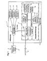
- Fig. 4 shows the starting point of an integration carried out according to the method of the invention.
- the central computer 20 with its operating unit 21 is connected via the corresponding lines of the wiring harness or data bus' 27.
- a communication system simulator 22 S Connected to this data bus 27 are a communication system simulator 22 S , an antenna deployment facility simulator 23 S , the power plant simulator 24 S , a missile erector facility simulator 25 S, and a navigation facility simulator 26 S.
- a missile simulator 4 S is connected to the data bus 27 and via this to the central computer 20.
- a weapon system central simulator 10 S is connected to the data bus 27 and connected to the central computer 20 via the latter.
- a bus monitor 28 which monitors the traffic on the data bus 27 is also connected to the data bus 27.
- FIG. 4 The design shown also corresponds to the test setup during the production final acceptance test, which the manufacturer of the central computer has to perform before delivery to the system integrator. With this test setup, the tests carried out at the central computer manufacturer are performed for the Verification of the correct interaction of the central computer with the individual components are required.
- Fig. 5 shows such a subsystem located in the integration weapon system 2, in which already the power plant simulator 24 S have been replaced by the real power plant 24 and the missile erecting facility simulator 25 S by the real missile elevation system 25.
- Fig. 6 a fully integrated according to the invention subsystem weapon system 2 is shown in which only the missile is replaced by the missile simulator 4 S.
- the device according to the invention which consists of a large number of component simulators and at least one central computer simulator as a "kit of parts", can be used to identify faults in the technical system (in this case subsystem weapons system 2) which occur after integration can.
- This type of troubleshooting with the device according to the invention can be used both for errors that occur in the course of the completion of the integration, for example, in a system integrator Vietnameseendabdgingtest, or during a shooting campaign or later in the operation of the technical system to the end user.
- Fig. 8 shows where the power plant 24 has been disconnected from the data bus 27 and connected to the central computer simulator (EA) 20 EA .
- the suspected defective component here the power plant 24
- the component-specific central computer simulator 20 EA whereby it can be determined whether the component behaves according to specification on its data bus interface or which detailed error information the component issues.
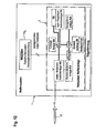
- Fig. 10 shows a structure of a virtual technical system consisting of a central computer simulator 20 S , which combines the functionalities of the individual component-specific central computer simulators, as well as from the corresponding component simulators 22 S , 23 S , 24 S , 25 S , 26 S.
- the central computer simulator 20 S and the component simulators 22 S , 23 S , 24 S , 25 S , 26 S are connected to each other via the data bus 27 for data exchange.
- the data bus - as in the example of Fig. 4 -
- the missile simulator 4 S The missile simulator 4 S , Plesystemspecialnsimulator 10 S and the bus monitor 28 'connected, which is provided with an evaluation.
- the flow and communication behavior of the real central computer can be simulated.
- the central computer simulator 20 S is thus, in contrast to the component-specific central computer simulators described so far able to test the behavior of the system with all connected components, so that with such a central computer simulator 20 S , for example, in the in Fig. 6 installed final acceptance structure of the integrated technical system is installed in place of the local central computer 20, the parallel communication and interaction behavior of the individual components against the central computer simulator 20 S can be tested.
- This integrated central computer simulator 20 S can therefore be used before starting the integration to check whether the delivered real technical components in the desired manner communicate in parallel with each other with the central computer simulator 20 S (and optionally with each other) in a correct manner.
- the in Fig. 10 It is also possible to verify on the part of the system integrator, before the delivery of the real components designed test procedures (for example, the input analysis of individual components, the test of the central computer or other system checks). This allows the system integrator Develop and verify appropriate test specifications long before the arrival of the real components.
- the simulation set-up can be used to verify and verify the correct functioning of data recording and evaluation tools used in later tests.
- this simulation setup can be used to test the behavior of software updates before these updates are imported into the central computer of the real system.
- This in Fig. 10 illustrated virtual system can also be used as a simulator of the entire subsystem weapon system with the other components of the in Fig. 1 shown weapon system, such as the weapon system headquarters, for data exchange (for example, via radio) to be connected to check the interaction of the weapons system center with the subsystem weapon system.
- weapon system such as the weapon system headquarters
- data exchange for example, via radio
- the component simulators Following the release of the interface definition between the individual components and the host and in parallel with the development of the individual components of the overall system, the component simulators, the component-specific central computer simulators, the integrated central computer simulator and the data recording and monitoring tools are implemented. As a result, these test and test devices are already available for engineering tests during the production of the individual components.
- the functional check of the data flows and processes specified in the interface definition is carried out by means of the in Fig. 10 represented and consisting of simulators virtual technical system. If deficits are found in these preliminary tests, corrections can be made both in the interface definition and in the functioning of the simulators be made.
- the integration test specifications are determined by means of the in Fig. 10
- the virtual system that is to be used for the component input checks, the check of the central computer and for the system checks is checked. Here, too, if necessary, a correction of the integration test regulations can be made.
- each component of the technical system is tested at the manufacturer of the component before delivery to the system integrator by the respective component-specific central computer simulator according to the relevant test specification. If the test result is negative, the system integrator refuses to accept the system and the errors found must first be remedied.
- the central computer is connected to the component simulators and tested according to the corresponding test specification. If there are functional problems, the in Fig. 10 shown virtual system as reference benchmark tests to establish the problem transparency. If necessary, the central computer should be troubleshooted. After the input of the central computer at the system integrator, an input detection is again carried out in the same way.
- the central computer is connected to the individual component simulators, and then one component simulator after another is gradually replaced by the corresponding real component, and after each stepwise replacement of a simulator by the respective real component, system checks are performed again Test regulations carried out. If technical problems of a component occur, the simulator operation is used as a reference. After replacing all component simulators with the corresponding component, only the weapon system center and missile simulators remain connected to the integrated system.
- the integration final acceptance takes place, whereby all functions of the current expansion stage of the technical system, in the example shown of the subsystem weapon system, including a complete remote-controlled shot sequence, are checked. Since no real weapons system center is available for this final acceptance test, it is simulated by the weapon system central simulator 10 S. The missile is also simulated by the missile simulator 4 S until the shot firing.
- Fig. 10 presented, consisting of simulators reference system instead of the example in the Fig. 10 provided weapon system central simulator 10 S connected by means of the wire-based data network with the real weapons system center 10 and the interaction between the weapons system center and the virtual subsystem weapons system is tested according to the test specifications. Only when this test is passed, the weapons system center 10 is connected to the real subsystem weapon system 2.
- the system check of the real subsystem Weapon System 2 takes place, whereby all functions of the current configuration stage of the subsystem including the complete remote controlled weft sequence are checked.
- the integrated subsystem weapon system 2 interacts radio-controlled with the weapon system center 10.
- the missile is still simulated by means of the missile simulator 4 S until the shot firing.
- a datalink communication between the Subsystem weapon system by means of a missile data link simulator 4 ' s checks as in Fig. 11 you can see.
- a real missile which is still in the transport and shot tank, attached to the missile elevation system 25 of the subsystem weapon system 2.
- the remote control and thus the firing by the weapon system central simulator 10 S which programmatically calculates the target and interception data and transmitted by means of the wire-based data network to the subsystem weapons system 2, which forwards this data radio-controlled to the flying missile 4 '.
- Fig. 12 which reproduces a program shot with a selectable target path simulation.
- a shot is made in the composite of the entire weapon system.
- other weapon system subsystems capture and measure the target.
- the weapon system center 10 remotely controls the weapon system 2 subsystem, triggers the shot, and transmits to the flying missile 4 'via weapon data link the interception and target data determined by the other weapon system subsystems.
- the component simulators, the component-specific central computer simulators and the integrated central computer simulator acquire a validated status, ie they have a communication and execution behavior that reliably represents the real components or the real central computer. If a component is to be replaced by another component (so-called "plug-and-fight" method), the new component can be validated against Simulators are developed and tested in installed and / or dismounted condition.
- simulatives which are iteratively improved and verified through these integration and testing steps, can then also be used for the production checks, namely for the component inward check, the central computer check, the weapons subassembly and subtraction.
- these simulators may be used as part of factory repair for the Weapons Receipt Inspection, post-repair check, or final Weapons Check before re-delivery to the user.
- the individual simulators are also suitable as a tool kit for field service repair.
- the military user can check the operational readiness of the weapon system subsystem by attaching the weapon system to the weapon system network using field and military-grade weapon system central simulators and missile simulators as part of an operational weapons system check.
Landscapes
- Engineering & Computer Science (AREA)
- Computer Hardware Design (AREA)
- General Engineering & Computer Science (AREA)
- Physics & Mathematics (AREA)
- General Physics & Mathematics (AREA)
- Theoretical Computer Science (AREA)
- Quality & Reliability (AREA)
- Automation & Control Theory (AREA)
- Management, Administration, Business Operations System, And Electronic Commerce (AREA)
- Test And Diagnosis Of Digital Computers (AREA)
- Debugging And Monitoring (AREA)
- Hardware Redundancy (AREA)
Applications Claiming Priority (1)
| Application Number | Priority Date | Filing Date | Title |
|---|---|---|---|
| DE102012006872A DE102012006872A1 (de) | 2012-04-04 | 2012-04-04 | Verfahren und Vorrichtung zur Integration von technischen Systemen |
Publications (2)
| Publication Number | Publication Date |
|---|---|
| EP2648103A2 true EP2648103A2 (fr) | 2013-10-09 |
| EP2648103A3 EP2648103A3 (fr) | 2017-03-29 |
Family
ID=48082805
Family Applications (1)
| Application Number | Title | Priority Date | Filing Date |
|---|---|---|---|
| EP13001509.2A Ceased EP2648103A3 (fr) | 2012-04-04 | 2013-03-25 | Procédé et dispositif d'intégration de systèmes techniques |
Country Status (2)
| Country | Link |
|---|---|
| EP (1) | EP2648103A3 (fr) |
| DE (1) | DE102012006872A1 (fr) |
Cited By (2)
| Publication number | Priority date | Publication date | Assignee | Title |
|---|---|---|---|---|
| EP2869143A1 (fr) * | 2013-10-30 | 2015-05-06 | Siemens Aktiengesellschaft | Système d'émulation pour la simulation d'un système technique |
| EP2980661A1 (fr) | 2014-07-30 | 2016-02-03 | Siemens Aktiengesellschaft | Appareil de commande électronique |
Families Citing this family (2)
| Publication number | Priority date | Publication date | Assignee | Title |
|---|---|---|---|---|
| DE102016008413A1 (de) | 2016-07-13 | 2018-01-18 | Mbda Deutschland Gmbh | Multifunktionsbedien- und Anzeigesystem |
| DE102016219208A1 (de) * | 2016-10-04 | 2018-04-05 | Mbda Deutschland Gmbh | Verfahren zum bereitstellen einer gesicherten kommunikationsverbindung zwischen komponenten einer sicherheitskritischen funktionskette |
Citations (2)
| Publication number | Priority date | Publication date | Assignee | Title |
|---|---|---|---|---|
| EP1659468A2 (fr) * | 2004-11-16 | 2006-05-24 | Rockwell Automation Technologies, Inc. | Interface d'exécution universelle pour simulation à base d'agent et systèmes de contrôle |
| US20100017191A1 (en) * | 2007-02-15 | 2010-01-21 | Fujitsu Ten Limited | Microcomputer simulator |
Family Cites Families (2)
| Publication number | Priority date | Publication date | Assignee | Title |
|---|---|---|---|---|
| DE102007029137B4 (de) * | 2007-06-25 | 2013-04-18 | Airbus Operations Gmbh | Testsystem-Verbund zum parallelen Testen mehrerer Systeme unter Test mit mehreren Testsystemen |
| FR2950449A1 (fr) * | 2009-09-23 | 2011-03-25 | Eurocopter France | Simulation en temps reel hautement representative d'un systeme avionique |
-
2012
- 2012-04-04 DE DE102012006872A patent/DE102012006872A1/de not_active Withdrawn
-
2013
- 2013-03-25 EP EP13001509.2A patent/EP2648103A3/fr not_active Ceased
Patent Citations (2)
| Publication number | Priority date | Publication date | Assignee | Title |
|---|---|---|---|---|
| EP1659468A2 (fr) * | 2004-11-16 | 2006-05-24 | Rockwell Automation Technologies, Inc. | Interface d'exécution universelle pour simulation à base d'agent et systèmes de contrôle |
| US20100017191A1 (en) * | 2007-02-15 | 2010-01-21 | Fujitsu Ten Limited | Microcomputer simulator |
Cited By (2)
| Publication number | Priority date | Publication date | Assignee | Title |
|---|---|---|---|---|
| EP2869143A1 (fr) * | 2013-10-30 | 2015-05-06 | Siemens Aktiengesellschaft | Système d'émulation pour la simulation d'un système technique |
| EP2980661A1 (fr) | 2014-07-30 | 2016-02-03 | Siemens Aktiengesellschaft | Appareil de commande électronique |
Also Published As
| Publication number | Publication date |
|---|---|
| EP2648103A3 (fr) | 2017-03-29 |
| DE102012006872A1 (de) | 2013-10-10 |
Similar Documents
| Publication | Publication Date | Title |
|---|---|---|
| EP2801873B1 (fr) | Dispositif de test d'un appareil de commande virtuel | |
| EP2770389B1 (fr) | Procédé de réalisation d'une configuration d'un système de test d'appareils de commande | |
| EP3614154B1 (fr) | Système de faisceaux de câbles et procédé de vérification de faisceaux de câbles | |
| EP3987373B1 (fr) | Analyse efficace d'erreurs au moyen des erreurs simulées dans un double numérique | |
| DE102007010978A1 (de) | Verfahren und Vorrichtung zur Unterstützung einer Diagnose eines elektrischen Systems mittels wahrscheinlichkeitsbasierter Fehlerkandidatenermittlung | |
| EP1923658B2 (fr) | Procédé de vérification de la capacité d'interaction entre un aéronef et un corps volant non habité armé pouvant être couplé avec celui-ci | |
| EP2293008A2 (fr) | Dispositif de commande de tests fonctionnels et/ou de procédures de service pour aéronefs sans conducteur pouvant être déposés par des avions | |
| DE102014101321A1 (de) | Testeinrichtung zum Test eines virtuellen Steuergeräts | |
| EP2648103A2 (fr) | Procédé et dispositif d'intégration de systèmes techniques | |
| EP2381206B1 (fr) | Procédé de détection d'erreur d'un véhicule volant non habité accouplé à un avion porteur en vol et véhicule volant non habité | |
| EP3270092B1 (fr) | Véhicule d'opération militaire avec système d'affichage et de commande multifonctions | |
| DE102011000958A1 (de) | Verfahren und System zum Testen von Software und/oder Hardware eines oder mehrerer in ein Kraftfahrzeug zu integrierender Bauteile | |
| EP1295519B1 (fr) | Procede de fabrication d'un appareil electronique | |
| DE102021206985A1 (de) | System zur Verarbeitung von Daten | |
| EP1795858A1 (fr) | Unité de test de station d'armement et procédé pour tester la disponibilité d'une station d'armement d'un aéronef | |
| DE102009009293A1 (de) | Verfahren und System zum Engineering einer Automatisierung zumindest eines Teils einer technischen Anlage | |
| EP1866715B1 (fr) | Système de conception pour concevoir un système de commande et une méthode pour examiner la tâche technologique du système de commande pendant la conception du dit système de commande | |
| WO2015180932A1 (fr) | Procédé de test informatisé d'un système technique | |
| WO1999038024A1 (fr) | Procede d'optimisation de specifications de controle et de minimisation de logiciels de controle assistees par ordinateur | |
| WO2006081869A1 (fr) | Dispositif et procede pour tester des composantes et des systemes | |
| EP1984750A1 (fr) | Procédé et dispositif permettant de tester un appareil de protection traitant des données échantillonnées numériques | |
| DE102006015207A1 (de) | Verfahren und Vorrichtung zur Entwicklung eines Systems für die Betriebsdiagnostik von Fahrzeugen | |
| DE102024129697A1 (de) | System, Verwendung eines Systems und Verfahren zum Testen einer Firmware eines Microcontrollers für ein eingebettetes System | |
| DE102015209341A1 (de) | Agent zur Koordination einer von mindestens einer Applikationsverteilereinrichtung ausgehenden Verteilung von wenigstens einer Softwareeinheit und zugehöriges Betriebsverfahren | |
| WO2020015837A1 (fr) | Procédé et agencement permettant de produire, vérifier et optimiser un programme d'automatisation |
Legal Events
| Date | Code | Title | Description |
|---|---|---|---|
| PUAI | Public reference made under article 153(3) epc to a published international application that has entered the european phase |
Free format text: ORIGINAL CODE: 0009012 |
|
| AK | Designated contracting states |
Kind code of ref document: A2 Designated state(s): AL AT BE BG CH CY CZ DE DK EE ES FI FR GB GR HR HU IE IS IT LI LT LU LV MC MK MT NL NO PL PT RO RS SE SI SK SM TR |
|
| AX | Request for extension of the european patent |
Extension state: BA ME |
|
| PUAL | Search report despatched |
Free format text: ORIGINAL CODE: 0009013 |
|
| AK | Designated contracting states |
Kind code of ref document: A3 Designated state(s): AL AT BE BG CH CY CZ DE DK EE ES FI FR GB GR HR HU IE IS IT LI LT LU LV MC MK MT NL NO PL PT RO RS SE SI SK SM TR |
|
| AX | Request for extension of the european patent |
Extension state: BA ME |
|
| RIC1 | Information provided on ipc code assigned before grant |
Ipc: G06F 11/26 20060101ALI20170220BHEP Ipc: G06F 11/22 20060101AFI20170220BHEP |
|
| STAA | Information on the status of an ep patent application or granted ep patent |
Free format text: STATUS: REQUEST FOR EXAMINATION WAS MADE |
|
| 17P | Request for examination filed |
Effective date: 20170504 |
|
| STAA | Information on the status of an ep patent application or granted ep patent |
Free format text: STATUS: EXAMINATION IS IN PROGRESS |
|
| 17Q | First examination report despatched |
Effective date: 20181012 |
|
| STAA | Information on the status of an ep patent application or granted ep patent |
Free format text: STATUS: THE APPLICATION HAS BEEN REFUSED |
|
| 18R | Application refused |
Effective date: 20190628 |