EP2653429B1 - Procédé de commande pour chariot de manutention et chariot de manutention - Google Patents
Procédé de commande pour chariot de manutention et chariot de manutention Download PDFInfo
- Publication number
- EP2653429B1 EP2653429B1 EP20130162430 EP13162430A EP2653429B1 EP 2653429 B1 EP2653429 B1 EP 2653429B1 EP 20130162430 EP20130162430 EP 20130162430 EP 13162430 A EP13162430 A EP 13162430A EP 2653429 B1 EP2653429 B1 EP 2653429B1
- Authority
- EP
- European Patent Office
- Prior art keywords
- load
- control method
- pickup means
- functions
- industrial truck
- Prior art date
- Legal status (The legal status is an assumption and is not a legal conclusion. Google has not performed a legal analysis and makes no representation as to the accuracy of the status listed.)
- Active
Links
Images


Classifications
-
- B—PERFORMING OPERATIONS; TRANSPORTING
- B66—HOISTING; LIFTING; HAULING
- B66F—HOISTING, LIFTING, HAULING OR PUSHING, NOT OTHERWISE PROVIDED FOR, e.g. DEVICES WHICH APPLY A LIFTING OR PUSHING FORCE DIRECTLY TO THE SURFACE OF A LOAD
- B66F9/00—Devices for lifting or lowering bulky or heavy goods for loading or unloading purposes
- B66F9/06—Devices for lifting or lowering bulky or heavy goods for loading or unloading purposes movable, with their loads, on wheels or the like, e.g. fork-lift trucks
- B66F9/075—Constructional features or details
- B66F9/0755—Position control; Position detectors
-
- B—PERFORMING OPERATIONS; TRANSPORTING
- B66—HOISTING; LIFTING; HAULING
- B66F—HOISTING, LIFTING, HAULING OR PUSHING, NOT OTHERWISE PROVIDED FOR, e.g. DEVICES WHICH APPLY A LIFTING OR PUSHING FORCE DIRECTLY TO THE SURFACE OF A LOAD
- B66F9/00—Devices for lifting or lowering bulky or heavy goods for loading or unloading purposes
- B66F9/06—Devices for lifting or lowering bulky or heavy goods for loading or unloading purposes movable, with their loads, on wheels or the like, e.g. fork-lift trucks
- B66F9/075—Constructional features or details
- B66F9/20—Means for actuating or controlling masts, platforms, or forks
- B66F9/24—Electrical devices or systems
Definitions
- the invention relates to a control method for an industrial truck with at least one camera, a monitor and a control device aligned with the area of a lifting device, wherein in the control method, when the truck with the load handling device is in front of a load to be picked up, the steps detect the load by means of image processing methods by the control device, such as pattern or object detection, locating a load transfer device of the load by the control device, determining the relative position of the load transport device to the load receiving means and the relative position of the receiving elements of the load transport device, which are provided for the load handling means of the truck by the control device be performed.
- image processing methods such as pattern or object detection
- Forklift trucks and reach trucks are used in addition to pallet trucks to a very large extent as industrial trucks, these types of industrial trucks mainly transporting loads arranged on pallets.
- two forks are usually arranged to form a fork on a fork carriage with which in the recording of a load by appropriate maneuvering of the forklift and driving a mast on which the fork is guided vertically movable, associated receiving openings of a pallet can be controlled.
- unfavorable visibility conditions such as at very high lifted fork or in poorly lit areas of a warehouse, this can be tedious or at least require considerable time, as must be particularly slow and carefully controlled.
- the handling capacity and the efficient use of industrial trucks are also impaired by the fact that drivers or operators of industrial trucks may not yet have sufficient training in the operation and in the control of the truck.
- the load-receiving device and optionally located in front of or on the load-receiving device transport with load, such as a loaded pallet, and at the same time on a monitor.
- load such as a loaded pallet
- monitor can also map the environment of the truck while driving very general and represent.
- Primary fields of application here are load-bearing at high lifting heights and driving in restricted visibility conditions, especially reverse driving and driving forward in the event of visual obstruction due to the load being picked up.
- Driverless transport systems are also known in which image data obtained by a camera are used to generate control commands to the vehicle control system.
- Optical sensors are now available in very compact dimensions and cost just as miniaturized cameras, z. B. for widespread use in mobile phones. Also, by using a plurality of optical sensors within a housing, the imaging range can be increased or three-dimensional data can be obtained by combining the sensor data of the individual sensors. In addition, image-sensor combinations are available in the field of the video entertainment industry. In addition to imaging camera sensors, they can use correlated depth-measuring sensor systems to provide three-dimensional image data.
- From the DE 10 2008 027 701 A1 is a control method for an autonomous, fully automatic truck with a laser sensor in the area of the lifting device known. From data of the sensor, the relative position of a load to be absorbed relative to a load-receiving means can be determined by a control device and subsequently the desired orientation of the load-receiving means for receiving the load can be calculated. The actual orientation of the load receiving means is fully automatically corrected by the control device.
- the EP0800129A1 discloses an industrial truck, which is designed to be either manually or automatically operable.
- the control system is designed to automatically manage the movements of pallets.
- the present invention has for its object to provide a control method for an industrial truck and an associated truck available with the ease of use for inexperienced with the operation people and with the handling capacity of the truck can be increased.
- the handling performance and the efficient use of industrial trucks can be increased if an operator is still relatively inexperienced in the operation of the truck.
- Especially the reliable and safe picking up of a load without damaging the load or other objects in the vicinity requires some practice and can only be carried out with greater speed after some routine. This is especially true when the load is, for example, in a high rack in a higher storage position.
- the load is, for example, in a high rack in a higher storage position.
- control commands of the truck operator such as a reach truck or even a counterbalance forklift or Gabelhochhubwagens, in a different manner, as in a position close to the ground.
- vibrations and delays can occur due to the elasticity of a lifting mast.
- control device has determined a sequence of control commands of the functions of the lifting device and optionally of driving the truck to the load receiving means, such as a fork with the forks, in the receiving elements of a load handling device for the load, such as a pallet with the provided for the forks openings To move, these recording elements on the monitor, but alternatively also on another suitable, possibly already existing display device of the truck, marked marked.
- the automatic control of the functions or driving movement takes place only after the control device receives a signal that a confirmation input has been made by the driver.
- Such a confirmation input may be a dedicated switch, a button on the touch-sensitive monitor, or any other suitable operator-aware input.
- the control device performs those necessary movements to move the load receiving means in the receiving elements, which can be made as movements of the control device automatically.
- the functions of a lifting device by working hydraulics the valves are usually carried out as electrically actuated control valves, with manually performed operating inputs via controls that emit an electrical signal. This allows a fully automatic control by the control device in the method according to the invention, which is inexpensive to implement.
- the values to be set for the operating element are displayed by a graphical display on the monitor, but also optionally in another alternative display option.
- This can be, for example, turns of a steering wheel, but also an arrow-controlled display which specifies in which direction a control element is to be actuated until the value to be set is reached.
- this is also possible for operating lever for a lifting height, a side thrust, a mast thrust, a tilt of the lifting device or a mast tilt.
- functions that could be controlled fully automatically by the control device are operated in this way.
- a human control both in terms of the correct determination of an intended automated movement sequence and during the automated movement sequence of the truck. Therefore, safety requirements can be met more easily and a required greater effort as in autonomous industrial trucks can be avoided.
- the method is also inexpensive to implement insofar as already exists for a variety of functions of the load-handling device as well as the driving functions of the truck automatic control and for the remaining required functions such is not required.
- control of a brake pedal and an accelerator pedal may remain under human control alone.
- the load transport device is a pallet and the receiving elements openings for forks of a fork as a load-receiving element.
- the edges of the load and / or the edges of the load transport device are detected by the control device.
- the load transport device can be found in an image pattern, which must be located at the lower end of these edges.
- the load can also be completely enclosed by the load transport device, as in the case of a mesh basket, in which the load transport device is already detected by the detection of the load, as a rule.
- one or more further confirmation inputs before or between the activation of individual functions of the lifting device and / or the Control of individual driving functions of the truck are queried.
- the automated control of individual functions of the load handling device and / or individual driving functions of the truck can be done simultaneously, but also for time optimization simultaneously. Moreover, at the same time the control of those functions by the operator can take place, which can not be controlled automatically. It can be provided that further confirmation inputs must be made in the same manner described above, in order to meet safety requirements, for example, if in a certain automated movements increased monitoring by the operator should be ensured.
- a continuous confirmation input is interrogated and, in the absence of a confirmation signal, the control of the functions of the load receiving means and / or the driving functions of the truck is stopped.
- a confirmation input can also be provided by the fact that a corresponding signal must be given constantly and when a "release” all automated movements are stopped.
- the lifting device may be guided vertically movable on a mast and functions of the lifting device may be the lifting height and / or a slope and / or a mast thrust of the mast.
- the inventive method is particularly advantageous when loads must be taken even at high altitudes, as it can cause vibrations and elastic deformation of the mast at high lifting heights, which can complicate the operation in addition. In particular, however, the visibility at high lift are unfavorable.
- the inventive method supports as an assistance system an operator in contrast, for example, to a pure camera system according to the prior art in the operation and thus avoids the problems that can occur when an operator only on the basis of a camera image movements of Lifting means must control.
- One function of the load handling device may be a side thruster.
- the load-carrying means is a fork and a function of the load-carrying means a fork tine adjustment.
- a quick lateral alignment of the forks and rapid adjustment of the distance between the forks will be beneficial to the handling capacity of the truck.
- the display of values to be set for functions of the load-handling device and for driving functions of the truck on the monitor takes place continuously until the load-receiving means is located in the receiving elements.
- a value range of a required steering angle is displayed for the steering angle as the driving function of the truck as the value to be set, as well as the actual value of the steering angle.
- the inventive method does not require autonomous steering with the appropriate requirements for safety and reliability.
- the load-carrying means may be a fork and be displayed on the monitor, the way the forks in the receiving elements of the load transport device.
- Such a representation allows an intuitive check by the operator as to whether there is a risk of collisions.
- a warning tone and / or the further control of the functions of the load-handling device and / or the driving functions of the truck is stopped.
- optical sensors for the detection of the load, which are connected to the control device.
- optical sensors By further optical sensors, the accuracy of detection can be improved.
- Such optical sensors are available as CMOS image sensors but also as miniaturized cameras inexpensively as mass products.
- the further optical sensors can preferably, in addition to the already mentioned image information, for example encoded in brightness and color values of the pixels, acquire further information, such as distance information in the form of point clouds.
- a stereo image can be obtained in general by two cameras, from which information about the distance of the individual pixels can be obtained.
- the camera can be a Time Of Flight camera.
- the camera is a stereo camera.
- a stereo camera can be very compact in a camera win a double image, from which a distance information can be calculated.
- the camera is arranged on a fork carrier of the load-receiving means, in particular arranged so as to be movable in height, and can be moved to a position below the load-carrying means.
- the camera on a vertical rail behind the load bearing device preferably designed as a load fork on the fork carriage in height be arranged so that it can be moved at a load lying on the load fork down until the camera is a field of vision under the forks Reached fork. It is also possible to generally move the camera in this lower position for the image recording in the inventive method.
- movable cameras that can not be moved vertically but horizontally.
- the monitor can be a touch screen.
- the inventive method is also applicable when a load handling device carries no load, such as when a single empty pallet is picked up without load. In such a case, the image processing must be adjusted accordingly so that the pattern of an empty load transporting device without load is recognized.
- the method according to the invention can also be modified insofar as there is no search for an actual load.
- an industrial truck having at least one camera, a monitor and a control device, which is aligned with the region of a load-receiving device and in which the control device carries out a method described above.
- the truck has the advantages already described above.
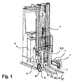
- a truck is shown in perspective view, in which the control method according to the invention is used.
- the truck is a reach truck with a first Radarm 1 with a roller 2 and a second Radarm 3, also with a roller 2.
- the inventive method is at any time in any other type of truck and especially forklift, such as a Counterbalance forklift, or about a Gabelhochhubwagen used.
- the control method according to the invention can also be used in industrial trucks that have no mast.
- a fork carriage 11 is arranged on a lifting mast 4, to which a load fork 5 is attached as a load-receiving means 9. Behind the mast 4, a battery 6 is arranged.
- the load carrier 5 carrying fork carriage 11 is raised and lowered on the mast 4 by means of a lifting drive.
- the mast 4 can be moved forward between the wheel arms 1, 3 to receive a load.
- a first fender 7 and the roller 2 of the second Radarms 3 also a second fender 8.
- a camera 10 is arranged at the fork carriage 11.
- the camera 10 is arranged in the vehicle transverse direction in the central region of the fork carriage 11.
- the camera 10 is preferably arranged in height adjustable on the fork carriage 11 and can be moved to a position below the fork 5.
- a miniature camera 13 can be arranged as a further optical sensor 14 on a fork tine 12. Such miniature cameras 13 are available in robust and cost-effective design and are used for example in numerous mobile phones.
- the Fig. 2 schematically shows the truck according to the invention in view from above.
- the fork 5 Between the first Radarm 1 and the second Radarm 3 with the roller 2 of the mast 4 is arranged with the fork 5.
- the camera 10 On the fork carriage 11 with the fork 5, the camera 10 is arranged, which detects with its detection area 17 located in front of the forks 5 as a load-receiving means 9 load 15.
- a control device not shown detects from the image data of the camera 10, the relative, in the example twisted arrangement of the load 15 and pallet 16.
- the Fig. 3 shows a perspective view of the male load 15 on a pallet 16 as a load transport device 18.
- the control device searches for characteristic points on load 15 and load transport device 18, preferably vertical edges 19 of the load 15 by means of image processing methods, by means of which the respective ends of the load transport device 18 can be found , Based on these edges 19, the transport device 18 is searched at the respective lower end. Based on edges 20 of the contour of the load transport device 18, here the pallet 16, their position and relative orientation is determined. As a result, openings 21 of the pallet 16, which serve for receiving the fork tines 12 of the forks 5 and forming receiving elements 22 for the load-receiving means 9 of the industrial truck, can be found.
- the Fig. 4 shows a monitor image of a monitor 23, which is arranged in the field of view of the operator of the truck.
- On this monitor image is a section of the captured by the camera 10 representation of the load 15 with the load transport device 18 in the form of a pallet 16 from the Fig. 3 displayed.
- the arrows 21 indicate the openings 21 identified by the control device corresponding to the receiving elements 22 for the load-receiving means 9 of the industrial truck.
- An operator of the truck can now confirm the correct recognition of the openings 21 and by a confirmation input, for example by a switch not shown here or a control panel 24 of the touchscreen 25 designed as a monitor 23, the automatic control of the functions of the lifting device 9 and the driving functions of Start the truck.
- a value to be set is displayed on the monitor 23 for functions that can not be controlled automatically, in the present case the steering of the industrial truck.
- the load fork 5 aligns with the openings 21 and, when the operator observes the appropriate instructions about the values to be set, the forks 12 of the forks 5 enter the openings 21.
- This assistance function also allows operators with little experience to safely receive a load 15 together with a load transport device 18.
- the control device may be integrated in a control computer of the vehicle or consist entirely or in part from a separate computer.
- the Fig. 5 shows a schematic of the method according to the invention.
- the monitor 23 may consist of any form of image display means, e.g. B. a color screen in LCD technology.
- the functions 26 of the load-receiving means 9 are controlled by the operator in normal operation via working hydraulic control elements 27 and are usually made of hydraulic elements, which are usually automatically controlled by electrically controllable valves.
- Via a traction drive control 28 of the driving functions 29 of the truck an operator is able to control the vehicle movement.
- An image processing unit 30 forms part of a control device 31, which can detect and process the signals of one or more optical sensors 10, 14 in real time.
- An optical sensor in the present example case, the camera 10 and the optical sensor 14 in the Fig. 1
- the optical sensors 10, 14 are able to record brightness and color information by, for example, a camera chip and can, with appropriate design, also determine distances to objects by optical means.
- the functions 26 of the load receiving means 9 and the driving functions 29 of the truck are in the illustration of Fig. 5 to vehicle drives 32 summarized.
- the working hydraulic control elements 27, the traction drive control 28 and the monitor 23 are arranged in the area of a driver's workplace 33.
- the image processing unit 30 and the optical sensors 10, 14 are arranged in the region of the load-receiving means 9, here the fork carrier 11 and the fork tine 12.
- a vehicle controller 34 in the present example also forms part of the control device 31 and connects the aforementioned elements via unidirectional or bidirectional communication means.
- the image processing unit 30 can also be arranged elsewhere and / or also integrated into the vehicle control system 34, so that the vehicle control system 34 simultaneously forms the complete control device 31 of the embodiment described above.
- a signal S1 transmits an acknowledgment signal, which is generated when the operator confirms the confirmation input, as well as other selection and control signals.
- the signal S2 transmits the image of the camera 10, the quality of which can be improved by image processing algorithms of the control device 31 and which can additionally be provided with superimposed algorithmically generated additional information, e.g. B. distance information, route specifications and markings of hazardous areas.
- the signal S3 includes control signals of the working hydraulic controls 27 and the signal S4 control signals of the traction drive operation 28.
- the signal S5 is the image information signal of the camera 10 and the signal S6 is the image information signal of the optical sensor 14.
- Generated control signals of the image processing unit 30 are transmitted to the vehicle controller 34 via a signal S7.
- a signal S8 forms the control signals of the functions 26 of the load receiving means 9 and a signal S9 is used to control the driving functions 29th
Landscapes
- Engineering & Computer Science (AREA)
- Transportation (AREA)
- Structural Engineering (AREA)
- Civil Engineering (AREA)
- Life Sciences & Earth Sciences (AREA)
- Geology (AREA)
- Mechanical Engineering (AREA)
- Chemical & Material Sciences (AREA)
- Combustion & Propulsion (AREA)
- Forklifts And Lifting Vehicles (AREA)
Claims (18)
- Procédé de commande pour un chariot de manutention avec au moins une caméra (10) orientée vers la zone d'un moyen de réception de charge (9), un écran (23) et un dispositif de commande (31), dans lequel procédé de commande, lorsque le chariot de manutention avec le moyen de réception de charge (9) se trouve devant une charge à réceptionner (15), les étapes suivantes sont mises en oeuvre :- détection de la charge (15), par le dispositif de commande (31), au moyen d'un procédé de traitement d'images tel que par exemple une reconnaissance de motif ou d'objet,- recherche, par le dispositif de commande (31), d'un dispositif de transport de charge (18) de la charge (15),- détermination de la position relative du dispositif de transport de charge (18) par rapport au moyen de réception de charge (9) et de la position relative des éléments de logement (22) du dispositif de transport de charge (18), lesquels sont prévus pour le moyen de réception de charge (9) du chariot de manutention, grâce au dispositif de commande (31),- représentation à l'écran (23) de parties au moins de la charge (15) ainsi que des éléments de logement (22),- marquage des éléments de logement (22) dans la représentation à l'écran (23),- appel sélectif d'une saisie de confirmation (S1),- en cas d'une saisie de confirmation (S1), réception de la charge (15) sur le moyen de réception de charge (9) grâce à un réglage et à une orientation automatiques des fonctions (26) - pouvant être commandées par le dispositif de commande (31) - du moyen de réception de charge et des fonctions de marche (29) - pouvant être commandées par le dispositif de commande (31) - du chariot de manutention, et- affichage à l'écran (23) de valeurs à régler pour des fonctions (26) du moyen de réception de charge et des fonctions de marche (29) du chariot de manutention, lesquelles ne peuvent pas être automatiquement commandées par le dispositif de commande (31).
- Procédé de commande selon la revendication 1, caractérisé en ce que le dispositif de transport de charge (18) est une palette (16) et les éléments de logement (22) sont des ouvertures (21) pour des dents de fourche (12) d'une fourche de levage (5) en tant qu'élément de réception de charge (9).
- Procédé de commande selon la revendication 1 ou 2, caractérisé en ce que le dispositif de commande détecte les arêtes (19) de la charge (15) et/ou les arêtes (20) du dispositif de transport de charge (18).
- Procédé de commande selon l'une des revendications 1 à 3, caractérisé en ce qu'une ou plusieurs autres saisies de confirmation sont appelées sélectivement avant ou entre la commande de fonctions individuelles (26) du moyen de réception de charge et/ou la commande de fonctions de marche (29) individuelles du chariot de manutention.
- Procédé de commande selon l'une des revendications 1 à 4, caractérisé en ce que l'on appelle sélectivement une saisie de confirmation persistante et en ce que, en cas d'absence d'un signal de confirmation, on interrompt la commande des fonctions (26) du moyen de réception de charge et/ou des fonctions de marche (29) du chariot de manutention.
- Procédé de commande selon l'une des revendications 1 à 5, caractérisé en ce que le moyen de réception de charge (9) est guidé de manière déplaçable en hauteur sur un mât de levage (4), et des fonctions (26) du moyen de réception de charge sont la hauteur de levage et/ou une inclinaison et/ou une poussée de mât du mât de levage (4).
- Procédé de commande selon l'une des revendications 1 à 6, caractérisé en ce qu'une fonction (26) du moyen de réception de charge est un dispositif de poussée latérale.
- Procédé de commande selon l'une des revendications 1 à 7, caractérisé en ce que le moyen de réception de charge (9) est une fourche de levage (5) et une fonction du moyen de réception de charge (9) est un déplacement de dents de fourche.
- Procédé de commande selon l'une des revendications 1 à 8, caractérisé en ce que l'affichage à l'écran (23) de valeurs à régler pour des fonctions (26) du moyen de réception de charge (9) et pour des fonctions de marche (29) du chariot de manutention s'effectue en continu jusqu'à ce que le moyen de réception de charge (9) se trouve dans les éléments de logement (22).
- Procédé de commande selon la revendication 9, caractérisé en ce que, pour l'angle de direction - en tant que fonction de marche (29) du chariot de manutention - en tant que valeur à régler, on affiche une plage de valeurs d'un angle de braquage nécessaire ainsi que la valeur réelle de l'angle de braquage.
- Procédé de commande selon la revendication 10, caractérisé en ce que le moyen de réception de charge (9) est une fourche de levage (5) et l'on représente à l'écran (23) le trajet des dents de fourche (12) dans les éléments de logement (22) du dispositif de transport de charge (18).
- Procédé de commande selon l'une des revendications 1 à 11, caractérisé en ce que, en cas de reconnaissance d'un risque de collision, il y a un avertissement sonore et/ou la suite de la commande des fonctions (26) du moyen de réception de charge (9) et/ou des fonctions de marche (29) du chariot de manutention est interrompue.
- Procédé de commande selon l'une des revendications 1 à 12, caractérisé en ce que l'on prévoit d'autres capteurs optiques (14) pour la détection de la charge (15), lesquels sont en liaison avec le dispositif de commande (31).
- Procédé de commande selon l'une des revendications 1 à 13, caractérisé en ce que la caméra (10) est une caméra Time Of Flight.
- Procédé de commande selon l'une des revendications 1 à 13, caractérisé en ce que la caméra (10) est une caméra stéréo.
- Procédé de commande selon la revendication 14 ou 15, caractérisé en ce que la caméra (10) est disposée sur un porte-fourche (11) du moyen de réception de charge (9), en particulier peut être disposée de manière déplaçable en hauteur, et peut être déplacée dans une position en dessous du moyen de réception de charge (9).
- Procédé de commande selon l'une des revendications 1 à 16, caractérisé en ce que l'écran (23) est un écran tactile (25).
- Chariot de manutention avec au moins une caméra (10) orientée vers la zone d'un moyen de réception de charge (9), un écran (23) et un dispositif de commande (31), lequel met en oeuvre un procédé selon l'une des revendications 1 à 14.
Applications Claiming Priority (3)
| Application Number | Priority Date | Filing Date | Title |
|---|---|---|---|
| DE102012103485 | 2012-04-20 | ||
| DE102012103840 | 2012-05-02 | ||
| DE201210108034 DE102012108034A1 (de) | 2012-04-20 | 2012-08-30 | Steuerungsverfahren für Flurförderzeug sowie Flurförderzeug |
Publications (2)
| Publication Number | Publication Date |
|---|---|
| EP2653429A1 EP2653429A1 (fr) | 2013-10-23 |
| EP2653429B1 true EP2653429B1 (fr) | 2015-03-25 |
Family
ID=48050502
Family Applications (1)
| Application Number | Title | Priority Date | Filing Date |
|---|---|---|---|
| EP20130162430 Active EP2653429B1 (fr) | 2012-04-20 | 2013-04-05 | Procédé de commande pour chariot de manutention et chariot de manutention |
Country Status (2)
| Country | Link |
|---|---|
| EP (1) | EP2653429B1 (fr) |
| DE (1) | DE102012108034A1 (fr) |
Cited By (6)
| Publication number | Priority date | Publication date | Assignee | Title |
|---|---|---|---|---|
| DE102017124850A1 (de) | 2017-10-24 | 2019-04-25 | Jungheinrich Ag | Flurförderzeug mit einer Gabel und einer Gabelzinkenkamera sowie Verfahren zum Betreiben eines solchen Flurförderzeugs |
| US10430073B2 (en) | 2015-07-17 | 2019-10-01 | Crown Equipment Corporation | Processing device having a graphical user interface for industrial vehicle |
| US10754466B2 (en) | 2016-11-22 | 2020-08-25 | Crown Equipment Corporation | User interface device for industrial vehicle |
| WO2020229593A1 (fr) | 2019-05-16 | 2020-11-19 | Jungheinrich Ag | Procédé d'assistance au stockage dans un chariot de manutention et chariot de manutention |
| DE102019113606A1 (de) * | 2019-05-22 | 2020-11-26 | Jungheinrich Ag | Flurförderzeug mit Kamerasystem |
| US11591197B2 (en) | 2019-04-05 | 2023-02-28 | The Raymond Corporation | Load handling module for a material handling vehicle |
Families Citing this family (11)
| Publication number | Priority date | Publication date | Assignee | Title |
|---|---|---|---|---|
| AU2014277738B2 (en) | 2013-12-19 | 2020-04-30 | The Raymond Corporation | Integrated touch screen display with multi-mode functionality |
| US9932213B2 (en) | 2014-09-15 | 2018-04-03 | Crown Equipment Corporation | Lift truck with optical load sensing structure |
| DE102016119402A1 (de) | 2016-10-12 | 2018-04-12 | Jungheinrich Aktiengesellschaft | Flurförderzeug mit einer 3D-Kamera |
| DE102017116625A1 (de) * | 2017-07-24 | 2019-01-24 | Still Gmbh | Flurförderzeug |
| DE102017116626A1 (de) * | 2017-07-24 | 2019-01-24 | Still Gmbh | Flurförderzeug |
| DE102019109007A1 (de) | 2019-04-05 | 2020-10-08 | Jungheinrich Ag | Flurförderzeug und Verfahren zum Betreiben desselben |
| CN111908383B (zh) * | 2020-08-18 | 2023-07-18 | 诺力智能装备股份有限公司 | 一种托盘联动校准装置及方法 |
| CN113177431B (zh) * | 2021-03-15 | 2023-12-08 | 福建电子口岸股份有限公司 | 一种基于机器视觉和深度学习的集卡防吊起方法、系统 |
| DE102022130297A1 (de) | 2022-11-16 | 2024-05-16 | Still Gesellschaft Mit Beschränkter Haftung | Flurförderzeug und Verfahren zum Betreiben eines Flurförderzeugs |
| DE102023125122A1 (de) * | 2023-09-18 | 2025-03-20 | Jungheinrich Aktiengesellschaft | Bestimmung einer Hubhöhe oder -geschwindigkeit eines Lasttragmittels |
| DE102024114325A1 (de) * | 2024-05-22 | 2025-11-27 | Jungheinrich Aktiengesellschaft | Verfahren zur Bestimmung der Pose einer Palette relativ zu einem Flurförderzeug und Flurförderzeug |
Family Cites Families (4)
| Publication number | Priority date | Publication date | Assignee | Title |
|---|---|---|---|---|
| DE19613386A1 (de) * | 1996-04-03 | 1997-10-09 | Fiat Om Carrelli Elevatori | Flurförderzeug, das wahlweise manuell oder automatisch betreibbar ausgebildet ist |
| WO2003062127A1 (fr) * | 2002-01-23 | 2003-07-31 | Kabushiki Kaisha Toyota Jidoshokki | Dispositif et procede de commande de la position d'un appareil de manutention dans un vehicule industriel |
| DE102006012205A1 (de) | 2006-03-16 | 2007-09-20 | Still Gmbh | Flurförderzeug mit einem Hubmast |
| DE102008027701B4 (de) | 2008-04-20 | 2022-10-06 | Still Gesellschaft Mit Beschränkter Haftung | Steuerungsverfahren für Flurförderzeug |
-
2012
- 2012-08-30 DE DE201210108034 patent/DE102012108034A1/de not_active Withdrawn
-
2013
- 2013-04-05 EP EP20130162430 patent/EP2653429B1/fr active Active
Cited By (13)
| Publication number | Priority date | Publication date | Assignee | Title |
|---|---|---|---|---|
| US11899871B2 (en) | 2015-07-17 | 2024-02-13 | Crown Equipment Corporation | Processing device having a graphical user interface for industrial vehicle |
| US10430073B2 (en) | 2015-07-17 | 2019-10-01 | Crown Equipment Corporation | Processing device having a graphical user interface for industrial vehicle |
| US10949083B2 (en) | 2015-07-17 | 2021-03-16 | Crown Equipment Corporation | Processing device having a graphical user interface for industrial vehicle |
| US10754466B2 (en) | 2016-11-22 | 2020-08-25 | Crown Equipment Corporation | User interface device for industrial vehicle |
| US12405722B2 (en) | 2016-11-22 | 2025-09-02 | Crown Equipment Corporation | User interface device for industrial vehicle |
| US10936183B2 (en) | 2016-11-22 | 2021-03-02 | Crown Equipment Corporation | User interface device for industrial vehicle |
| US11054980B2 (en) | 2016-11-22 | 2021-07-06 | Crown Equipment Corporation | User interface device for industrial vehicle |
| EP3483113B1 (fr) * | 2017-10-24 | 2025-04-09 | Jungheinrich Aktiengesellschaft | Chariot de manutention doté d'une fourche et d'une caméra de bras de fourche ainsi que procédé de fonctionnement d'un tel chariot de manutention |
| US10981764B2 (en) | 2017-10-24 | 2021-04-20 | Jungheinrich Ag | Industrial truck having a fork and a fork arm camera and method for operating such an industrial truck |
| DE102017124850A1 (de) | 2017-10-24 | 2019-04-25 | Jungheinrich Ag | Flurförderzeug mit einer Gabel und einer Gabelzinkenkamera sowie Verfahren zum Betreiben eines solchen Flurförderzeugs |
| US11591197B2 (en) | 2019-04-05 | 2023-02-28 | The Raymond Corporation | Load handling module for a material handling vehicle |
| WO2020229593A1 (fr) | 2019-05-16 | 2020-11-19 | Jungheinrich Ag | Procédé d'assistance au stockage dans un chariot de manutention et chariot de manutention |
| DE102019113606A1 (de) * | 2019-05-22 | 2020-11-26 | Jungheinrich Ag | Flurförderzeug mit Kamerasystem |
Also Published As
| Publication number | Publication date |
|---|---|
| DE102012108034A1 (de) | 2013-10-24 |
| EP2653429A1 (fr) | 2013-10-23 |
Similar Documents
| Publication | Publication Date | Title |
|---|---|---|
| EP2653429B1 (fr) | Procédé de commande pour chariot de manutention et chariot de manutention | |
| EP2653430B1 (fr) | Procédé de commande pour l'enlèvement de la charge d'un chariot de manutention et chariot de manutention | |
| EP2468678B1 (fr) | Chariot de manutention équipé d'un capteur pour détecter l'environnement spatial et procédé de fonctionnement d'un tel chariot de manutention | |
| EP2851331B1 (fr) | Procédé de commande d'un chariot de manutention pour la préparation de commandes | |
| EP3323770B1 (fr) | Procédé de fourniture des positions des emplacements de stockage dans un entrepôt et chariot de manutention | |
| EP3483113B1 (fr) | Chariot de manutention doté d'une fourche et d'une caméra de bras de fourche ainsi que procédé de fonctionnement d'un tel chariot de manutention | |
| EP2439165B1 (fr) | Chariot de manutention doté d'un moyen de support de charges réglable en hauteur | |
| EP2987761A1 (fr) | Chariot de manutention destine au commissionnement | |
| EP3118152B1 (fr) | Procédé de commande de la vitesse d'un chariot de manutention pour la préparation de commandes | |
| DE10305900B4 (de) | Stapler | |
| DE102004027446B4 (de) | Vorrichtung zur Unterstützung des Ein- und Ausstapelns bei einem Stapler | |
| EP3118706B1 (fr) | Procede de commande d'un chariot de manutention pour la preparation de commande | |
| EP3216744A1 (fr) | Procédé de commande d'un chariot de manutention pour la préparation de commande | |
| EP3153348B1 (fr) | Camion avec moyens de surveillance pour la sécurisation de la manipulation d'un conteneur interchangeable | |
| DE102015113445A1 (de) | Verfahren zur Geschwindigkeitssteuerung eines Kommissionierflurförderzeugs | |
| EP3947246B1 (fr) | Procédé d'assistance au stockage dans un chariot de manutention et chariot de manutention | |
| DE102005043781A1 (de) | Flurförderzeug mit einem im Bereich eines Hubgerüsts angeordneten Umgebungssensor | |
| DE102017220359A1 (de) | Flurförderzeug mit an heb- und senkbaren Lastaufnahmemitteln angeordneten Kameras | |
| EP3514103B1 (fr) | Chariot de manutention | |
| DE102019113606A1 (de) | Flurförderzeug mit Kamerasystem | |
| DE102013112016B4 (de) | Flurförderzeug mit einem Hubhöhenassistenzsystem | |
| EP3020677A1 (fr) | Procede de preselection de la hauteur de levage pour un chariot de manutention | |
| EP3770107B1 (fr) | Chariot de manutention doté d'un dispositif d'aide | |
| DE102021211707A1 (de) | Verfahren zum Steuern einer eine Lasthandhabungseinheit mit einer Kameraeinheit umfassenden mobilen Arbeitsmaschine | |
| EP3118707B1 (fr) | Procede de commande d'un chariot de commissionnement |
Legal Events
| Date | Code | Title | Description |
|---|---|---|---|
| PUAI | Public reference made under article 153(3) epc to a published international application that has entered the european phase |
Free format text: ORIGINAL CODE: 0009012 |
|
| AK | Designated contracting states |
Kind code of ref document: A1 Designated state(s): AL AT BE BG CH CY CZ DE DK EE ES FI FR GB GR HR HU IE IS IT LI LT LU LV MC MK MT NL NO PL PT RO RS SE SI SK SM TR |
|
| AX | Request for extension of the european patent |
Extension state: BA ME |
|
| 17P | Request for examination filed |
Effective date: 20140404 |
|
| RBV | Designated contracting states (corrected) |
Designated state(s): AL AT BE BG CH CY CZ DE DK EE ES FI FR GB GR HR HU IE IS IT LI LT LU LV MC MK MT NL NO PL PT RO RS SE SI SK SM TR |
|
| GRAP | Despatch of communication of intention to grant a patent |
Free format text: ORIGINAL CODE: EPIDOSNIGR1 |
|
| INTG | Intention to grant announced |
Effective date: 20141030 |
|
| GRAS | Grant fee paid |
Free format text: ORIGINAL CODE: EPIDOSNIGR3 |
|
| GRAA | (expected) grant |
Free format text: ORIGINAL CODE: 0009210 |
|
| AK | Designated contracting states |
Kind code of ref document: B1 Designated state(s): AL AT BE BG CH CY CZ DE DK EE ES FI FR GB GR HR HU IE IS IT LI LT LU LV MC MK MT NL NO PL PT RO RS SE SI SK SM TR |
|
| REG | Reference to a national code |
Ref country code: GB Ref legal event code: FG4D Free format text: NOT ENGLISH |
|
| REG | Reference to a national code |
Ref country code: CH Ref legal event code: EP |
|
| REG | Reference to a national code |
Ref country code: IE Ref legal event code: FG4D Free format text: LANGUAGE OF EP DOCUMENT: GERMAN |
|
| REG | Reference to a national code |
Ref country code: DE Ref legal event code: R096 Ref document number: 502013000485 Country of ref document: DE Effective date: 20150507 |
|
| REG | Reference to a national code |
Ref country code: AT Ref legal event code: REF Ref document number: 717758 Country of ref document: AT Kind code of ref document: T Effective date: 20150515 |
|
| REG | Reference to a national code |
Ref country code: SE Ref legal event code: TRGR |
|
| PG25 | Lapsed in a contracting state [announced via postgrant information from national office to epo] |
Ref country code: LT Free format text: LAPSE BECAUSE OF FAILURE TO SUBMIT A TRANSLATION OF THE DESCRIPTION OR TO PAY THE FEE WITHIN THE PRESCRIBED TIME-LIMIT Effective date: 20150325 Ref country code: FI Free format text: LAPSE BECAUSE OF FAILURE TO SUBMIT A TRANSLATION OF THE DESCRIPTION OR TO PAY THE FEE WITHIN THE PRESCRIBED TIME-LIMIT Effective date: 20150325 Ref country code: HR Free format text: LAPSE BECAUSE OF FAILURE TO SUBMIT A TRANSLATION OF THE DESCRIPTION OR TO PAY THE FEE WITHIN THE PRESCRIBED TIME-LIMIT Effective date: 20150325 |
|
| REG | Reference to a national code |
Ref country code: LT Ref legal event code: MG4D |
|
| PG25 | Lapsed in a contracting state [announced via postgrant information from national office to epo] |
Ref country code: GR Free format text: LAPSE BECAUSE OF FAILURE TO SUBMIT A TRANSLATION OF THE DESCRIPTION OR TO PAY THE FEE WITHIN THE PRESCRIBED TIME-LIMIT Effective date: 20150626 Ref country code: RS Free format text: LAPSE BECAUSE OF FAILURE TO SUBMIT A TRANSLATION OF THE DESCRIPTION OR TO PAY THE FEE WITHIN THE PRESCRIBED TIME-LIMIT Effective date: 20150325 Ref country code: LV Free format text: LAPSE BECAUSE OF FAILURE TO SUBMIT A TRANSLATION OF THE DESCRIPTION OR TO PAY THE FEE WITHIN THE PRESCRIBED TIME-LIMIT Effective date: 20150325 |
|
| PG25 | Lapsed in a contracting state [announced via postgrant information from national office to epo] |
Ref country code: NL Free format text: LAPSE BECAUSE OF FAILURE TO SUBMIT A TRANSLATION OF THE DESCRIPTION OR TO PAY THE FEE WITHIN THE PRESCRIBED TIME-LIMIT Effective date: 20150325 |
|
| PG25 | Lapsed in a contracting state [announced via postgrant information from national office to epo] |
Ref country code: PT Free format text: LAPSE BECAUSE OF FAILURE TO SUBMIT A TRANSLATION OF THE DESCRIPTION OR TO PAY THE FEE WITHIN THE PRESCRIBED TIME-LIMIT Effective date: 20150727 Ref country code: ES Free format text: LAPSE BECAUSE OF FAILURE TO SUBMIT A TRANSLATION OF THE DESCRIPTION OR TO PAY THE FEE WITHIN THE PRESCRIBED TIME-LIMIT Effective date: 20150325 Ref country code: SK Free format text: LAPSE BECAUSE OF FAILURE TO SUBMIT A TRANSLATION OF THE DESCRIPTION OR TO PAY THE FEE WITHIN THE PRESCRIBED TIME-LIMIT Effective date: 20150325 Ref country code: RO Free format text: LAPSE BECAUSE OF FAILURE TO SUBMIT A TRANSLATION OF THE DESCRIPTION OR TO PAY THE FEE WITHIN THE PRESCRIBED TIME-LIMIT Effective date: 20150325 Ref country code: CZ Free format text: LAPSE BECAUSE OF FAILURE TO SUBMIT A TRANSLATION OF THE DESCRIPTION OR TO PAY THE FEE WITHIN THE PRESCRIBED TIME-LIMIT Effective date: 20150325 Ref country code: EE Free format text: LAPSE BECAUSE OF FAILURE TO SUBMIT A TRANSLATION OF THE DESCRIPTION OR TO PAY THE FEE WITHIN THE PRESCRIBED TIME-LIMIT Effective date: 20150325 |
|
| PG25 | Lapsed in a contracting state [announced via postgrant information from national office to epo] |
Ref country code: PL Free format text: LAPSE BECAUSE OF FAILURE TO SUBMIT A TRANSLATION OF THE DESCRIPTION OR TO PAY THE FEE WITHIN THE PRESCRIBED TIME-LIMIT Effective date: 20150325 Ref country code: IS Free format text: LAPSE BECAUSE OF FAILURE TO SUBMIT A TRANSLATION OF THE DESCRIPTION OR TO PAY THE FEE WITHIN THE PRESCRIBED TIME-LIMIT Effective date: 20150725 Ref country code: MC Free format text: LAPSE BECAUSE OF FAILURE TO SUBMIT A TRANSLATION OF THE DESCRIPTION OR TO PAY THE FEE WITHIN THE PRESCRIBED TIME-LIMIT Effective date: 20150325 |
|
| REG | Reference to a national code |
Ref country code: DE Ref legal event code: R097 Ref document number: 502013000485 Country of ref document: DE |
|
| REG | Reference to a national code |
Ref country code: IE Ref legal event code: MM4A |
|
| PG25 | Lapsed in a contracting state [announced via postgrant information from national office to epo] |
Ref country code: DK Free format text: LAPSE BECAUSE OF FAILURE TO SUBMIT A TRANSLATION OF THE DESCRIPTION OR TO PAY THE FEE WITHIN THE PRESCRIBED TIME-LIMIT Effective date: 20150325 |
|
| PLBE | No opposition filed within time limit |
Free format text: ORIGINAL CODE: 0009261 |
|
| REG | Reference to a national code |
Ref country code: FR Ref legal event code: ST Effective date: 20151231 |
|
| STAA | Information on the status of an ep patent application or granted ep patent |
Free format text: STATUS: NO OPPOSITION FILED WITHIN TIME LIMIT |
|
| PG25 | Lapsed in a contracting state [announced via postgrant information from national office to epo] |
Ref country code: FR Free format text: LAPSE BECAUSE OF NON-PAYMENT OF DUE FEES Effective date: 20150526 |
|
| 26N | No opposition filed |
Effective date: 20160105 |
|
| PG25 | Lapsed in a contracting state [announced via postgrant information from national office to epo] |
Ref country code: IE Free format text: LAPSE BECAUSE OF NON-PAYMENT OF DUE FEES Effective date: 20150405 |
|
| PG25 | Lapsed in a contracting state [announced via postgrant information from national office to epo] |
Ref country code: SI Free format text: LAPSE BECAUSE OF FAILURE TO SUBMIT A TRANSLATION OF THE DESCRIPTION OR TO PAY THE FEE WITHIN THE PRESCRIBED TIME-LIMIT Effective date: 20150325 |
|
| REG | Reference to a national code |
Ref country code: CH Ref legal event code: PL |
|
| PG25 | Lapsed in a contracting state [announced via postgrant information from national office to epo] |
Ref country code: MT Free format text: LAPSE BECAUSE OF FAILURE TO SUBMIT A TRANSLATION OF THE DESCRIPTION OR TO PAY THE FEE WITHIN THE PRESCRIBED TIME-LIMIT Effective date: 20150325 |
|
| REG | Reference to a national code |
Ref country code: DE Ref legal event code: R082 Ref document number: 502013000485 Country of ref document: DE Representative=s name: PATENTSHIP PATENTANWALTSGESELLSCHAFT MBH, DE |
|
| PG25 | Lapsed in a contracting state [announced via postgrant information from national office to epo] |
Ref country code: CH Free format text: LAPSE BECAUSE OF NON-PAYMENT OF DUE FEES Effective date: 20160430 Ref country code: LI Free format text: LAPSE BECAUSE OF NON-PAYMENT OF DUE FEES Effective date: 20160430 |
|
| REG | Reference to a national code |
Ref country code: DE Ref legal event code: R082 Ref document number: 502013000485 Country of ref document: DE Representative=s name: PATENTSHIP PATENTANWALTSGESELLSCHAFT MBH, DE |
|
| PG25 | Lapsed in a contracting state [announced via postgrant information from national office to epo] |
Ref country code: BG Free format text: LAPSE BECAUSE OF FAILURE TO SUBMIT A TRANSLATION OF THE DESCRIPTION OR TO PAY THE FEE WITHIN THE PRESCRIBED TIME-LIMIT Effective date: 20150325 Ref country code: HU Free format text: LAPSE BECAUSE OF FAILURE TO SUBMIT A TRANSLATION OF THE DESCRIPTION OR TO PAY THE FEE WITHIN THE PRESCRIBED TIME-LIMIT; INVALID AB INITIO Effective date: 20130405 Ref country code: NO Free format text: LAPSE BECAUSE OF FAILURE TO SUBMIT A TRANSLATION OF THE DESCRIPTION OR TO PAY THE FEE WITHIN THE PRESCRIBED TIME-LIMIT Effective date: 20150625 |
|
| PG25 | Lapsed in a contracting state [announced via postgrant information from national office to epo] |
Ref country code: CY Free format text: LAPSE BECAUSE OF FAILURE TO SUBMIT A TRANSLATION OF THE DESCRIPTION OR TO PAY THE FEE WITHIN THE PRESCRIBED TIME-LIMIT Effective date: 20150325 |
|
| PG25 | Lapsed in a contracting state [announced via postgrant information from national office to epo] |
Ref country code: BE Free format text: LAPSE BECAUSE OF NON-PAYMENT OF DUE FEES Effective date: 20150430 |
|
| PG25 | Lapsed in a contracting state [announced via postgrant information from national office to epo] |
Ref country code: TR Free format text: LAPSE BECAUSE OF FAILURE TO SUBMIT A TRANSLATION OF THE DESCRIPTION OR TO PAY THE FEE WITHIN THE PRESCRIBED TIME-LIMIT Effective date: 20150325 |
|
| PG25 | Lapsed in a contracting state [announced via postgrant information from national office to epo] |
Ref country code: LU Free format text: LAPSE BECAUSE OF NON-PAYMENT OF DUE FEES Effective date: 20150405 |
|
| GBPC | Gb: european patent ceased through non-payment of renewal fee |
Effective date: 20170405 |
|
| PG25 | Lapsed in a contracting state [announced via postgrant information from national office to epo] |
Ref country code: GB Free format text: LAPSE BECAUSE OF NON-PAYMENT OF DUE FEES Effective date: 20170405 |
|
| PG25 | Lapsed in a contracting state [announced via postgrant information from national office to epo] |
Ref country code: SM Free format text: LAPSE BECAUSE OF FAILURE TO SUBMIT A TRANSLATION OF THE DESCRIPTION OR TO PAY THE FEE WITHIN THE PRESCRIBED TIME-LIMIT Effective date: 20150325 |
|
| PG25 | Lapsed in a contracting state [announced via postgrant information from national office to epo] |
Ref country code: MK Free format text: LAPSE BECAUSE OF FAILURE TO SUBMIT A TRANSLATION OF THE DESCRIPTION OR TO PAY THE FEE WITHIN THE PRESCRIBED TIME-LIMIT Effective date: 20150325 |
|
| PG25 | Lapsed in a contracting state [announced via postgrant information from national office to epo] |
Ref country code: AL Free format text: LAPSE BECAUSE OF FAILURE TO SUBMIT A TRANSLATION OF THE DESCRIPTION OR TO PAY THE FEE WITHIN THE PRESCRIBED TIME-LIMIT Effective date: 20150325 |
|
| REG | Reference to a national code |
Ref country code: AT Ref legal event code: MM01 Ref document number: 717758 Country of ref document: AT Kind code of ref document: T Effective date: 20180405 |
|
| PG25 | Lapsed in a contracting state [announced via postgrant information from national office to epo] |
Ref country code: AT Free format text: LAPSE BECAUSE OF NON-PAYMENT OF DUE FEES Effective date: 20180405 |
|
| P01 | Opt-out of the competence of the unified patent court (upc) registered |
Effective date: 20230518 |
|
| PGFP | Annual fee paid to national office [announced via postgrant information from national office to epo] |
Ref country code: DE Payment date: 20250417 Year of fee payment: 13 |
|
| PGFP | Annual fee paid to national office [announced via postgrant information from national office to epo] |
Ref country code: IT Payment date: 20250430 Year of fee payment: 13 |
|
| PGFP | Annual fee paid to national office [announced via postgrant information from national office to epo] |
Ref country code: SE Payment date: 20250423 Year of fee payment: 13 |