EP2654199A1 - Procédé et dispositif de stabilisation d'une tension électrique au moyen d'une régulation orientée champ - Google Patents
Procédé et dispositif de stabilisation d'une tension électrique au moyen d'une régulation orientée champ Download PDFInfo
- Publication number
- EP2654199A1 EP2654199A1 EP12164596.4A EP12164596A EP2654199A1 EP 2654199 A1 EP2654199 A1 EP 2654199A1 EP 12164596 A EP12164596 A EP 12164596A EP 2654199 A1 EP2654199 A1 EP 2654199A1
- Authority
- EP
- European Patent Office
- Prior art keywords
- voltage
- intermediate circuit
- component
- electric machine
- frequency
- Prior art date
- Legal status (The legal status is an assumption and is not a legal conclusion. Google has not performed a legal analysis and makes no representation as to the accuracy of the status listed.)
- Granted
Links
Images

Classifications
-
- H—ELECTRICITY
- H02—GENERATION; CONVERSION OR DISTRIBUTION OF ELECTRIC POWER
- H02P—CONTROL OR REGULATION OF ELECTRIC MOTORS, ELECTRIC GENERATORS OR DYNAMO-ELECTRIC CONVERTERS; CONTROLLING TRANSFORMERS, REACTORS OR CHOKE COILS
- H02P21/00—Arrangements or methods for the control of electric machines by vector control, e.g. by control of field orientation
Definitions
- the invention relates to a method and a circuit arrangement for stabilizing an electrical voltage in a DC link, in which a rectified voltage is fed and on which an electric machine is operated.
- a DC network In manufacturing and processing plants can be provided to supply the electrical consumers, such as electric motors for driving conveyor belts, rollers or pumps, via a DC network with electrical energy.
- This DC network is called a DC link because it is located on the one hand between a feeding device for feeding a rectified voltage from an electrical supply network (for example a three-phase 50 Hz, 400 V AC supply network) and on the other hand the electrical consumers.
- the feed device generates the rectified voltage by means of a rectifier, so that the temporal voltage curve may still have a residual ripple.
- At least one intermediate circuit capacitor is generally provided in the intermediate circuit, the capacitance of which is sufficiently large to smooth out this residual ripple and, on the other hand, to be able to cover the sudden increase in energy demand in the case of a spontaneous power requirement of an electrical load, for example when starting up an electric motor.
- the DC voltage supply may be a more or less extensive network of DC voltage lines.
- the line inductance together with the DC link capacitors results in a blocking circuit which can have a high impedance at its resonant frequency. This may be related to the electrical behavior of many loads in the DC link too If, for example, a consumer is a three-phase motor, then this is usually coupled via an inverter to the intermediate circuit, which forms a polyphase alternating voltage for generating the three-phase current for the motor from the rectified voltage of the intermediate circuit.
- the switching frequencies of the inverter can be in the range of the resonance frequency of the DC link and above.
- a power electronic consumer such as an inverter for operating a three-phase motor
- a power electronic consumer often behaves like a device with a negative input impedance.
- inverter current regulation which increases the input current to the motor in response to a drop in DC voltage at the connection point of the inverter on the DC link in order to keep the power delivered by the motor constant.
- Such a current increase at a voltage decrease corresponds to the behavior of a device with a negative input impedance.
- the problem described generally results in an intermediate circuit in which a generator generates a rectified voltage and on which an electrical load is operated, the generator and the consumption exchanging electrical energy.
- a generator may in this case be the described feeding device or else a generator or even a battery.
- Resonance problems can occur on the generator side if the generator sends the rectified voltage to the DC link via fast-switching switching elements or valves (diodes). In the case of the battery, this can be done by a switching converter, for example by a DC-DC converter.
- Electrical consumers that can cause the resonance problems are Eg electric motors, which are operated via controllable inverters on the DC link.
- An operated at the intermediate circuit device may also temporarily as a consumer and temporarily act as a generator, as is possible for example in an electric machine by an alternating motor and generator operation or accumulator by charging and discharging.
- the basic idea of the invention is to operate a DC-AC inverter (DC-DC, AC-AC) at a connection point in the intermediate circuit in such a way that oscillations occur in a time characteristic of the rectified voltage of the DC bus via the inverter via a regulated power extraction from the intermediate circuit DC link are attenuated.
- This damping of the vibrations prevents electrical energy from being transmitted, for example, from a supply device of an intermediate circuit to the electrical consumers by means of alternating currents with a frequency in the region of the resonance frequency of the intermediate circuit.
- the intermediate circuit thus acts as a blocking circuit to a reduced extent, and a larger amount of energy can be transmitted from the feeding device to the consumers.
- the inventive method uses to damp the vibrations of an electric machine, which is operated on the intermediate circuit.
- a stator current of the electric machine is set on the basis of a field-oriented control, which is also called vector control.
- a field-oriented control which is also called vector control.
- a q-component of the stator current which determines the torque generated by the electric machine
- a d-component of the stator current aligned perpendicular to the q-component are set independently of one another.
- the stator current is adjusted in the method according to the invention by a corresponding control device, as is known from the prior art for operating an electrical machine per se.
- a further step of the method according to the invention consists in determining a vibration in a temporal course of the voltage of the intermediate circuit by means of a correspondingly provided measuring device.
- a critical for the stability of the DC link voltage oscillation is in a further step of the method in the field-oriented control a setpoint curve for the d-component of the stator current in dependence on the determined oscillation by means of a controller of the control device set, which is adapted to damp the vibration.
- This may be, for example, a PID controller or any subclass thereof, eg a PD controller. How such is to be interpreted for a vibration damping, is known per se from the prior art.
- the principle here is that within a period of oscillation with increasing voltage the DC link also withdrawn more energy and is converted into heat in the resistance of the stator windings.
- the behavior of the electrical machine thus corresponds to that of an ohmic load in the region of the oscillation frequency.
- the control device and the stator windings thus form a total of an active intermediate circuit damper, which damps the oscillations of the intermediate circuit voltages occurring.
- the inventive method has the advantage that no additional circuit components must be provided to dampen the vibrations and thus to increase the interchangeable between an electrical load and the DC power, as simply a control of an already connected to the DC link electrical machine must be adjusted.
- By changing the control of the d-component of the stator current of this electric machine to dampen the oscillations of the DC link voltages this also has no effect on the torque generated by the electric machine or (in the case of a linear motor) on its thrust, but it only the ohmic losses in the motor windings are affected.
- the invention is based on the finding that the d-component is adjustable independently of the q-component of the stator current and only the q-component of the stator current contributes to the torque or force generation of an electrical machine. The taken in connection with the damping of the vibrations in the DC link from this electrical power thus leads only to ohmic losses in the electric machine and has no effect on the speed or the torque or the speed or the thrust of the electric machine.
- the method according to the invention is implemented in a production machine, in which the electric machine represents a secondary drive and a further, also supplied via the DC link electric machine forms the actual main drive.
- a machine tool in which by a main drive a workpiece to be manufactured with respect.
- a tool highly accurate, d. H. with a low tolerance, must be positioned.
- Such machine tools typically include power take-offs, such as power take-offs.
- a PTO is characterized in that its operating variables, such as a rotational position of the rotor or a torque or a thrust or a speed, can be set with a larger tolerance than is allowed for the corresponding operating size of the main drive.
- Such a power take-off may then be used as the electric machine, which is also used for damping the vibrations of the intermediate circuit voltage.
- the connections of the two drives are close to one another in relation to the length of the lines of the intermediate circuit, so that the power supply for the main drive is stabilized particularly efficiently by the auxiliary drive.
- a further embodiment of the method according to the invention provides for the regulation device to change the setpoint value for the d-component of the stator current with a frequency which lies in a frequency range above 100 Hz, in particular above 1000 Hz.
- Regulators of control devices may have a frequency-dependent control sensitivity, i. Depending on the rate of change with which the signal of the difference between the actual value and the setpoint changes, the controller determines the manipulated variable with a different amount.
- the frequency response of the control loop describes this relationship quantitatively.
- the control device preferably has a controller which is frequency-selectively tuned to the resonant frequency of the intermediate circuit and is thus designed to damp vibrations at the resonant frequency in a time curve of the voltage of the intermediate circuit, ie to compensate deviations from an average value of the rectified voltage.
- the frequency-selective tuning is to be understood here as meaning that the frequency response of the open control loop has a resonance in a frequency range which extends from 50% of the DC link resonance frequency to 200% of the DC link resonance frequency.
- an embodiment of the method according to the invention provides to determine the oscillations not directly on a signal of the time profile of the intermediate circuit voltage itself, but in a filtered by a high-pass filter or a bandpass filter signal of the course of the intermediate circuit voltage.
- This has the advantage that the damping acts only for oscillations of the intermediate circuit voltage having frequencies within a certain frequency range. So will be appropriate even in the event that no vibrations in this frequency range also, the d-component of the stator current is not changed by the method.
- An embodiment of the method according to the invention therefore provides, in this context, for damping by the control devices oscillations of the voltage characteristic of the rectified voltage at a harmonic of the mains frequency of the supply network, in particular in the case of a sixth harmonic in the case of a three-phase supply network.
- a synchronous motor is used for a direct drive as controlled by the control device electrical machine.
- Such motors have stator windings with a relatively large ohmic resistance. Accordingly, these windings are correspondingly efficient for damping vibrations.
- Another advantageous embodiment of the method results when an asynchronous motor is used as the electric machine regulated by the regulating device.
- asynchronous motor can be adjusted by the d-component of the stator current stored in a d-component of a magnetic rotating field of the induction motor amount of energy.
- energy can thus be transferred from the main magnetic field into the DC link and, given an increasing magnitude of the voltage, energy from the DC link to the main field when the intermediate circuit voltage becomes smaller.
- the invention also includes the circuit arrangement in which an electrical machine is coupled via an intermediate circuit to a feed device which generates the rectified voltage in the intermediate circuit.
- a damping device in such a circuit arrangement, which comprises the already described measuring device for determining a vibration in a temporal course of the rectified voltage of the intermediate circuit and a control device for controlling a stator current of the electric machine.
- the damping device is designed to perform an embodiment of the method according to the invention.
- circuit arrangement according to the invention is in the electrical machine to a linear drive for a mechanical vibration damping of a crane.
- a linear drive serves to balance the crane.
- By operating this linear drive by means of the damping device can be in a crane additionally stabilize its DC power supply.
- Another embodiment of the circuit arrangement according to the invention is part of a production machine, in which an electric motor represents a main drive of the production machine, which is designed for operation with a predetermined accuracy with respect to an operating variable, in particular a rotational speed, a torque, a thrust or a rotational position.
- this production machine is provided as an electric machine, which is controlled by the damping device described to use a power take-off of this production machine, which has a lower accuracy in terms of.
- the operating size in operation has the advantage that the main drive can be supplied with a stabilized DC voltage and in this case the stabilization is provided by the damping device in the production machine itself, so close to the terminals of the main drive on the DC link.
- the components of the circuit arrangement and the described steps of the method for stabilizing the DC link voltage each represent individual, independently of each other to be considered features of the invention, which each further independently form the invention and thus individually and in another than the combination shown to be considered part of the invention.
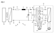
- a circuit arrangement 10 is shown, in which a feed device 12 rectifies an AC voltage of a supply network 14 and feeds the rectified voltage into a DC link 16 on which electric motors 18, 20 are operated.
- the circuit arrangement 10 may be, for example, a production plant or a process plant, or an electrical installation of a crane.
- the electric motors 18, 20 may be components of one and the same production machine 22.
- the electric motors 18, 20 are operated via inverters 24, 26.
- the inverters 24, 26 receive electrical energy from the intermediate circuit 16, to which they are connected via DC voltage connections 28, 30.
- the electrical energy is received by the feed device 12 from the supply network 14.
- the feed device 12 may be, for example, a bridge rectifier which generates the rectified intermediate circuit voltage between lines 36, 39 of the intermediate circuit 16 from alternating voltages of a plurality of phase conductors 32 of the supply network 14 at a DC voltage output 34.
- the lines 36, 38 are relatively long, so that their line inductance L1 in relation to their line resistance R1 represents a large impedance.
- a capacitor C1 may be provided for buffering the intermediate circuit voltage.
- the capacitors C1 in relation to the length of the lines 36, 38 arranged very close to the electric motors 18, 20. If the electric motors 18, 20 are now located relatively far away from the feed unit 12, a vibratory electrical system, namely a blocking circuit, arises via the lines 36, 38 with the no longer negligible line inductance L1 and the capacitor C1, which leads to stability problems on the electric motors 18, 20 can lead. This is below based on FIG. 1 and FIG. 2 explained.
- the input impedance Z1 has a resonance peak as viewed from the electric motor 18.
- the absolute amount M of the input impedance Z1 may be, for example, one kiloohm (1 k ⁇ ).
- the input impedance Z1 is a limiting factor here for the electrical power that can be transmitted from the feed device 12 to the electric motors 18, 20 if the electrical behavior of the electric motors 18, 20 corresponds to a negative impedance, because, for example, the inverters 24, 26 of the electric motors 18, 20 operated according to a power control.
- the intermediate circuit 16 acts between the DC voltage output 34 and the terminal 28 like a blocking circuit with a resonance peak at the resonance frequency f0.
- the electric motor 20 at the terminal 30 observes an input impedance Z2 with respect to the intermediate circuit 16, which has such a resonant peak at the resonance frequency f0.
- the exchangeable by the electric motor 20 with the intermediate circuit 16 power can be increased without having to deviate from a predetermined power setpoint when controlling the operation of the electric motor 20.
- the electric motor 20 can thus always be operated independently of the resonance behavior of the intermediate circuit 16 with the desired power setpoint.
- a damping device 40 is provided in the intermediate circuit 16 for the electric motor 18.
- the damping device 40 comprises a regulating device 42 for the inverter 24 and a measuring device 44.
- the regulating device 42 may comprise, for example, a microcontroller.
- the control device 42 generates in the known manner switching signals for the switching elements of the inverter 24, which generates a three-phase current in the electric motor 18 for generating a magnetic rotating field.
- the switching signals are generated by the control device 42 in accordance with a vector-oriented control, as is known per se from the prior art.
- a control algorithm is now additionally executed for controlling the d-component of the stator current, which actively damps resonances in the intermediate circuit 16.
- the voltage U1 at the terminal 28 is measured by the measuring device 44 in a conventional manner.
- the measuring device 44 transmits a signal of the measured voltage In this case, it may be provided to first filter the measured time profile with a high-pass filter or a bandpass filter and to transmit only the filtered signal to the control device 42. In the filtered signal then only vibrations of the voltage U1 at certain frequencies can be seen.
- the control device 42 has a frequency-selective controller which determines a desired value for the d-component of the stator current as a function of the received signal.
- the curve of the setpoint indicates an increase in the d-component of the stator current for the frequency of the oscillation with increasing voltage U1 and a reduction in the d-component of the stator current when the voltage U1 decreases.
- the inverter 24 is controlled accordingly by the control device 42, so that with increasing voltage U1 a larger current flows into the electric motor 18 and with decreasing voltage a correspondingly reduced current. Since this is the d-component of the stator current, this fluctuation of the current has no influence on the torque of the electric motor 18. Instead, the electric energy taken in the form of the d-component of the stator current is expressed as loss heat in the resistances Rs of the stator windings of the stator Electric motor 18 implemented.
- a particularly advantageous embodiment of the invention can be achieved if the electric motor 18 is a synchronous motor with a high stator resistance Rs. Typical motors of this type are, for example, slow-speed or slow-moving direct drives. If such electric motors are present in the circuit arrangement 10, the high stator resistance Rs for the damping of the oscillations in the intermediate circuit voltage according to the invention can be used for the required power extraction from the intermediate circuit.
- FIG. 2 is the input impedance Z2 plotted against the frequency f, as it results at the terminal 30 from the perspective of the inverter 26 due to the damping effect of the damping device 40. Due to the active DC link attenuation by means of the damping device 40, the input impedance Z2 in the region of the resonant frequency f0 in relation to the input impedance Z1 lowered by several orders of magnitude, so that the consumer-side performance, as they can relate the electric motor 20 from the intermediate circuit 16, can be significantly increased.
- the inverter 24 itself benefits to a slightly lesser extent from the damping device 40, ie with respect to the connections of the inverter 24 to the lines 36, 38 results due to the influenced by the damping device 40 switching behavior of the inverter 24 also has an input impedance, in which at the Resonance point f0 of the intermediate circuit 16, the input impedance in relation to the input impedance Z1 is smaller.
- the damping device 40 is provided in an electric motor 18, which has a lower nominal power in relation to the electric motor 20, which is to benefit significantly from the damping and also does not have to allow as much positioning accuracy as the electric motor 20.
- the damping device 40 is preferably used in a power take-off, so for the main drive 20 or more main drives a vibration-damped DC power supply of the DC link can be provided without there being a reaction to the mechanism driven by these So without a reaction to the speed or the torque or the thrust force acting on the mechanism.
- a comparable arrangement results in cranes, which have a linear drive for a mechanical vibration damping of the crane body.
- a linear drive is a secondary drive, which can also be used for the electrical damping of the intermediate circuit 16, via which the other crane drives for lifting loads and turning the crane are supplied with electrical energy.
- another electrical machine or another electrical load may be connected to the terminal 30, which receives electrical power from the DC bus or even outputs to this.
- the terminal 30 receives electrical power from the DC bus or even outputs to this.
- other electrical consumers or generators can be operated on the intermediate circuit 16.
- the damping device 40 in the immediate vicinity of the consumer, for which the input impedance Z2 is to be attenuated arranged.
- the active damping device 40 can be connected to the intermediate circuit 16 at a different location.
- the damping device 40 can also be used in an electrical machine in the vicinity of a (in FIG. 1 not shown) branch of the intermediate circuit or be connected in the vicinity of the feed 12.
- a special feature of the damping described so far is that the stability of the intermediate circuit 16 is achieved in that the intermediate circuit 16 only energy can be withdrawn to dampen vibrations in the voltage U1, but not supplied. If, instead of a synchronous motor, an asynchronous machine is operated as an electric motor 18 via the damping device 40, then it is also possible to buffer energy in the main field of the asynchronous machine (d-component of the magnetic rotating field) and to restore it to the intermediate circuit 16 for damping oscillations in the voltage U1 leave.
- the inventive method for damping the vibration in the DC link voltage can also be realized by means of an electric generator, in which then also the d-component of its stator current is controlled in the manner described.
- the overall load on the components in the intermediate circuit decreases, such as that of the intermediate circuit capacitor C1, since the alternating currents exchanged between the lines 36, 38 of the intermediate circuit and the components are also smaller due to the damping of the oscillations in the intermediate circuit voltage Have amplitudes and thereby a heating of the components is reduced.
Landscapes
- Engineering & Computer Science (AREA)
- Power Engineering (AREA)
- Control Of Ac Motors In General (AREA)
Priority Applications (1)
| Application Number | Priority Date | Filing Date | Title |
|---|---|---|---|
| EP12164596.4A EP2654199B1 (fr) | 2012-04-18 | 2012-04-18 | Procédé et dispositif de stabilisation d'une tension électrique au moyen d'une régulation orientée champ |
Applications Claiming Priority (1)
| Application Number | Priority Date | Filing Date | Title |
|---|---|---|---|
| EP12164596.4A EP2654199B1 (fr) | 2012-04-18 | 2012-04-18 | Procédé et dispositif de stabilisation d'une tension électrique au moyen d'une régulation orientée champ |
Publications (2)
| Publication Number | Publication Date |
|---|---|
| EP2654199A1 true EP2654199A1 (fr) | 2013-10-23 |
| EP2654199B1 EP2654199B1 (fr) | 2017-08-02 |
Family
ID=46085367
Family Applications (1)
| Application Number | Title | Priority Date | Filing Date |
|---|---|---|---|
| EP12164596.4A Active EP2654199B1 (fr) | 2012-04-18 | 2012-04-18 | Procédé et dispositif de stabilisation d'une tension électrique au moyen d'une régulation orientée champ |
Country Status (1)
| Country | Link |
|---|---|
| EP (1) | EP2654199B1 (fr) |
Cited By (1)
| Publication number | Priority date | Publication date | Assignee | Title |
|---|---|---|---|---|
| US11735990B2 (en) | 2020-11-27 | 2023-08-22 | Schneider Electric Industries Sas | Linear motor system and method for operating |
Citations (3)
| Publication number | Priority date | Publication date | Assignee | Title |
|---|---|---|---|---|
| JP2000278982A (ja) * | 1999-03-24 | 2000-10-06 | Hitachi Ltd | 永久磁石式同期モータの制御方法 |
| US20090256518A1 (en) * | 2006-07-06 | 2009-10-15 | Mitsubishi Electric Corporation | Vector control device of induction motor, vector control method of induction motor, and drive control device of induction motor |
| US20110038192A1 (en) * | 2008-04-18 | 2011-02-17 | Daikin Industries, Ltd. | Converter control method |
-
2012
- 2012-04-18 EP EP12164596.4A patent/EP2654199B1/fr active Active
Patent Citations (3)
| Publication number | Priority date | Publication date | Assignee | Title |
|---|---|---|---|---|
| JP2000278982A (ja) * | 1999-03-24 | 2000-10-06 | Hitachi Ltd | 永久磁石式同期モータの制御方法 |
| US20090256518A1 (en) * | 2006-07-06 | 2009-10-15 | Mitsubishi Electric Corporation | Vector control device of induction motor, vector control method of induction motor, and drive control device of induction motor |
| US20110038192A1 (en) * | 2008-04-18 | 2011-02-17 | Daikin Industries, Ltd. | Converter control method |
Non-Patent Citations (1)
| Title |
|---|
| HANSEN A D ET AL: "Multi-pole permanent magnet synchronous generator wind turbines' grid support capability in uninterrupted operation during grid faults", IET RENEWABLE POWER GENERATION,, vol. 3, no. 3, 8 September 2009 (2009-09-08), pages 333 - 348, XP006033760, ISSN: 1752-1424, DOI: 10.1049/IET-RPG:20080055 * |
Cited By (1)
| Publication number | Priority date | Publication date | Assignee | Title |
|---|---|---|---|---|
| US11735990B2 (en) | 2020-11-27 | 2023-08-22 | Schneider Electric Industries Sas | Linear motor system and method for operating |
Also Published As
| Publication number | Publication date |
|---|---|
| EP2654199B1 (fr) | 2017-08-02 |
Similar Documents
| Publication | Publication Date | Title |
|---|---|---|
| EP2258945B1 (fr) | Procédé d'exploitation d'une installation d'énergie éolienne | |
| EP3120451B1 (fr) | Alimentation électrique pour une charge non linéaire dotée de convertisseurs matriciels à plusieurs niveaux | |
| DE102017006819A1 (de) | System und Verfahren zum Betreiben eines Systems | |
| EP2979352B1 (fr) | Dispositif, en particulier machine ou installation, et procédé permettant de faire fonctionner un dispositif | |
| EP3763026B1 (fr) | Procédé d'opération d'un système d'entrainement électrique avec accumulateur d'énergie et dispositif pour réaliser ce procédé | |
| EP2619900B1 (fr) | Procédé de régulation optimisée en termes de pertes (dans le cuivre) pour un moteur asynchrone au moyen d'un convertisseur | |
| DE102010025647A1 (de) | Vorrichtung und Verfahren zur intelligenten Netzleistungsregulierung durch kapazitive Energiespeicherung | |
| EP2654199B1 (fr) | Procédé et dispositif de stabilisation d'une tension électrique au moyen d'une régulation orientée champ | |
| EP2654160B1 (fr) | Procédé et circuit destinés à la stabilisation d'une tension électrique dans un circuit intermédiaire | |
| EP3297115A1 (fr) | Système comprenant un dispositif d'accumulation d'énergie et un convertisseur d'énergie destiné à recevoir de l'énergie électrique provenant d'un réseau électrique et fournir l'énergie électrique au réseau électrique | |
| DE102012012619A1 (de) | Vorrichtung und Verfahren zur elektrischen Energieversorgung einer industriellen Anlage | |
| EP4026216B1 (fr) | Procédé de fonctionnement d'un système, et système | |
| EP3759783A1 (fr) | Dispositif de connexion d'un réseau partiel à un réseau à tension alternative et procédé de commande d'une sortie électrique | |
| DE102007027221A1 (de) | Frequenzumrichter sowie Verfahren zum Betreiben eines Elektromotors mit einem solchen Frequenzumrichter | |
| EP2911259B1 (fr) | Utilisation d'un entraînement à régime régulé pour la stabilisation du réseau | |
| DE102011086988B3 (de) | Verfahren zum Betrieb einer Windturbine | |
| DE102005036802C5 (de) | Verfahren und Vorrichtung zur Steigerung der Effizienz eines Elektromotors | |
| DE102007042246A1 (de) | Verfahren und Regeleinheit zur Kurzschlußstromreduktion bei einer doppeltgespeisten Asynchronmaschine | |
| EP1493218B1 (fr) | Systeme d'arret d'urgence pour consommateurs alimentes par induction | |
| EP4022733A1 (fr) | Installation et procédé pour stabiliser un réseau électrique | |
| EP2975747B1 (fr) | Amélioration d'une tension d'une liaison d'alimentation en courant | |
| DE102015009073B4 (de) | Anordnung zur induktiven Übertragung elektrischer Energie von einem stationär angeordneten Primärleiter an eine relativ dazu bewegbare Vorrichtung und Verfahren zum Betreiben der Anordnung | |
| WO2024188530A1 (fr) | Procédé et unité de commande pour réduire des flux de puissance harmoniques et sous-réseau comprenant une unité de commande | |
| AT514175B1 (de) | Energieversorgungsvorrichtung für eine Spritzgießmaschine | |
| AT117279B (de) | Regelanordnung für elektrische Maschinen. |
Legal Events
| Date | Code | Title | Description |
|---|---|---|---|
| PUAI | Public reference made under article 153(3) epc to a published international application that has entered the european phase |
Free format text: ORIGINAL CODE: 0009012 |
|
| AK | Designated contracting states |
Kind code of ref document: A1 Designated state(s): AL AT BE BG CH CY CZ DE DK EE ES FI FR GB GR HR HU IE IS IT LI LT LU LV MC MK MT NL NO PL PT RO RS SE SI SK SM TR |
|
| AX | Request for extension of the european patent |
Extension state: BA ME |
|
| 17P | Request for examination filed |
Effective date: 20140417 |
|
| RBV | Designated contracting states (corrected) |
Designated state(s): AL AT BE BG CH CY CZ DE DK EE ES FI FR GB GR HR HU IE IS IT LI LT LU LV MC MK MT NL NO PL PT RO RS SE SI SK SM TR |
|
| GRAP | Despatch of communication of intention to grant a patent |
Free format text: ORIGINAL CODE: EPIDOSNIGR1 |
|
| RIC1 | Information provided on ipc code assigned before grant |
Ipc: H02P 21/00 20160101AFI20170202BHEP |
|
| INTG | Intention to grant announced |
Effective date: 20170302 |
|
| GRAS | Grant fee paid |
Free format text: ORIGINAL CODE: EPIDOSNIGR3 |
|
| GRAA | (expected) grant |
Free format text: ORIGINAL CODE: 0009210 |
|
| AK | Designated contracting states |
Kind code of ref document: B1 Designated state(s): AL AT BE BG CH CY CZ DE DK EE ES FI FR GB GR HR HU IE IS IT LI LT LU LV MC MK MT NL NO PL PT RO RS SE SI SK SM TR |
|
| REG | Reference to a national code |
Ref country code: CH Ref legal event code: EP Ref country code: AT Ref legal event code: REF Ref document number: 915484 Country of ref document: AT Kind code of ref document: T Effective date: 20170815 |
|
| REG | Reference to a national code |
Ref country code: IE Ref legal event code: FG4D Free format text: LANGUAGE OF EP DOCUMENT: GERMAN |
|
| RAP2 | Party data changed (patent owner data changed or rights of a patent transferred) |
Owner name: SIEMENS AKTIENGESELLSCHAFT |
|
| REG | Reference to a national code |
Ref country code: CH Ref legal event code: NV Representative=s name: SIEMENS SCHWEIZ AG, CH |
|
| REG | Reference to a national code |
Ref country code: DE Ref legal event code: R096 Ref document number: 502012010888 Country of ref document: DE |
|
| REG | Reference to a national code |
Ref country code: NL Ref legal event code: MP Effective date: 20170802 |
|
| REG | Reference to a national code |
Ref country code: LT Ref legal event code: MG4D |
|
| PG25 | Lapsed in a contracting state [announced via postgrant information from national office to epo] |
Ref country code: NL Free format text: LAPSE BECAUSE OF FAILURE TO SUBMIT A TRANSLATION OF THE DESCRIPTION OR TO PAY THE FEE WITHIN THE PRESCRIBED TIME-LIMIT Effective date: 20170802 Ref country code: HR Free format text: LAPSE BECAUSE OF FAILURE TO SUBMIT A TRANSLATION OF THE DESCRIPTION OR TO PAY THE FEE WITHIN THE PRESCRIBED TIME-LIMIT Effective date: 20170802 Ref country code: FI Free format text: LAPSE BECAUSE OF FAILURE TO SUBMIT A TRANSLATION OF THE DESCRIPTION OR TO PAY THE FEE WITHIN THE PRESCRIBED TIME-LIMIT Effective date: 20170802 Ref country code: SE Free format text: LAPSE BECAUSE OF FAILURE TO SUBMIT A TRANSLATION OF THE DESCRIPTION OR TO PAY THE FEE WITHIN THE PRESCRIBED TIME-LIMIT Effective date: 20170802 Ref country code: LT Free format text: LAPSE BECAUSE OF FAILURE TO SUBMIT A TRANSLATION OF THE DESCRIPTION OR TO PAY THE FEE WITHIN THE PRESCRIBED TIME-LIMIT Effective date: 20170802 Ref country code: NO Free format text: LAPSE BECAUSE OF FAILURE TO SUBMIT A TRANSLATION OF THE DESCRIPTION OR TO PAY THE FEE WITHIN THE PRESCRIBED TIME-LIMIT Effective date: 20171102 |
|
| PG25 | Lapsed in a contracting state [announced via postgrant information from national office to epo] |
Ref country code: PL Free format text: LAPSE BECAUSE OF FAILURE TO SUBMIT A TRANSLATION OF THE DESCRIPTION OR TO PAY THE FEE WITHIN THE PRESCRIBED TIME-LIMIT Effective date: 20170802 Ref country code: BG Free format text: LAPSE BECAUSE OF FAILURE TO SUBMIT A TRANSLATION OF THE DESCRIPTION OR TO PAY THE FEE WITHIN THE PRESCRIBED TIME-LIMIT Effective date: 20171102 Ref country code: GR Free format text: LAPSE BECAUSE OF FAILURE TO SUBMIT A TRANSLATION OF THE DESCRIPTION OR TO PAY THE FEE WITHIN THE PRESCRIBED TIME-LIMIT Effective date: 20171103 Ref country code: RS Free format text: LAPSE BECAUSE OF FAILURE TO SUBMIT A TRANSLATION OF THE DESCRIPTION OR TO PAY THE FEE WITHIN THE PRESCRIBED TIME-LIMIT Effective date: 20170802 Ref country code: ES Free format text: LAPSE BECAUSE OF FAILURE TO SUBMIT A TRANSLATION OF THE DESCRIPTION OR TO PAY THE FEE WITHIN THE PRESCRIBED TIME-LIMIT Effective date: 20170802 Ref country code: LV Free format text: LAPSE BECAUSE OF FAILURE TO SUBMIT A TRANSLATION OF THE DESCRIPTION OR TO PAY THE FEE WITHIN THE PRESCRIBED TIME-LIMIT Effective date: 20170802 Ref country code: IS Free format text: LAPSE BECAUSE OF FAILURE TO SUBMIT A TRANSLATION OF THE DESCRIPTION OR TO PAY THE FEE WITHIN THE PRESCRIBED TIME-LIMIT Effective date: 20171202 |
|
| REG | Reference to a national code |
Ref country code: FR Ref legal event code: PLFP Year of fee payment: 7 |
|
| PG25 | Lapsed in a contracting state [announced via postgrant information from national office to epo] |
Ref country code: CZ Free format text: LAPSE BECAUSE OF FAILURE TO SUBMIT A TRANSLATION OF THE DESCRIPTION OR TO PAY THE FEE WITHIN THE PRESCRIBED TIME-LIMIT Effective date: 20170802 Ref country code: DK Free format text: LAPSE BECAUSE OF FAILURE TO SUBMIT A TRANSLATION OF THE DESCRIPTION OR TO PAY THE FEE WITHIN THE PRESCRIBED TIME-LIMIT Effective date: 20170802 Ref country code: RO Free format text: LAPSE BECAUSE OF FAILURE TO SUBMIT A TRANSLATION OF THE DESCRIPTION OR TO PAY THE FEE WITHIN THE PRESCRIBED TIME-LIMIT Effective date: 20170802 |
|
| REG | Reference to a national code |
Ref country code: DE Ref legal event code: R097 Ref document number: 502012010888 Country of ref document: DE |
|
| PG25 | Lapsed in a contracting state [announced via postgrant information from national office to epo] |
Ref country code: SK Free format text: LAPSE BECAUSE OF FAILURE TO SUBMIT A TRANSLATION OF THE DESCRIPTION OR TO PAY THE FEE WITHIN THE PRESCRIBED TIME-LIMIT Effective date: 20170802 Ref country code: EE Free format text: LAPSE BECAUSE OF FAILURE TO SUBMIT A TRANSLATION OF THE DESCRIPTION OR TO PAY THE FEE WITHIN THE PRESCRIBED TIME-LIMIT Effective date: 20170802 Ref country code: SM Free format text: LAPSE BECAUSE OF FAILURE TO SUBMIT A TRANSLATION OF THE DESCRIPTION OR TO PAY THE FEE WITHIN THE PRESCRIBED TIME-LIMIT Effective date: 20170802 |
|
| PLBE | No opposition filed within time limit |
Free format text: ORIGINAL CODE: 0009261 |
|
| STAA | Information on the status of an ep patent application or granted ep patent |
Free format text: STATUS: NO OPPOSITION FILED WITHIN TIME LIMIT |
|
| 26N | No opposition filed |
Effective date: 20180503 |
|
| PG25 | Lapsed in a contracting state [announced via postgrant information from national office to epo] |
Ref country code: SI Free format text: LAPSE BECAUSE OF FAILURE TO SUBMIT A TRANSLATION OF THE DESCRIPTION OR TO PAY THE FEE WITHIN THE PRESCRIBED TIME-LIMIT Effective date: 20170802 |
|
| PG25 | Lapsed in a contracting state [announced via postgrant information from national office to epo] |
Ref country code: MT Free format text: LAPSE BECAUSE OF FAILURE TO SUBMIT A TRANSLATION OF THE DESCRIPTION OR TO PAY THE FEE WITHIN THE PRESCRIBED TIME-LIMIT Effective date: 20170802 |
|
| PG25 | Lapsed in a contracting state [announced via postgrant information from national office to epo] |
Ref country code: MC Free format text: LAPSE BECAUSE OF FAILURE TO SUBMIT A TRANSLATION OF THE DESCRIPTION OR TO PAY THE FEE WITHIN THE PRESCRIBED TIME-LIMIT Effective date: 20170802 |
|
| REG | Reference to a national code |
Ref country code: BE Ref legal event code: MM Effective date: 20180430 |
|
| GBPC | Gb: european patent ceased through non-payment of renewal fee |
Effective date: 20180418 |
|
| REG | Reference to a national code |
Ref country code: IE Ref legal event code: MM4A |
|
| PG25 | Lapsed in a contracting state [announced via postgrant information from national office to epo] |
Ref country code: LU Free format text: LAPSE BECAUSE OF NON-PAYMENT OF DUE FEES Effective date: 20180418 |
|
| PG25 | Lapsed in a contracting state [announced via postgrant information from national office to epo] |
Ref country code: GB Free format text: LAPSE BECAUSE OF NON-PAYMENT OF DUE FEES Effective date: 20180418 Ref country code: BE Free format text: LAPSE BECAUSE OF NON-PAYMENT OF DUE FEES Effective date: 20180430 |
|
| PG25 | Lapsed in a contracting state [announced via postgrant information from national office to epo] |
Ref country code: IE Free format text: LAPSE BECAUSE OF NON-PAYMENT OF DUE FEES Effective date: 20180418 |
|
| PG25 | Lapsed in a contracting state [announced via postgrant information from national office to epo] |
Ref country code: TR Free format text: LAPSE BECAUSE OF FAILURE TO SUBMIT A TRANSLATION OF THE DESCRIPTION OR TO PAY THE FEE WITHIN THE PRESCRIBED TIME-LIMIT Effective date: 20170802 |
|
| PG25 | Lapsed in a contracting state [announced via postgrant information from national office to epo] |
Ref country code: PT Free format text: LAPSE BECAUSE OF FAILURE TO SUBMIT A TRANSLATION OF THE DESCRIPTION OR TO PAY THE FEE WITHIN THE PRESCRIBED TIME-LIMIT Effective date: 20170802 Ref country code: HU Free format text: LAPSE BECAUSE OF FAILURE TO SUBMIT A TRANSLATION OF THE DESCRIPTION OR TO PAY THE FEE WITHIN THE PRESCRIBED TIME-LIMIT; INVALID AB INITIO Effective date: 20120418 |
|
| PG25 | Lapsed in a contracting state [announced via postgrant information from national office to epo] |
Ref country code: MK Free format text: LAPSE BECAUSE OF NON-PAYMENT OF DUE FEES Effective date: 20170802 Ref country code: CY Free format text: LAPSE BECAUSE OF FAILURE TO SUBMIT A TRANSLATION OF THE DESCRIPTION OR TO PAY THE FEE WITHIN THE PRESCRIBED TIME-LIMIT Effective date: 20170802 |
|
| PG25 | Lapsed in a contracting state [announced via postgrant information from national office to epo] |
Ref country code: AL Free format text: LAPSE BECAUSE OF FAILURE TO SUBMIT A TRANSLATION OF THE DESCRIPTION OR TO PAY THE FEE WITHIN THE PRESCRIBED TIME-LIMIT Effective date: 20170802 |
|
| PGFP | Annual fee paid to national office [announced via postgrant information from national office to epo] |
Ref country code: FR Payment date: 20210419 Year of fee payment: 10 |
|
| PGFP | Annual fee paid to national office [announced via postgrant information from national office to epo] |
Ref country code: AT Payment date: 20210305 Year of fee payment: 10 |
|
| PGFP | Annual fee paid to national office [announced via postgrant information from national office to epo] |
Ref country code: CH Payment date: 20210705 Year of fee payment: 10 |
|
| REG | Reference to a national code |
Ref country code: CH Ref legal event code: PL |
|
| REG | Reference to a national code |
Ref country code: AT Ref legal event code: MM01 Ref document number: 915484 Country of ref document: AT Kind code of ref document: T Effective date: 20220418 |
|
| PG25 | Lapsed in a contracting state [announced via postgrant information from national office to epo] |
Ref country code: LI Free format text: LAPSE BECAUSE OF NON-PAYMENT OF DUE FEES Effective date: 20220430 Ref country code: FR Free format text: LAPSE BECAUSE OF NON-PAYMENT OF DUE FEES Effective date: 20220430 Ref country code: CH Free format text: LAPSE BECAUSE OF NON-PAYMENT OF DUE FEES Effective date: 20220430 Ref country code: AT Free format text: LAPSE BECAUSE OF NON-PAYMENT OF DUE FEES Effective date: 20220418 |
|
| PGFP | Annual fee paid to national office [announced via postgrant information from national office to epo] |
Ref country code: DE Payment date: 20250620 Year of fee payment: 14 |
|
| PGFP | Annual fee paid to national office [announced via postgrant information from national office to epo] |
Ref country code: IT Payment date: 20250417 Year of fee payment: 14 |