EP4000656A2 - Dispositif et procédé de réduction de la charge en substances nocives dans un gaz - Google Patents
Dispositif et procédé de réduction de la charge en substances nocives dans un gaz Download PDFInfo
- Publication number
- EP4000656A2 EP4000656A2 EP21206366.3A EP21206366A EP4000656A2 EP 4000656 A2 EP4000656 A2 EP 4000656A2 EP 21206366 A EP21206366 A EP 21206366A EP 4000656 A2 EP4000656 A2 EP 4000656A2
- Authority
- EP
- European Patent Office
- Prior art keywords
- gas
- capillary material
- disinfection
- flow
- disinfection space
- Prior art date
- Legal status (The legal status is an assumption and is not a legal conclusion. Google has not performed a legal analysis and makes no representation as to the accuracy of the status listed.)
- Granted
Links
Images

Classifications
-
- B—PERFORMING OPERATIONS; TRANSPORTING
- B01—PHYSICAL OR CHEMICAL PROCESSES OR APPARATUS IN GENERAL
- B01D—SEPARATION
- B01D53/00—Separation of gases or vapours; Recovering vapours of volatile solvents from gases; Chemical or biological purification of waste gases, e.g. engine exhaust gases, smoke, fumes, flue gases, aerosols
- B01D53/34—Chemical or biological purification of waste gases
- B01D53/46—Removing components of defined structure
- B01D53/72—Organic compounds not provided for in groups B01D53/48 - B01D53/70, e.g. hydrocarbons
-
- B—PERFORMING OPERATIONS; TRANSPORTING
- B01—PHYSICAL OR CHEMICAL PROCESSES OR APPARATUS IN GENERAL
- B01D—SEPARATION
- B01D47/00—Separating dispersed particles from gases, air or vapours by liquid as separating agent
- B01D47/02—Separating dispersed particles from gases, air or vapours by liquid as separating agent by passing the gas or air or vapour over or through a liquid bath
-
- B—PERFORMING OPERATIONS; TRANSPORTING
- B01—PHYSICAL OR CHEMICAL PROCESSES OR APPARATUS IN GENERAL
- B01D—SEPARATION
- B01D53/00—Separation of gases or vapours; Recovering vapours of volatile solvents from gases; Chemical or biological purification of waste gases, e.g. engine exhaust gases, smoke, fumes, flue gases, aerosols
- B01D53/007—Separation of gases or vapours; Recovering vapours of volatile solvents from gases; Chemical or biological purification of waste gases, e.g. engine exhaust gases, smoke, fumes, flue gases, aerosols by irradiation
-
- A—HUMAN NECESSITIES
- A61—MEDICAL OR VETERINARY SCIENCE; HYGIENE
- A61L—METHODS OR APPARATUS FOR STERILISING MATERIALS OR OBJECTS IN GENERAL; DISINFECTION, STERILISATION OR DEODORISATION OF AIR; CHEMICAL ASPECTS OF BANDAGES, DRESSINGS, ABSORBENT PADS OR SURGICAL ARTICLES; MATERIALS FOR BANDAGES, DRESSINGS, ABSORBENT PADS OR SURGICAL ARTICLES
- A61L2209/00—Aspects relating to disinfection, sterilisation or deodorisation of air
- A61L2209/20—Method-related aspects
- A61L2209/21—Use of chemical compounds for treating air or the like
- A61L2209/211—Use of hydrogen peroxide, liquid and vaporous
-
- A—HUMAN NECESSITIES
- A61—MEDICAL OR VETERINARY SCIENCE; HYGIENE
- A61L—METHODS OR APPARATUS FOR STERILISING MATERIALS OR OBJECTS IN GENERAL; DISINFECTION, STERILISATION OR DEODORISATION OF AIR; CHEMICAL ASPECTS OF BANDAGES, DRESSINGS, ABSORBENT PADS OR SURGICAL ARTICLES; MATERIALS FOR BANDAGES, DRESSINGS, ABSORBENT PADS OR SURGICAL ARTICLES
- A61L9/00—Disinfection, sterilisation or deodorisation of air
- A61L9/16—Disinfection, sterilisation or deodorisation of air using physical phenomena
- A61L9/18—Radiation
- A61L9/20—Ultraviolet radiation
-
- B—PERFORMING OPERATIONS; TRANSPORTING
- B01—PHYSICAL OR CHEMICAL PROCESSES OR APPARATUS IN GENERAL
- B01D—SEPARATION
- B01D2251/00—Reactants
- B01D2251/10—Oxidants
- B01D2251/106—Peroxides
-
- B—PERFORMING OPERATIONS; TRANSPORTING
- B01—PHYSICAL OR CHEMICAL PROCESSES OR APPARATUS IN GENERAL
- B01D—SEPARATION
- B01D2253/00—Adsorbents used in seperation treatment of gases and vapours
- B01D2253/10—Inorganic adsorbents
- B01D2253/102—Carbon
-
- B—PERFORMING OPERATIONS; TRANSPORTING
- B01—PHYSICAL OR CHEMICAL PROCESSES OR APPARATUS IN GENERAL
- B01D—SEPARATION
- B01D2257/00—Components to be removed
- B01D2257/91—Bacteria; Microorganisms
-
- B—PERFORMING OPERATIONS; TRANSPORTING
- B01—PHYSICAL OR CHEMICAL PROCESSES OR APPARATUS IN GENERAL
- B01D—SEPARATION
- B01D2258/00—Sources of waste gases
- B01D2258/06—Polluted air
-
- B—PERFORMING OPERATIONS; TRANSPORTING
- B01—PHYSICAL OR CHEMICAL PROCESSES OR APPARATUS IN GENERAL
- B01D—SEPARATION
- B01D2259/00—Type of treatment
- B01D2259/10—Gas phase, e.g. by using aerosols
-
- B—PERFORMING OPERATIONS; TRANSPORTING
- B01—PHYSICAL OR CHEMICAL PROCESSES OR APPARATUS IN GENERAL
- B01D—SEPARATION
- B01D2259/00—Type of treatment
- B01D2259/12—Methods and means for introducing reactants
- B01D2259/124—Liquid reactants
-
- B—PERFORMING OPERATIONS; TRANSPORTING
- B01—PHYSICAL OR CHEMICAL PROCESSES OR APPARATUS IN GENERAL
- B01D—SEPARATION
- B01D2259/00—Type of treatment
- B01D2259/45—Gas separation or purification devices adapted for specific applications
- B01D2259/4508—Gas separation or purification devices adapted for specific applications for cleaning air in buildings
-
- B—PERFORMING OPERATIONS; TRANSPORTING
- B01—PHYSICAL OR CHEMICAL PROCESSES OR APPARATUS IN GENERAL
- B01D—SEPARATION
- B01D2259/00—Type of treatment
- B01D2259/80—Employing electric, magnetic, electromagnetic or wave energy, or particle radiation
- B01D2259/804—UV light
-
- B—PERFORMING OPERATIONS; TRANSPORTING
- B01—PHYSICAL OR CHEMICAL PROCESSES OR APPARATUS IN GENERAL
- B01D—SEPARATION
- B01D46/00—Filters or filtering processes specially modified for separating dispersed particles from gases or vapours
- B01D46/0027—Filters or filtering processes specially modified for separating dispersed particles from gases or vapours with additional separating or treating functions
- B01D46/0036—Filters or filtering processes specially modified for separating dispersed particles from gases or vapours with additional separating or treating functions by adsorption or absorption
-
- B—PERFORMING OPERATIONS; TRANSPORTING
- B01—PHYSICAL OR CHEMICAL PROCESSES OR APPARATUS IN GENERAL
- B01D—SEPARATION
- B01D46/00—Filters or filtering processes specially modified for separating dispersed particles from gases or vapours
- B01D46/10—Particle separators, e.g. dust precipitators, using filter plates, sheets or pads having plane surfaces
-
- B—PERFORMING OPERATIONS; TRANSPORTING
- B01—PHYSICAL OR CHEMICAL PROCESSES OR APPARATUS IN GENERAL
- B01D—SEPARATION
- B01D50/00—Combinations of methods or devices for separating particles from gases or vapours
- B01D50/60—Combinations of devices covered by groups B01D46/00 and B01D47/00
Definitions
- the invention relates to a device for reducing a pollutant load in a gas, having a gas inlet and a gas outlet, as well as a disinfection space arranged between them, according to the preamble of claim 1.
- the invention also relates to a system for influencing a gas flow, having a base unit with at least one turbomachine and a device for reducing pollution in the gas, which is connected to the base unit as an extension of the base unit.
- the invention also relates to a method for reducing a pollutant load in a gas, according to the preamble of claim 15.
- the well-known air cleaners usually use a combination of different mechanical filters (e.g. HEPA filters) and activated carbon filters as well as optional additional UV-C radiation.
- WO 2015/059336 A1 In order to improve the filter effect and also to increase the air throughput, devices for air purification are also known, in which the purification takes place through the emission of hydroxyl radicals.
- a device is, for example, in the generic WO 2015/059336 A1 described.
- the device of WO 2015/059336 A1 features a cartridge containing a liquid reactant capable of generating hydroxyl radicals by reaction with ultraviolet radiation.
- a wick extends from the cartridge and protrudes into the airflow. The wick is thus swept by the air flow, as a result of which the reactant is partially released into the air.
- Hydroxyl radicals are then generated in the aerosol by means of a UV beam generator.
- the hydroxyl radicals are able to break down organic impurities and thus primarily the pollutants contained in the air. This type of disinfection is quick and highly effective.
- the object of the present invention is to provide a device by means of which a pollutant load in a gas can be reduced reliably and with a preferably high gas throughput, in particular with technically simple means.
- the invention is also based on the object of providing a system for influencing a gas flow, in which a base unit, which has a turbomachine, can be expanded with an advantageous device for reducing pollution in a gas.
- the present invention is also based on the object of providing a method with which a pollutant load in a gas can be reduced reliably and with a preferably high gas throughput, in particular with technically simple means.
- the object is achieved for the device with the features listed in claim 1.
- the object is solved by claim 14.
- the object is achieved by the features of claim 15.
- a device for reducing pollution in a gas (or gas mixture) having a gas inlet and a gas outlet, and a disinfection space arranged between them, through which a gas stream running from the gas inlet to the gas outlet can flow.
- pollutants can be pathogens such as viruses, bacteria or spores, pathogens or other pollutants such as pollen, odours, dust and microparticles, volatile organic compounds and/or scales.
- pathogens such as viruses, bacteria or spores, pathogens or other pollutants such as pollen, odours, dust and microparticles, volatile organic compounds and/or scales.
- the device according to the invention is particularly suitable for reducing organic pollution.
- the gas or gas mixture to be freed from the pollutants can in particular be air, preferably room air.
- the reduction in the pollutant load preferably takes place essentially within the disinfection space, particularly preferably exclusively within the disinfection space.
- an aerosol generation arrangement having a capillary material is arranged within the disinfection space so that the gas stream can flow through it.
- An aerosol generation arrangement is to be understood in particular as an arrangement which causes the oxidizing agent to be mixed with the gas to be freed from the pollutants.
- the aerosol generating arrangement generates an aerosol from the oxidizing agent and the gas.
- the aerosol generating arrangement can generate any desired mixture of the gas and liquid, solid and/or gaseous particles of the oxidizing agent. For example, a vapor can also be generated.
- a capillary material is to be understood in particular as a material that causes a capillary effect on a liquid when it comes into contact with it, whereby the liquid is able to rise in the capillary material without external influence or whereby the capillary material is able to soak up the liquid.
- the capillary material is preferably distributed in the aerosol generation arrangement in such a way that it makes the largest possible surface area available to the gas stream flowing past.
- the capillary material is preferably distributed in the aerosol generation arrangement.
- the gas flow can flow through the aerosol generating arrangement, but not through the capillary material itself.
- the capillary material should preferably not function as a wet filter.
- the capillary material is preferably arranged in such a way that the gas stream can flow past it in parallel or along its surface, but does not flow through the surface. In this way, a particularly high volume flow can be possible.
- a gas inlet nozzle extending at least in sections along its longitudinal axis into the disinfection space.
- the gas inlet nozzle can be designed to conduct the gas, starting from the gas inlet, into the disinfection space.
- the flow machine described below can preferably be arranged between the gas inlet and the gas inlet connection piece.
- the capillary material extends into a liquid reservoir in which a liquid oxidizing agent is contained.
- the liquid oxidizing agent can be present in its pure form or as a mixture with another liquid, in particular as a mixture with another oxidizing agent, water, alcohol and/or an additional disinfectant.
- the capillary material extends into the liquid reservoir, it is in direct connection with the liquid oxidizing agent, preferably statically or immovably, whereby the capillary material automatically soaks up the oxidizing agent due to the capillary effect, optionally also against the force of gravity.
- the liquid oxidizing agent can be distributed over a large area within the disinfection room without the need for special technical means (such as actuators, pumps, nozzles, etc.).
- the gas flowing past the capillary material wetted with the oxidizing agent causes the liquid oxidizing agent to form a large amount of aerosol.
- the oxidizing agent can be distributed extensively within the gas using technically simple means, have a disinfecting effect in the gas and thus reduce its pollutant load. It has been shown that this reaction takes place extremely quickly and reliably, which is why a particularly high gas throughput can also be achieved by means of the device according to the invention.
- the capillary material is preferably arranged/attached statically or immovably within the disinfection space.
- the capillary material is wetted or soaked with the liquid oxidizing agent through a hose or line system.
- the liquid oxidant can be transported either passively (particularly by gravity) or by a controlled or uncontrolled pumping unit.
- the reservoir can advantageously serve as a collecting container for dripping liquid, which is then taken up again by the capillary action of the capillary material.
- At least one inner wall of the disinfection chamber is at least partially lined with the capillary material of the aerosol generation arrangement. All inner walls of the disinfection space are preferably at least partially lined with the capillary material.
- any recesses in the inner walls for the gas inlet and gas outlet are preferably recessed and are therefore not covered by the capillary material.
- the capillary material is preferably bonded to the at least one inner wall, preferably glued.
- the capillary material can also be connected to the at least one inner wall of the disinfection space in a non-positive or positive manner.
- the capillary material does not completely cover the at least one inner wall of the disinfection space and, for example, only extends over a partial area of the longitudinal extent of the disinfection space.
- the capillary material can be distributed as desired within the aerosol generation arrangement, preferably with the aim of presenting the largest possible surface area to the gas stream flowing past.
- the capillary material is preferably arranged within the aerosol generation arrangement in such a way that the gas stream is able to flow past the surface of the capillary material that is wetted with the liquid oxidizing agent, at least essentially in parallel.
- Means for swirling the gas in the disinfection space can be provided, in particular in the area of the gas inlet, for example also in the area of the gas inlet nozzle.
- one air baffle or several air baffles and/or air baffles can be provided. The residence time and exposure time inside the disinfection room can be further improved in this way.
- the capillary material can be distributed between the inner walls of the disinfection chamber as an alternative or in addition to the lining of the at least one inner wall, for example in the form of a plate, zigzag, spiral, in the form of a hollow body (for example a concentrically open cylinder or a concentrically open cuboid) or on other way.
- a hollow body for example a concentrically open cylinder or a concentrically open cuboid
- the aerosol generating arrangement has at least one elongated body formed from the capillary material (a preferably narrow body with a greater length than width/thickness), which extends through the disinfection space.
- the elongate body can be, for example, a cylinder-like body (solid or hollow cylinder), strips or plates of the capillary material and/or threads or braids made of the capillary material.
- the longitudinal axis of the elongate body is arranged parallel to the longitudinal axis of the disinfection space.
- a plurality of elongate bodies are preferably provided, which are distributed within the disinfection space.
- the elongate bodies may each have a first (lower) end and a second (upper) end.
- the elongate bodies preferably project with their first end into the liquid reservoir and extend through the disinfection space, starting from the first end to the second end.
- the elongated bodies can, for example, in the area of the second end be fixed in the disinfection room, in particular via a common mounting plate.
- the capillary material is a porous, inorganic material.
- the capillary material is a fiberglass fabric.
- any capillary material can be provided, even an organic capillary material (e.g. cotton).
- an organic material is not preferred since an inorganic material can generally have a relatively long to unlimited shelf life under the influence of the oxidizing agent.
- the capillary material can be a ceramic, a textile, in particular a woven fabric, knitted fabric, knitted fabric or scrim, a fleece or paper. A combination of several materials can optionally also be provided.
- the capillary material is particularly preferably a glass fiber mesh or a glass fiber mat.
- At least one radiation source for generating ionizing radiation is arranged inside the disinfection room.
- Precisely one radiation source is preferably provided, which is arranged in particular as centrally as possible within the disinfection room.
- ionizing radiation can be understood to mean, in particular, radiation with a wavelength range of 400 nm and less, preferably 250 nm and less.
- a UV-C radiation source is preferably provided for generating UV-C radiation.
- the wavelength of the ultraviolet radiation can be 100 nm to 300 nm, for example. Radiation with wavelengths deviating from this can, however, also be provided, in particular radiation with even shorter wavelengths.
- UV-C radiation with a wavelength of 240 nm to 260 nm is preferably provided, in particular 254 nm to 260 nm, particularly preferably 258 nm, since this wavelength range has a particularly strong germicidal effect.
- the disinfecting effect ionizing radiation, in particular UV-C radiation, is known, which is why no further explanations are given here.
- a combination of the oxidizing agent distributed as an aerosol by means of the capillary material and ionizing radiation can considerably enhance the disinfecting effect of the device, in particular through the formation of free radicals from the liquid oxidizing agent by the ionizing radiation.
- Ultraviolet radiation very particularly short-wave ultraviolet radiation, in particular UV-C radiation (100 nm to 280 nm), has proven to be particularly suitable radiation for this combination.
- Ionizing radiation is preferably used in a wavelength range in which no ozone is generated, or only to a negligible extent.
- the UV-C radiation source can have, for example, a mercury vapor lamp, a quartz lamp, a UV light-emitting diode or a diode laser, a UV cold-cathode tube or another artificial UV-C source.
- UV-C light-emitting diodes can preferably be distributed in a row arrangement, in particular in a band arrangement, in order to provide UV-C radiation over the greatest possible longitudinal extent.
- the UV-C radiation source can have an adjustable intensity and/or wavelength and can therefore be adapted as required.
- the intensity and/or wavelength can, for example, be adjustable manually by a user of the device and/or automatically by a control device of the device.
- the adjustment of intensity and/or wavelength can be based on different cleaning programs for different types of pollutants and/or different power levels, which can be adjusted discretely or continuously (manually or automatically).
- the optimum wavelength of ionizing radiation, especially UV-C radiation, and the deadly intensity can vary for different types of pollution (e.g. viruses, bacteria, spores, etc.).
- Corresponding wavelengths and intensities for the photolysis of various pollutants are sufficiently known in the prior art, which is why the person skilled in the art or the user of the device can adapt the UV-C radiation source as required.
- the distance of the radiation source from the pollutants may also have to be taken into account.
- the device is preferably designed to prevent the ionizing radiation, for example UV-C radiation, from escaping.
- UV-C radiation in particular can be shielded using technically simple means, since solid bodies are generally not penetrated by UV-C radiation.
- provision can be made to arrange the gas inlet and/or the gas outlet in such a way that a direct line of sight to the radiation source is interrupted.
- shielding plates can be provided, for example a stainless steel plate or some other type of plate.
- the radiation source is designed and/or arranged in such a way that the generated ionizing radiation spreads over the majority (50% or more, preferably 60% or more, particularly preferably 70% or more, more preferably 80% or more, even more preferably 90% or more) of the disinfection space.
- the radiation source is designed and/or arranged in such a way that the generated ionizing radiation spreads completely in the disinfection room.
- the existing disinfection space can be used particularly well for disinfection by the ionizing radiation and a high gas throughput can be enabled.
- the radiation source is arranged at least in sections within the aerosol generation arrangement.
- the radiation source preferably extends within the disinfection space over the same longitudinal section of the disinfection space as the aerosol generation arrangement or its capillary material. However, it may also be sufficient if the longitudinal extent of the capillary material only partially overlaps with the longitudinal extent of the radiation source within the disinfection space.
- the radiation source can primarily be elongate.
- the radiation source can be aligned longitudinally or transversely to the direction of flow of the gas stream.
- the radiation source is only arranged downstream of the aerosol generation arrangement or the capillary material in the direction of flow.
- the length of the disinfection space between the gas inlet and the gas outlet is greater than the diameter of the disinfection space.
- the disinfection space can have any cross section or any base area.
- the wording "diameter" of the disinfection room does not necessarily mean that the base of the disinfection room must be round; the term “diameter” is therefore to be applied analogously to a non-round cross-section.
- a long disinfection room has proven to be particularly suitable for reducing the pollutant load in the gas while at the same time having a high volume flow.
- the residence time of the gas within the disinfection space can be increased if the extension of the disinfection space in the longitudinal direction is increased.
- the disinfection space forms a substantially linear channel or a winding channel for the gas flow between the gas inlet and the gas outlet.
- the disinfection space Due to its design, a linear channel is the easiest to implement and is usually sufficient for a sufficiently high reduction in pollutants. In special cases, however, it can be provided that the disinfection space forms a winding channel (or several winding channels) for the gas flow in order to further increase the residence time of the gas in the disinfection space.
- the liquid oxidizing agent is hydrogen peroxide (H 2 O 2 ) or has hydrogen peroxide.
- Hydrogen peroxide already has a high disinfecting effect on its own, which can lead to satisfactory cleaning of the gas from the pollutants.
- UV-C radiation especially preferably UV-C radiation with a wavelength of 170 nm or less
- a particularly strong cleaning effect can be achieved, which is suitable for a high gas throughput suitable.
- the effect of UV-C radiation on the hydrogen peroxide generates hydroxyl radicals (OH radicals), whose oxidative effect even exceeds that of hydrogen peroxide.
- the hydroxyl radicals are particularly effective in reducing the pollution load within the gas.
- the UV-C irradiation of the hydrogen peroxide or the oxidizing agent can in particular also ensure that the oxidizing agent or hydrogen peroxide is sufficiently removed from the gas stream and converted into hydroxyl radicals.
- the hydroxyl radicals are comparatively short-lived and therefore generally do not escape from the device, or at least to a non-damaging extent.
- the hydrogen peroxide can be provided in its pure form or in the form of a mixture, preferably diluted with water or alcohol (e.g. ethanol and/or 1-propanol and/or 2-propanol).
- peroxycarboxylic acids can also be provided as oxidizing agents.
- peroxyacetic acid peroctanoic acid, pernanoic acid and e-phthalimido-peroxohexanoic acid or a mixture of several peroxycarboxylic acids can be provided.
- the oxidizing agents listed above are also able to form hydroxyl radicals in combination with the ionizing radiation, in particular UV-C radiation.
- the disinfection space preferably has a first, lower end and a second, upper end.
- the bottom of the disinfection room can also be referred to as the "floor" of the disinfection room.
- the liquid reservoir is formed at the lower end of the disinfection space.
- the lower end or bottom of the disinfection space can be suitably sealed so that the oxidizing agent does not escape.
- the liquid reservoir in particular the lower end of the disinfection space, can for example be filled with the oxidizing agent up to 10 cm, for example only up to 5 cm or only up to 2 cm or less.
- the liquid reservoir is designed as a separate container in the disinfection room or even outside the disinfection room is trained.
- the capillary material of the aerosol generating arrangement can thus also extend out of the disinfection space into the separate liquid reservoir.
- the device has a liquid tank for the liquid oxidizing agent, which is fluidically connected to the liquid reservoir in order to supply further oxidizing agent to the liquid reservoir as required.
- the liquid tank can be a container that is permanently integrated into the device and is preferably refillable (optionally with a lockable lid, a filling aid and/or a dosing aid) and/or a cartridge that the user of the device can replace if necessary .
- a pump for example a metering pump, can be provided in order to supply further oxidizing agent from the liquid tank to the liquid reservoir as required.
- any type of pump can be used, for example a flow pump, a displacement pump or another pump, for example a peristaltic pump ("hose squeeze pump").
- the pump is preferably electronically controllable in order to electronically dose the amount of oxidizing agent to be supplied to the liquid reservoir. If necessary, however, a mechanical pump can also be provided.
- the liquid reservoir can then advantageously serve as a collecting container for dripping liquid, which is then taken up again by the capillary action of the capillary material.
- a liquid sensor can optionally be provided in order to detect the amount of liquid within the liquid reservoir and/or within the liquid tank (continuously or at discrete times).
- the liquid sensor can in particular be designed as a fill level sensor which causes the addition of further oxidizing agent from the liquid tank to the liquid reservoir when the level falls below one or more threshold values, for example by transmitting an electrical signal to the pump.
- the need to refill the liquid tank and/or the liquid reservoir can be made known to the user of the device, preferably visually (e.g. by an indication on a display and/or by a or several light-emitting diodes) or acoustically, e.g. B. by an acoustic signal generator, in particular a speaker or an electronic buzzer.
- a completely or partially transparent liquid tank can also be provided in order to clearly indicate the fill level to the user of the device.
- the device has a mechanical filter and/or activated carbon filter arranged in the gas flow.
- the mechanical filter and/or the activated carbon filter is/are preferably arranged directly at the gas inlet, preferably behind a ventilation grille of the gas inlet.
- the mechanical filter and/or the activated charcoal filter is/are preferably arranged between the gas inlet and the disinfection space in order to supply a particle-reduced gas flow to the disinfection space.
- the mechanical filter and/or the activated carbon filter can preferably be replaced by the user.
- An operating hours counter can optionally be provided in order to recommend the user to replace the mechanical filter and/or the activated charcoal filter based on the operating hours recorded.
- the device has at least one turbomachine for generating the gas flow between the gas inlet and the gas outlet.
- a ventilator or fan is preferably provided, in particular an electronically controllable or regulatable fan.
- the operating voltage of the turbomachine can preferably be pulse width modulated.
- the at least one flow machine can be arranged in the area of the gas inlet in order to draw in the gas and to discharge the gas flow in the direction of the disinfection space.
- the at least one flow machine can also be arranged in the area of the gas outlet in order to draw in the gas flow from the disinfection space and discharge it from the gas outlet.
- an arrangement can even be provided in which the flow machine is arranged inside the disinfection space, for example before, inside and/or after the aerosol generation arrangement or the radiation source.
- the flow machine can be arranged at any position, preferably to the side of the disinfection space, but optionally also below or above the disinfection space.
- the turbomachine can be set up and arranged to suck in the gas from outside the device and push it into the device and/or to suck the gas out of the device and push it out of the device.
- a plurality of flow machines can preferably be provided, for example two, three, four or even more flow machines, in particular in a parallel arrangement next to one another.
- the device does not necessarily require a turbomachine.
- the device can also be arranged in an existing gas flow, for example if the gas flow is generated naturally (e.g. wind or natural air flow) and/or if the gas flow is generated by another device, for example those mentioned below Base unit - so especially when the device is used as an extension of an existing device with a turbomachine and / or in a passive ventilation system.
- a fragrance is added to the gas before it is discharged through the gas outlet, in order to positively influence the well-being of the user of the device.
- the fragrance is preferably added immediately before the gas is emitted, so that it is not broken down again by the proposed cleaning processes.
- the fragrance can optionally also be mixed with the liquid oxidizing agent and thus distributed in the gas via the same distribution processes as the oxidizing agent.
- this variant is preferably only suitable for a fragrance which is robust in relation to the oxidizing agent and is therefore not or only slightly degradable.
- the device has at least one sound absorber element arranged between the gas inlet and the gas outlet.
- the sound absorbing element is preferably arranged inside the disinfection room.
- the sound-absorbing element can be, for example, a sound-absorbing fabric, a mat, a foam, a fleece or some other sound-absorbing material.
- the sound absorber element is positioned in the gas flow in such a way that the gas flow flows against the sound absorber element and is deflected by the sound absorber element.
- the sound absorbing element can, for example, be oriented at an angle to the gas flow and therefore form an impact surface for the gas flow.
- the sound absorbing element itself can be positioned in the gas flow in the form of a plate or, for example, can be arranged on an angled or kinked inner wall of the flow channel.
- a wedge-shaped arrangement of at least one sound absorbing element can also be provided.
- the sound absorber element runs adjacent to an inner wall of the device, so that the gas flow can flow laterally along the sound absorber element.
- the at least one sound absorber element is accommodated at least in sections in a restraint device.
- the restraining device can be set up to position and align the sound absorbing element within the device.
- the retaining device can be fastened within the device, for example, in a form-fitting, force-fitting and/or cohesive manner, for example on an inner wall of the disinfection room.
- the sound absorbing element can optionally be exchangeable within the restraint device or can be removed from the restraint device.
- the restraint device can be formed from a double-walled unit which is fastened within the air-guiding elements or within an air duct of the device.
- the sound absorbing element can be introduced between the walls of the restraint device.
- the sound absorbing element can also be part of the inner wall of the air-guiding elements or of an air duct.
- the retaining device forms a grid surface facing the gas flow, behind which the sound absorbing element is arranged.
- a "grid surface” is to be understood here as a surface with regularly or irregularly distributed openings in order to present the sound absorbing element to the gas flow through the openings, so that the sound absorbing element is exposed to the gas flow generated sound energy can be reduced accordingly.
- the openings are preferably round, but can basically have any shape.
- At least part of the capillary material of the aerosol generation arrangement is formed by at least one of the sound absorber elements.
- the sound absorbing element can thus be impregnated or wetted with the liquid oxidizing agent and thereby introduce the cleaning aerosol into the gas to be cleaned sweeping past.
- the sound absorbing element can be used in addition to the capillary material already mentioned above or can replace it.
- the sound-absorbing fabric of the sound-absorbing element can preferably have capillary properties.
- the sound absorber element can be formed from a porous, inorganic material, preferably from a textile fiberglass structure.
- the sound absorbing element can extend into the liquid reservoir and/or be wetted by the liquid oxidizing agent in some other way.
- the sound absorbing element is independent of the capillary material and is not used as a capillary material.
- the invention also relates to a system for influencing a gas flow, comprising a base unit and a device according to the above and following statements, the device being an extension of the base unit and being fluidically connected to the base unit in such a way that a gas flow influenced or generated by the base unit passes through the gas inlet of the device to get into the disinfection space and finally to exit from the gas outlet again.
- the base unit preferably has a base unit with at least one flow machine for generating the gas flow.
- a base unit with at least one flow machine for generating the gas flow.
- an air movement is generated by an existing fan of the base unit to be expanded.
- the base unit can also be a passive unit that carries an already existing gas flow.
- the device can be arranged in front of, inside or behind the base unit in the direction of flow, for example in front of, inside or behind a flow channel of the base unit.
- the device according to the invention can also be used without a built-in motor or without an integrated turbomachine, in particular as an add-on or supplementary module for expanding an existing base unit.
- Retrofitting can be done on both fixed base units (such as building ventilation systems) and mobile base units (such as machines or vehicles).
- the base unit can be any unit capable of generating, redirecting and/or manipulating gas flow.
- the base unit can be, for example, a vacuum cleaner, in particular an industrial vacuum cleaner, with the device being connected in particular to the vacuum cleaner or industrial vacuum cleaner in order to reduce the pollutants in the exhaust air released back into the environment.
- the base unit may also be, for example, an exhaust system, such as a fume hood (exhausted or recirculated) for extracting and/or filtering cooking vapors, or an exhaust system in a chemical laboratory.
- an exhaust system such as a fume hood (exhausted or recirculated) for extracting and/or filtering cooking vapors, or an exhaust system in a chemical laboratory.
- the base unit can, for example, also be a ventilation system or an air circulation system.
- the invention also relates to a method for reducing a pollutant load in a gas, in which case a gas stream flows through a disinfection space. Provision is made for the gas to flow through an aerosol generation arrangement having a capillary material within the disinfection space.
- the capillary material extends into a liquid reservoir containing a liquid oxidant.
- the invention is advantageously suitable for the disinfection to sterilization of gases or gas mixtures, in particular of (room) air, and in principle for the filtration or elimination of all types of pollutants, in particular dust and microbiological pathogens.
- the invention can be used particularly advantageously for cleaning the room air in private households, commercial enterprises, industry or in medical facilities.
- the invention is suitable, for example, for use in hospitals, retirement homes, hotels, in gastronomy, in public facilities and in toilets.
- An advantageous use can also relate to the treatment of allergies, in particular the reduction of air pollution with house dust mites, animal hair and the like.
- the device according to the invention and the method according to the invention can be used to ensure hygiene in households, industry, pharmacy, trade and medicine.
- the invention also relates to a computer program product with program code means to carry out a method according to the above and following statements when the program is executed on a control device of a device for reducing a pollutant load in a gas.
- the control device can be designed as a microprocessor. Instead of a microprocessor, any other device for implementing the control device can also be provided, for example one or more arrangements of discrete electrical components on a printed circuit board, a programmable logic controller (PLC), an application-specific integrated circuit (ASIC) or another programmable circuit, for example also a field programmable gate array (FPGA), a programmable logic array (PLA), and/or a commercial computer.
- PLC programmable logic controller
- ASIC application-specific integrated circuit
- FPGA field programmable gate array
- PLA programmable logic array
- the invention also relates to an advantageous use of a device described above and below as a mobile (preferably free-standing) air purification device for private households, commercial enterprises, industry or for medical facilities.
- the invention also relates to an advantageous use of a device described above and below for expanding a conventional ventilation system, it being possible for the device to be arranged, for example, within an air duct.
- the values and parameters described here are deviations or fluctuations of ⁇ 10% or less, preferably ⁇ 5% or less, more preferably ⁇ 1% or less, and very particularly preferably ⁇ 0.1% or less of the respectively named Include value or parameter, provided that these deviations are not excluded in the implementation of the invention in practice.
- the specification of ranges by means of initial and final values also includes all those values and fractions that are enclosed by the range specified in each case, in particular the initial and final values and a respective mean value.
- the invention also relates to a device for treating a gas that is independent of claim 1 and has a disinfection chamber with an aerosol generation arrangement that is designed to generate an aerosol from a liquid oxidizing agent and the gas.
- a device for treating a gas that is independent of claim 1 and has a disinfection chamber with an aerosol generation arrangement that is designed to generate an aerosol from a liquid oxidizing agent and the gas.
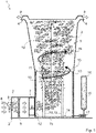
- figure 1 shows a schematic representation of a device 1 for reducing a pollutant load in a gas 2.
- the devices 1 shown in the exemplary embodiment are provided for the disinfection or sterilization of (room) air 2, without the invention being understood to be limited to this use.
- viruses, bacteria, spores or other organic and inorganic pollutants can be removed from the air 2 or at least rendered harmless by means of the device 1 according to the invention.
- the device 1 shown has a gas inlet 3 and two gas outlets 4 .
- a disinfection chamber 5 is arranged between the gas inlet 3 and the gas outlets 4 , through which a gas flow 6 running from the gas inlet 3 to the gas outlets 4 flows.
- the gas stream 6 is in figure 1 indicated by different arrows.
- the devices 1 of the exemplary embodiment have corresponding flow machines 7 for generating the gas flow 6 .
- This can in particular be an electronically controllable fan 7 .
- the flow machine(s) 7 can in principle be arranged at any point within the device 1, but preferably in the area of the gas inlet 3, as shown in the exemplary embodiments.
- the device 1 can, for example, also be arranged in an existing gas stream 6 in such a way that it flows through the disinfection space 5 .
- the device 1 can, for example, be integrated into an existing ventilation system (for example in a ventilation shaft of a ventilation or air conditioning system), in particular as described below in the context of figure 12 will be described in more detail.
- the device 1 can have ventilation grilles 8 at the gas inlet 3 and/or at the gas outlet 4 in order to block the ingress of objects into the device 1 in order to provide protection for the device 1 against damage or manipulation.
- various mechanical filters and/or activated carbon filters 9 can be arranged in the gas flow 6 within the device 1, which are able to remove coarser particles and/or already carry out an initial or additional cleaning. If necessary, the use of suspended matter filters can also be provided--however, this is not preferred since these allow only a limited gas throughput.
- Optional mechanical filters and/or activated carbon filters 9 are preferably arranged in the area of the gas inlet 3, in particular behind a ventilation grille 8, and preferably in front of the at least one turbomachine 7.
- the device 1 also has an aerosol generation arrangement 11 having a capillary material 10 within the disinfection space 5 .
- the gas stream 6 can flow through the aerosol generating arrangement 11 .
- the capillary material 10 of the aerosol generation arrangement 11 can be distributed as desired within the disinfection space 5, in particular in such a way that the capillary material 10 presents the gas 2 flowing past with as much surface area as possible.
- the aerosol generating arrangement 11 can also have at least one elongate body 13 formed from the capillary material 10 (in figure 1 shown in dashed lines), which extends through the disinfection space 5.
- a plurality of elongate bodies 13 are preferably provided, which are fixed together, for example at one of their ends (not shown).
- the capillary material 10 to extend into a liquid reservoir 14 in which a liquid oxidizing agent 15 is contained.
- the liquid reservoir 14 is formed at the lower end of the disinfection space 5, which is appropriately sealed. Due to the capillary properties of the capillary material 10, the oxidizing agent 15 is finally sucked up and rises in the capillary material 10 upwards until the surface of the capillary material 10 is completely free of the Oxidizing agent 15 is wetted. The gas 2 flowing past thus absorbs a corresponding quantity of the oxidizing agent 15 depending on the surface area provided.
- the liquid oxidant 15 is or comprises hydrogen peroxide.
- a hydrogen peroxide/water mixture can be provided, for example with a concentration of 5% hydrogen peroxide.
- a liquid tank 16 for the liquid oxidizing agent 15 can optionally be provided, which is fluidically connected to the liquid reservoir 14 .
- the liquid tank 16 can be a cartridge, for example, which the user of the device 1 can easily replace.
- a cartridge solution is in figure 1 implied; a fillable liquid tank 16, on the other hand, is shown in the exemplary embodiment of FIGS. 2 to 4, which will be described below.
- a pump 17 can be provided, for example a peristaltic pump or another advantageous metering pump.
- a liquid sensor can optionally be provided (not shown), which detects the presence of liquid in the liquid reservoir 14 and/or a liquid level in the liquid reservoir 14 and, if necessary, causes the pump 17 to supply further oxidizing agent 15 .
- the fluidic connection between an optional liquid tank 16 and the liquid reservoir 14 does not necessarily have to be provided in the area of the lower end of the device 1, as is indicated in the exemplary embodiments.
- provision can also be made to supply the liquid oxidizing agent 15 from the liquid tank 16 to the disinfection space 5 starting from a higher altitude and to let the oxidizing agent 15 run down, for example, along the capillary material 10 .
- additional spraying of the oxidizing agent 15 within the disinfection space 5 can also be provided, with excess oxidizing agent 15 being able to collect in the liquid reservoir 14 .
- At least one radiation source 18 for generating ionizing radiation, in particular UV-C radiation, is provided within the disinfection space 5 .
- the radiation source 18 can in particular be a UV-C tube or one or more UV-C light-emitting diodes.
- UV-C radiation alone offers an excellent germicidal effect.
- an extraordinarily strong disinfection effect can be brought about.
- the UV-C radiation can generate hydroxyl radicals, in particular in reaction with hydrogen peroxide (and/or, for example, the peroxycarboxylic acids mentioned above).
- the hydroxyl radical is an even stronger oxidizing agent than hydrogen peroxide and can reduce the pollution load within the gas 2 in a highly effective manner.
- the radiation source 18 is preferably designed and/or arranged in such a way that the ionizing radiation emits most of the disinfection space 5 , preferably the disinfection space 5 completely. It can also be provided that the length of the disinfection space 5 between the gas inlet 3 and the gas outlet 4 is greater than the diameter of the disinfection space 5.
- the disinfection space 5 preferably forms a linear channel for the gas flow 6. Optionally, however, the disinfection space 5 can also form one or more winding channels for the gas flow 6 .
- the aim of the measure mentioned above is in particular to ensure that the gas 2 stays in the disinfection chamber 5 for as long as possible, as a result of which the ionizing radiation, the hydrogen peroxide and/or the hydroxyl radicals reduce as many pollutants as possible, while at the same time having a high throughput of the gas 2.
- the radiation source 18 can be arranged at least in sections within the aerosol generation arrangement 11, as illustrated in the exemplary embodiments. In principle, however, it can also be provided that the radiation source 18 is arranged downstream of the aerosol generation arrangement 11 viewed in the direction of flow.
- the radiation source 18 does not necessarily have to be arranged centrally within the disinfection room 5, as shown in the exemplary embodiments.
- the radiation source 18 can, for example, also run adjacent to or adjacent to one of the side walls of the disinfection space 5 .
- a plurality of radiation sources 18 are preferably provided, for example two of the UV-C tubes 18 shown.
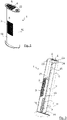
- the device 1 of the second exemplary embodiment has a single gas inlet 3 and a single gas outlet 4 which are each covered by a ventilation grille 8 .
- the gas inlet 3 or the ventilation grille 8 of the gas inlet 3 is arranged in an outer housing 19 of the device 1 .
- the device 1 also has an inner housing 20 which essentially delimits the disinfection space 5 .
- a gap 21 for guiding the gas flow 6 from the gas inlet 3 to a recess 12 in the inner housing 20 to the disinfection space 5 is provided between the outer housing 19 and the inner housing 20 .
- the offset between the ventilation grille 8 of the outer housing 19 and the recess 12 to the disinfection room 5 can be advantageous in order to shield the UV-C radiation or to prevent direct visual contact in the disinfection room 5 .
- a mechanical filter and / or activated carbon filter 9 preferably behind the ventilation grille 8 of the gas inlet 3, in particular replaceable or accessible to the user.
- two turbomachines 7 designed as fans are provided in a parallel arrangement in order to suck in the gas 2 starting from the gas inlet 3 and to push it through the disinfection space 5 until it finally escapes from the gas outlet 4 again.
- the capillary material 10 of the aerosol generating arrangement 11 is fixed on the inside to the inner walls of the disinfection space 5 and protrudes into the liquid reservoir 14 located in the lower end of the disinfection space 5 .
- the liquid oxidizing agent 15 is in the Figures 2 to 4 not shown.
- additional oxidizing agent 15 can optionally be supplied to the liquid reservoir 14 by means of a pump 17 .
- the liquid tank 16 has a cover that can be closed with a cover 22 Access opening that allows the user to supply more oxidizing agent 15.
- the liquid tank 16 can, for example, have a volume of one liter to 20 liters, preferably 2 liters to 15 liters, particularly preferably 5 liters to 10 liters.
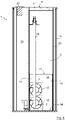
- UV-C tube 18 is provided.
- further UV-C radiation sources 18 can in principle also be provided, with the specific design being irrelevant.
- an air baffle 23 is provided (cf. figure 3 ) to direct the air 2 out of the disinfection room 5. Between the air baffles 23 is a shielding plate 24 (cf. also figure 3 ) provided to shield the UV-C radiation, for example a stainless steel sheet.
- FIGs 5 and 6 a third embodiment of the device 1 is shown, wherein figure 6 an individual view of the disinfection room 5 in a sectional view along line VI of figure 5 indicates; figure 7 12 represents a further variant of the disinfection space 5 of the third exemplary embodiment.
- the third exemplary embodiment essentially corresponds to the second exemplary embodiment, but has some optional, advantageous differentiating features.
- the device 1 of the third exemplary embodiment has a gas inlet 3 arranged in the lower area of the device 1, which in turn is covered by a ventilation grille 8 (cf. figure 5 ).
- the turbomachine 7 is indicated only schematically as a black box.
- the inner housing 20 delimits the disinfection space 5 .
- a recess 12 is provided in a base plate of the disinfection space 5 , on which a gas inlet nozzle 25 is placed and protrudes into the disinfection space 5 .
- This structure can also help to shield the UV-C radiation from the radiation source 18 or to prevent direct visual contact into the disinfection space 5 from the gas inlet 3 .
- the liquid reservoir 14 is formed in the lower area of the disinfection space 5 .
- the gas inlet nozzle 25 can ensure that the oxidizing agent 15 (in the Figures 5 to 7 not shown) does not escape from the disinfection space 5 through the recess 12 and, for example, penetrates into the turbomachine 7 and damages it.
- the capillary material 10 of the aerosol generating arrangement 11 can in turn be fixed on the inside to the inner walls of the disinfection space 5, as in figure 5 good to see.
- the capillary material 10 is arranged around the outer walls of the gas inlet socket 25 or is attached to the outside of the gas inlet socket 25 (in Figs Figures 6 and 7 indicated by dashed lines).
- the capillary material 10 is only arranged in the lower area of the disinfection space 5, it can be advantageous to generate turbulence in the gas 2 in this area, for example adjacent to the recess 12 and/or the gas inlet nozzle 25, in order to cause the gas 2 as efficiently as possible along the surface of the capillary material and to increase the dwell time of the gas 2 in the capillary material 10.
- guide plates not shown
- flow grids 26 cf. Figures 5 and 6
- lamella arrangements 27 cf. figure 7
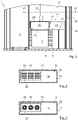
- a sound absorbing element 28 which can be arranged within the device 1 between the air inlet 3 and the air outlet 4 in order to reduce the noise emissions caused by the gas flow 6 .
- the sound absorbing element 28 is preferably arranged within the disinfection space 5 or in the aerosol generation arrangement 11 .
- the sound absorbing element 28 can optionally also be used as a replacement or supplement to the capillary material 10 in the aerosol generation arrangement 11 and can be wetted with the liquid oxidizing agent 15 .
- the sound absorbing element 28 can be accommodated in a retaining device 29 which forms at least one grid surface 30 which faces the gas flow 6 and behind which the sound absorbing element 28 is arranged.
- a retaining device 29 which forms at least one grid surface 30 which faces the gas flow 6 and behind which the sound absorbing element 28 is arranged.
- only one grid surface 30 is provided in each case; in the variant of figure 11 a wedge-shaped arrangement is provided by way of example, in which all outer surfaces of the retaining device 29 are provided with grid surfaces 30 .
- the sound absorbing element 28 can thus be accommodated in an advantageous manner within the double-walled restraint device 29 and still develop its sound-absorbing effect.
- the sound absorbing element 28 can be positioned in the gas flow 6 such that the gas flow 6 flows against the sound absorbing element 28 and is deflected by the sound absorbing element 28 .
- the sound absorbing element 28 can, for example, form an impact surface, as in FIGS Figures 8, 10 and 11 shown.
- the sound absorber element 28 can be installed on or in front of a kinking wall of the flow channel (cf. figure 8 ) or within the flow channel (cf. Figure 10 and 11 ) be arranged.
- the sound absorber element 28 can also be arranged running adjacent to an inner wall of the device 1, so that the gas flow 6 can flow laterally along the sound absorber element 28, as is shown in figure 9 is indicated.
- FIG 12 another system 31 for influencing a gas flow 6 is shown as an example, in which the device 1 described above can be advantageously used as an extension of a base unit 32 .
- the base unit 32 is shown by way of example as an extractor hood. In principle, however, it can be any ventilation system, including a circulating air system, and for example also an existing (air) cleaning system, such as a vacuum cleaner.
- the base unit 32 shown as an example has a turbomachine 7 for generating the gas flow 6 , the gas flow 6 being passed through an activated carbon filter 9 on the inlet side and then into an exhaust air duct 33 .
- the device 1 can, for example, be introduced into the exhaust air duct 33 as an extension.
- the existing gas flow 6 is utilized and introduced through the gas inlet 3 of the device 1 in order to exit the gas outlet 4 cleaned again after flowing through the disinfection chamber 5 or the aerosol generation arrangement 11 .
- the gas flow 6 cleaned by the device 1 can be discharged to the environment through a ventilation grille 34 of the base unit 32 .
- the exhaust air duct 33 can, for example, run through a building wall 35 at least in sections.
Landscapes
- Chemical & Material Sciences (AREA)
- Chemical Kinetics & Catalysis (AREA)
- Engineering & Computer Science (AREA)
- Health & Medical Sciences (AREA)
- Analytical Chemistry (AREA)
- General Chemical & Material Sciences (AREA)
- Oil, Petroleum & Natural Gas (AREA)
- Biomedical Technology (AREA)
- Environmental & Geological Engineering (AREA)
- Toxicology (AREA)
- Disinfection, Sterilisation Or Deodorisation Of Air (AREA)
- Physical Or Chemical Processes And Apparatus (AREA)
Applications Claiming Priority (1)
| Application Number | Priority Date | Filing Date | Title |
|---|---|---|---|
| DE102020130003.4A DE102020130003A1 (de) | 2020-11-13 | 2020-11-13 | Vorrichtung und Verfahren zur Reduzierung einer Schadstoffbelastung in einem Gas |
Publications (4)
| Publication Number | Publication Date |
|---|---|
| EP4000656A2 true EP4000656A2 (fr) | 2022-05-25 |
| EP4000656A3 EP4000656A3 (fr) | 2022-06-22 |
| EP4000656B1 EP4000656B1 (fr) | 2024-08-21 |
| EP4000656C0 EP4000656C0 (fr) | 2024-08-21 |
Family
ID=78516717
Family Applications (1)
| Application Number | Title | Priority Date | Filing Date |
|---|---|---|---|
| EP21206366.3A Active EP4000656B1 (fr) | 2020-11-13 | 2021-11-04 | Dispositif et procédé de réduction de la charge en substances nocives dans un gaz |
Country Status (2)
| Country | Link |
|---|---|
| EP (1) | EP4000656B1 (fr) |
| DE (1) | DE102020130003A1 (fr) |
Citations (3)
| Publication number | Priority date | Publication date | Assignee | Title |
|---|---|---|---|---|
| US20070217944A1 (en) | 2003-01-06 | 2007-09-20 | The Johns Hopkins University | Hydroxyl free radical-induced decontamination of airborne spores, viruses and bacteria in a dynamic system |
| WO2015059336A1 (fr) | 2013-10-23 | 2015-04-30 | John Morton Juaneda | Dispositif de purification d'air par émission de radicaux hydroxyle |
| CN208809155U (zh) | 2018-03-20 | 2019-05-03 | 张树武 | 传染病病房空气消毒装置 |
Family Cites Families (6)
| Publication number | Priority date | Publication date | Assignee | Title |
|---|---|---|---|---|
| DE3630710A1 (de) * | 1986-09-10 | 1988-03-24 | Vorwerk Co Interholding | Absorptionsschalldaempfer |
| US20040005252A1 (en) * | 2001-07-20 | 2004-01-08 | Siess Harold Edward | Preventing the transmission of disease |
| WO2007064188A1 (fr) * | 2005-12-01 | 2007-06-07 | Sara Lee/De N.V. | Systeme de distribution d'arome |
| JP5241135B2 (ja) * | 2006-05-25 | 2013-07-17 | 三洋電機株式会社 | 空気除菌装置 |
| RU2594088C1 (ru) * | 2015-09-08 | 2016-08-10 | Мария Олеговна Стареева | Активный глушитель шума промышленного пылесоса |
| JP2019523038A (ja) * | 2016-06-17 | 2019-08-22 | ステリファー・メディカル・インコーポレイテッドSterifre Medical, Inc. | 滅菌、消毒、衛生化、除染および治療の装置、システム、ならびに方法 |
-
2020
- 2020-11-13 DE DE102020130003.4A patent/DE102020130003A1/de active Pending
-
2021
- 2021-11-04 EP EP21206366.3A patent/EP4000656B1/fr active Active
Patent Citations (3)
| Publication number | Priority date | Publication date | Assignee | Title |
|---|---|---|---|---|
| US20070217944A1 (en) | 2003-01-06 | 2007-09-20 | The Johns Hopkins University | Hydroxyl free radical-induced decontamination of airborne spores, viruses and bacteria in a dynamic system |
| WO2015059336A1 (fr) | 2013-10-23 | 2015-04-30 | John Morton Juaneda | Dispositif de purification d'air par émission de radicaux hydroxyle |
| CN208809155U (zh) | 2018-03-20 | 2019-05-03 | 张树武 | 传染病病房空气消毒装置 |
Also Published As
| Publication number | Publication date |
|---|---|
| EP4000656B1 (fr) | 2024-08-21 |
| EP4000656A3 (fr) | 2022-06-22 |
| EP4000656C0 (fr) | 2024-08-21 |
| DE102020130003A1 (de) | 2022-05-19 |
Similar Documents
| Publication | Publication Date | Title |
|---|---|---|
| DE60133086T3 (de) | Luftbehandlungsgerät | |
| EP2344283B1 (fr) | Brosse de nettoyage pour aspirateur | |
| DE102005003923A1 (de) | Vorrichtung und Verfahren zum Entkeimen von Raumluft | |
| DE102016117797A1 (de) | Luftreinigungsvorrichtung | |
| DE1965022B2 (de) | Apparat zur raumdesinfektion und/ oder -sterilisation | |
| AT520295A4 (de) | Reinigungsvorrichtung | |
| DE102018125596A1 (de) | Vorrichtung und Verfahren zur Entkeimung eines Gases oder Gasgemisches mit UVC-Strahlung | |
| DE102015116199A1 (de) | Lüftungsvorrichtung zur Lüftung eines Innenraumes einer Stallung | |
| WO2005018692A1 (fr) | Dispositif de degermination d'un flux d'air a l'aide de lumiere uv | |
| DE19513943A1 (de) | Verfahren und Vorrichtung zur Verbesserung der Raumluftqualität | |
| EP3497375B1 (fr) | Climatiseur pour humidifier de l'air ambiant avec de l'eau minéralisée | |
| EP3999129A1 (fr) | Appareil de sédimentation et d'oxydation de poussières fines, d'aérosols et de charges organiques comme des virus dans un dispositif, et pour le traitement électrostatique et électrochimique ou photochimique de l'air fourni par le dispositif à une pièce pour des processus analogiques dans la pièce | |
| EP4000656B1 (fr) | Dispositif et procédé de réduction de la charge en substances nocives dans un gaz | |
| DE202006020800U1 (de) | Luftdesinfektionsvorrichtung | |
| DE102020109727A1 (de) | Beatmungsgerät | |
| EP0878670A2 (fr) | Dispositif de travail, en particulier établi de sécurité | |
| EP3406977A1 (fr) | Purificateur d'air intérieur | |
| DE202020105930U1 (de) | Dunstabzug | |
| CH555679A (fr) | ||
| DE202013012016U1 (de) | Belüftungsvorrichtung | |
| EP3964760A1 (fr) | Système de traitement de l'air permettant de nettoyer l'air ambiant | |
| DE202021100771U1 (de) | Vorrichtung zum Behandeln, insbesondere Entkeimen oder Desinfizieren von Luft, insbesondere Raumluft, oder Oberflächen | |
| DE1954336A1 (de) | Dunstabzugshaube | |
| DE102021105374A1 (de) | Luftaufbereitungsapparat | |
| EP4171667B1 (fr) | Traitement de gaz |
Legal Events
| Date | Code | Title | Description |
|---|---|---|---|
| PUAI | Public reference made under article 153(3) epc to a published international application that has entered the european phase |
Free format text: ORIGINAL CODE: 0009012 |
|
| STAA | Information on the status of an ep patent application or granted ep patent |
Free format text: STATUS: THE APPLICATION HAS BEEN PUBLISHED |
|
| PUAL | Search report despatched |
Free format text: ORIGINAL CODE: 0009013 |
|
| AK | Designated contracting states |
Kind code of ref document: A2 Designated state(s): AL AT BE BG CH CY CZ DE DK EE ES FI FR GB GR HR HU IE IS IT LI LT LU LV MC MK MT NL NO PL PT RO RS SE SI SK SM TR |
|
| AK | Designated contracting states |
Kind code of ref document: A3 Designated state(s): AL AT BE BG CH CY CZ DE DK EE ES FI FR GB GR HR HU IE IS IT LI LT LU LV MC MK MT NL NO PL PT RO RS SE SI SK SM TR |
|
| RIC1 | Information provided on ipc code assigned before grant |
Ipc: A47L 9/00 20060101ALN20220519BHEP Ipc: B08B 15/02 20060101ALN20220519BHEP Ipc: A61L 9/20 20060101ALN20220519BHEP Ipc: A61L 9/14 20060101ALI20220519BHEP Ipc: A61L 9/12 20060101AFI20220519BHEP |
|
| STAA | Information on the status of an ep patent application or granted ep patent |
Free format text: STATUS: REQUEST FOR EXAMINATION WAS MADE |
|
| 17P | Request for examination filed |
Effective date: 20221109 |
|
| RBV | Designated contracting states (corrected) |
Designated state(s): AL AT BE BG CH CY CZ DE DK EE ES FI FR GB GR HR HU IE IS IT LI LT LU LV MC MK MT NL NO PL PT RO RS SE SI SK SM TR |
|
| STAA | Information on the status of an ep patent application or granted ep patent |
Free format text: STATUS: EXAMINATION IS IN PROGRESS |
|
| 17Q | First examination report despatched |
Effective date: 20230731 |
|
| REG | Reference to a national code |
Ref country code: DE Ref legal event code: R079 Free format text: PREVIOUS MAIN CLASS: A61L0009120000 Ipc: B01D0047020000 Ref country code: DE Ref legal event code: R079 Ref document number: 502021004845 Country of ref document: DE Free format text: PREVIOUS MAIN CLASS: A61L0009120000 Ipc: B01D0047020000 |
|
| GRAP | Despatch of communication of intention to grant a patent |
Free format text: ORIGINAL CODE: EPIDOSNIGR1 |
|
| STAA | Information on the status of an ep patent application or granted ep patent |
Free format text: STATUS: GRANT OF PATENT IS INTENDED |
|
| RIC1 | Information provided on ipc code assigned before grant |
Ipc: B01D 50/60 20220101ALN20240430BHEP Ipc: B01D 46/10 20060101ALN20240430BHEP Ipc: B01D 46/00 20220101ALN20240430BHEP Ipc: A61L 9/20 20060101ALN20240430BHEP Ipc: B01D 53/72 20060101ALI20240430BHEP Ipc: B01D 53/00 20060101ALI20240430BHEP Ipc: B01D 47/02 20060101AFI20240430BHEP |
|
| INTG | Intention to grant announced |
Effective date: 20240527 |
|
| GRAS | Grant fee paid |
Free format text: ORIGINAL CODE: EPIDOSNIGR3 |
|
| GRAA | (expected) grant |
Free format text: ORIGINAL CODE: 0009210 |
|
| STAA | Information on the status of an ep patent application or granted ep patent |
Free format text: STATUS: THE PATENT HAS BEEN GRANTED |
|
| AK | Designated contracting states |
Kind code of ref document: B1 Designated state(s): AL AT BE BG CH CY CZ DE DK EE ES FI FR GB GR HR HU IE IS IT LI LT LU LV MC MK MT NL NO PL PT RO RS SE SI SK SM TR |
|
| REG | Reference to a national code |
Ref country code: GB Ref legal event code: FG4D Free format text: NOT ENGLISH |
|
| REG | Reference to a national code |
Ref country code: CH Ref legal event code: EP |
|
| REG | Reference to a national code |
Ref country code: IE Ref legal event code: FG4D Free format text: LANGUAGE OF EP DOCUMENT: GERMAN |
|
| REG | Reference to a national code |
Ref country code: DE Ref legal event code: R096 Ref document number: 502021004845 Country of ref document: DE |
|
| U01 | Request for unitary effect filed |
Effective date: 20240821 |
|
| U07 | Unitary effect registered |
Designated state(s): AT BE BG DE DK EE FI FR IT LT LU LV MT NL PT RO SE SI Effective date: 20240902 |
|
| U20 | Renewal fee for the european patent with unitary effect paid |
Year of fee payment: 4 Effective date: 20240925 |
|
| U1N | Appointed representative for the unitary patent procedure changed after the registration of the unitary effect |
Representative=s name: LORENZ & KOLLEGEN; DE |
|
| PG25 | Lapsed in a contracting state [announced via postgrant information from national office to epo] |
Ref country code: NO Free format text: LAPSE BECAUSE OF FAILURE TO SUBMIT A TRANSLATION OF THE DESCRIPTION OR TO PAY THE FEE WITHIN THE PRESCRIBED TIME-LIMIT Effective date: 20241121 |
|
| PG25 | Lapsed in a contracting state [announced via postgrant information from national office to epo] |
Ref country code: GR Free format text: LAPSE BECAUSE OF FAILURE TO SUBMIT A TRANSLATION OF THE DESCRIPTION OR TO PAY THE FEE WITHIN THE PRESCRIBED TIME-LIMIT Effective date: 20241122 Ref country code: PL Free format text: LAPSE BECAUSE OF FAILURE TO SUBMIT A TRANSLATION OF THE DESCRIPTION OR TO PAY THE FEE WITHIN THE PRESCRIBED TIME-LIMIT Effective date: 20240821 |
|
| PG25 | Lapsed in a contracting state [announced via postgrant information from national office to epo] |
Ref country code: IS Free format text: LAPSE BECAUSE OF FAILURE TO SUBMIT A TRANSLATION OF THE DESCRIPTION OR TO PAY THE FEE WITHIN THE PRESCRIBED TIME-LIMIT Effective date: 20241221 |
|
| PG25 | Lapsed in a contracting state [announced via postgrant information from national office to epo] |
Ref country code: HR Free format text: LAPSE BECAUSE OF FAILURE TO SUBMIT A TRANSLATION OF THE DESCRIPTION OR TO PAY THE FEE WITHIN THE PRESCRIBED TIME-LIMIT Effective date: 20240821 |
|
| PG25 | Lapsed in a contracting state [announced via postgrant information from national office to epo] |
Ref country code: ES Free format text: LAPSE BECAUSE OF FAILURE TO SUBMIT A TRANSLATION OF THE DESCRIPTION OR TO PAY THE FEE WITHIN THE PRESCRIBED TIME-LIMIT Effective date: 20240821 Ref country code: RS Free format text: LAPSE BECAUSE OF FAILURE TO SUBMIT A TRANSLATION OF THE DESCRIPTION OR TO PAY THE FEE WITHIN THE PRESCRIBED TIME-LIMIT Effective date: 20241121 |
|
| PG25 | Lapsed in a contracting state [announced via postgrant information from national office to epo] |
Ref country code: RS Free format text: LAPSE BECAUSE OF FAILURE TO SUBMIT A TRANSLATION OF THE DESCRIPTION OR TO PAY THE FEE WITHIN THE PRESCRIBED TIME-LIMIT Effective date: 20241121 Ref country code: PL Free format text: LAPSE BECAUSE OF FAILURE TO SUBMIT A TRANSLATION OF THE DESCRIPTION OR TO PAY THE FEE WITHIN THE PRESCRIBED TIME-LIMIT Effective date: 20240821 Ref country code: NO Free format text: LAPSE BECAUSE OF FAILURE TO SUBMIT A TRANSLATION OF THE DESCRIPTION OR TO PAY THE FEE WITHIN THE PRESCRIBED TIME-LIMIT Effective date: 20241121 Ref country code: IS Free format text: LAPSE BECAUSE OF FAILURE TO SUBMIT A TRANSLATION OF THE DESCRIPTION OR TO PAY THE FEE WITHIN THE PRESCRIBED TIME-LIMIT Effective date: 20241221 Ref country code: HR Free format text: LAPSE BECAUSE OF FAILURE TO SUBMIT A TRANSLATION OF THE DESCRIPTION OR TO PAY THE FEE WITHIN THE PRESCRIBED TIME-LIMIT Effective date: 20240821 Ref country code: GR Free format text: LAPSE BECAUSE OF FAILURE TO SUBMIT A TRANSLATION OF THE DESCRIPTION OR TO PAY THE FEE WITHIN THE PRESCRIBED TIME-LIMIT Effective date: 20241122 Ref country code: ES Free format text: LAPSE BECAUSE OF FAILURE TO SUBMIT A TRANSLATION OF THE DESCRIPTION OR TO PAY THE FEE WITHIN THE PRESCRIBED TIME-LIMIT Effective date: 20240821 |
|
| PG25 | Lapsed in a contracting state [announced via postgrant information from national office to epo] |
Ref country code: SM Free format text: LAPSE BECAUSE OF FAILURE TO SUBMIT A TRANSLATION OF THE DESCRIPTION OR TO PAY THE FEE WITHIN THE PRESCRIBED TIME-LIMIT Effective date: 20240821 |
|
| PG25 | Lapsed in a contracting state [announced via postgrant information from national office to epo] |
Ref country code: CZ Free format text: LAPSE BECAUSE OF FAILURE TO SUBMIT A TRANSLATION OF THE DESCRIPTION OR TO PAY THE FEE WITHIN THE PRESCRIBED TIME-LIMIT Effective date: 20240821 |
|
| PG25 | Lapsed in a contracting state [announced via postgrant information from national office to epo] |
Ref country code: SK Free format text: LAPSE BECAUSE OF FAILURE TO SUBMIT A TRANSLATION OF THE DESCRIPTION OR TO PAY THE FEE WITHIN THE PRESCRIBED TIME-LIMIT Effective date: 20240821 |
|
| PLBE | No opposition filed within time limit |
Free format text: ORIGINAL CODE: 0009261 |
|
| STAA | Information on the status of an ep patent application or granted ep patent |
Free format text: STATUS: NO OPPOSITION FILED WITHIN TIME LIMIT |
|
| REG | Reference to a national code |
Ref country code: CH Ref legal event code: PL |
|
| PG25 | Lapsed in a contracting state [announced via postgrant information from national office to epo] |
Ref country code: MC Free format text: LAPSE BECAUSE OF FAILURE TO SUBMIT A TRANSLATION OF THE DESCRIPTION OR TO PAY THE FEE WITHIN THE PRESCRIBED TIME-LIMIT Effective date: 20240821 |
|
| REG | Reference to a national code |
Ref country code: CH Ref legal event code: PL |
|
| PG25 | Lapsed in a contracting state [announced via postgrant information from national office to epo] |
Ref country code: CH Free format text: LAPSE BECAUSE OF NON-PAYMENT OF DUE FEES Effective date: 20241130 |
|
| 26N | No opposition filed |
Effective date: 20250522 |
|
| PG25 | Lapsed in a contracting state [announced via postgrant information from national office to epo] |
Ref country code: IE Free format text: LAPSE BECAUSE OF NON-PAYMENT OF DUE FEES Effective date: 20241104 |
|
| U20 | Renewal fee for the european patent with unitary effect paid |
Year of fee payment: 5 Effective date: 20251105 |
|
| PG25 | Lapsed in a contracting state [announced via postgrant information from national office to epo] |
Ref country code: HU Free format text: LAPSE BECAUSE OF FAILURE TO SUBMIT A TRANSLATION OF THE DESCRIPTION OR TO PAY THE FEE WITHIN THE PRESCRIBED TIME-LIMIT; INVALID AB INITIO Effective date: 20211104 |
|
| PG25 | Lapsed in a contracting state [announced via postgrant information from national office to epo] |
Ref country code: CY Free format text: LAPSE BECAUSE OF FAILURE TO SUBMIT A TRANSLATION OF THE DESCRIPTION OR TO PAY THE FEE WITHIN THE PRESCRIBED TIME-LIMIT; INVALID AB INITIO Effective date: 20211104 |