EP2657044A1 - Pneumatique - Google Patents
Pneumatique Download PDFInfo
- Publication number
- EP2657044A1 EP2657044A1 EP11851185.6A EP11851185A EP2657044A1 EP 2657044 A1 EP2657044 A1 EP 2657044A1 EP 11851185 A EP11851185 A EP 11851185A EP 2657044 A1 EP2657044 A1 EP 2657044A1
- Authority
- EP
- European Patent Office
- Prior art keywords
- thermoplastic resin
- sheet
- tip
- resin composition
- elastomer
- Prior art date
- Legal status (The legal status is an assumption and is not a legal conclusion. Google has not performed a legal analysis and makes no representation as to the accuracy of the status listed.)
- Granted
Links
Images


Classifications
-
- B—PERFORMING OPERATIONS; TRANSPORTING
- B60—VEHICLES IN GENERAL
- B60C—VEHICLE TYRES; TYRE INFLATION; TYRE CHANGING; CONNECTING VALVES TO INFLATABLE ELASTIC BODIES IN GENERAL; DEVICES OR ARRANGEMENTS RELATED TO TYRES
- B60C19/00—Tyre parts or constructions not otherwise provided for
-
- B—PERFORMING OPERATIONS; TRANSPORTING
- B29—WORKING OF PLASTICS; WORKING OF SUBSTANCES IN A PLASTIC STATE IN GENERAL
- B29D—PRODUCING PARTICULAR ARTICLES FROM PLASTICS OR FROM SUBSTANCES IN A PLASTIC STATE
- B29D30/00—Producing pneumatic or solid tyres or parts thereof
- B29D30/06—Pneumatic tyres or parts thereof (e.g. produced by casting, moulding, compression moulding, injection moulding, centrifugal casting)
- B29D30/08—Building tyres
- B29D30/20—Building tyres by the flat-tyre method, i.e. building on cylindrical drums
- B29D30/30—Applying the layers; Guiding or stretching the layers during application
- B29D30/3007—Applying the layers; Guiding or stretching the layers during application by feeding a sheet perpendicular to the drum axis and joining the ends to form an annular element
-
- B—PERFORMING OPERATIONS; TRANSPORTING
- B29—WORKING OF PLASTICS; WORKING OF SUBSTANCES IN A PLASTIC STATE IN GENERAL
- B29D—PRODUCING PARTICULAR ARTICLES FROM PLASTICS OR FROM SUBSTANCES IN A PLASTIC STATE
- B29D30/00—Producing pneumatic or solid tyres or parts thereof
- B29D30/06—Pneumatic tyres or parts thereof (e.g. produced by casting, moulding, compression moulding, injection moulding, centrifugal casting)
- B29D30/08—Building tyres
- B29D30/20—Building tyres by the flat-tyre method, i.e. building on cylindrical drums
- B29D30/30—Applying the layers; Guiding or stretching the layers during application
- B29D30/305—Applying the layers; Guiding or stretching the layers during application by feeding cut-to-length pieces in a direction parallel to the drum axis and placing the pieces side-by-side to form an annular element
-
- B—PERFORMING OPERATIONS; TRANSPORTING
- B60—VEHICLES IN GENERAL
- B60C—VEHICLE TYRES; TYRE INFLATION; TYRE CHANGING; CONNECTING VALVES TO INFLATABLE ELASTIC BODIES IN GENERAL; DEVICES OR ARRANGEMENTS RELATED TO TYRES
- B60C1/00—Tyres characterised by the chemical composition or the physical arrangement or mixture of the composition
- B60C1/0008—Compositions of the inner liner
-
- B—PERFORMING OPERATIONS; TRANSPORTING
- B60—VEHICLES IN GENERAL
- B60C—VEHICLE TYRES; TYRE INFLATION; TYRE CHANGING; CONNECTING VALVES TO INFLATABLE ELASTIC BODIES IN GENERAL; DEVICES OR ARRANGEMENTS RELATED TO TYRES
- B60C5/00—Inflatable pneumatic tyres or inner tubes
- B60C5/12—Inflatable pneumatic tyres or inner tubes without separate inflatable inserts, e.g. tubeless tyres with transverse section open to the rim
- B60C5/14—Inflatable pneumatic tyres or inner tubes without separate inflatable inserts, e.g. tubeless tyres with transverse section open to the rim with impervious liner or coating on the inner wall of the tyre
-
- B—PERFORMING OPERATIONS; TRANSPORTING
- B29—WORKING OF PLASTICS; WORKING OF SUBSTANCES IN A PLASTIC STATE IN GENERAL
- B29D—PRODUCING PARTICULAR ARTICLES FROM PLASTICS OR FROM SUBSTANCES IN A PLASTIC STATE
- B29D30/00—Producing pneumatic or solid tyres or parts thereof
- B29D30/06—Pneumatic tyres or parts thereof (e.g. produced by casting, moulding, compression moulding, injection moulding, centrifugal casting)
- B29D30/0681—Parts of pneumatic tyres; accessories, auxiliary operations
- B29D2030/0682—Inner liners
-
- B—PERFORMING OPERATIONS; TRANSPORTING
- B60—VEHICLES IN GENERAL
- B60C—VEHICLE TYRES; TYRE INFLATION; TYRE CHANGING; CONNECTING VALVES TO INFLATABLE ELASTIC BODIES IN GENERAL; DEVICES OR ARRANGEMENTS RELATED TO TYRES
- B60C5/00—Inflatable pneumatic tyres or inner tubes
- B60C5/12—Inflatable pneumatic tyres or inner tubes without separate inflatable inserts, e.g. tubeless tyres with transverse section open to the rim
- B60C5/14—Inflatable pneumatic tyres or inner tubes without separate inflatable inserts, e.g. tubeless tyres with transverse section open to the rim with impervious liner or coating on the inner wall of the tyre
- B60C2005/147—Inflatable pneumatic tyres or inner tubes without separate inflatable inserts, e.g. tubeless tyres with transverse section open to the rim with impervious liner or coating on the inner wall of the tyre characterised by the joint or splice
-
- Y—GENERAL TAGGING OF NEW TECHNOLOGICAL DEVELOPMENTS; GENERAL TAGGING OF CROSS-SECTIONAL TECHNOLOGIES SPANNING OVER SEVERAL SECTIONS OF THE IPC; TECHNICAL SUBJECTS COVERED BY FORMER USPC CROSS-REFERENCE ART COLLECTIONS [XRACs] AND DIGESTS
- Y10—TECHNICAL SUBJECTS COVERED BY FORMER USPC
- Y10T—TECHNICAL SUBJECTS COVERED BY FORMER US CLASSIFICATION
- Y10T152/00—Resilient tires and wheels
- Y10T152/10—Tires, resilient
- Y10T152/10495—Pneumatic tire or inner tube
Definitions
- the present invention relates to a pneumatic tire.
- the present invention relates to a pneumatic tire including an inner liner layer formed as follows.
- a laminate sheet is obtained by laminating: a sheet made from a thermoplastic resin or a thermoplastic resin composition which is a blend of the thermoplastic resin and an elastomer; and a rubber to be bonded by curing to the thermoplastic resin or the thermoplastic resin composition.
- the laminate sheet is cut to a predetermined length. End portions of the laminate sheet are spliced together.
- the resultant product is cured and molded into the inner liner sheet.
- This pneumatic tire does not develop cracks around a splice portion of the spliced laminate sheet (inner liner layer) after the pneumatic tire starts to be used for driving, and accordingly has excellent durability.
- Patent Document 1 proposes a sheet-shaped object, formed from a thermoplastic resin or a thermoplastic resin composition which is a blend of the thermoplastic resin and an elastomer, as an inner liner of a pneumatic tire.
- a laminate sheet is formed which includes: a sheet made from a thermoplastic resin or a thermoplastic resin composition which is a blend of the thermoplastic resin and an elastomer; and a rubber (tie rubber) sheet to be bonded by curing to the thermoplastic resin or the thermoplastic resin which is the blend of the thermoplastic resin and the elastomer.
- the laminate sheet is wound around a tire building drum, and is subjected to lap-splicing. The resultant product is subsequently subjected to a curing and molding process.
- a tire is manufactured by: pulling out a predetermined length of the laminate sheet including the thermoplastic resin or the thermoplastic resin composition which is the blend of the thermoplastic resin and the elastomer and the tie rubber layer, which has been wound into a rolled shape, from its roll and cutting out the laminate sheet; winding the laminate sheet around the tire building drum; lap-splicing the laminate sheet on the drum; and further curing and molding the resultant product.
- the components constituting the inner liner namely, the sheet made from the thermoplastic resin or the thermoplastic resin composition, and the tie rubber sheet bonded by curing to the sheet made from the thermoplastic resin or the plastic resin composition, may be detached from each other after the tire starts to be used for driving.
- a laminate sheet 1 including: a sheet 2 made from a thermoplastic resin or a thermoplastic resin composition which is a blend of the thermoplastic resin and an elastomer; and a tie rubber layer 3, is cut to a desired size (length) with an edged tool, for example. Then, on a tire building drum, two end portions of the laminate sheet 1 are spliced together, with a lap splice portion S defined at the two ends thereof, into a way that the laminate sheet 1 is formed into an annular shape.
- the laminate sheet 1 is formed into an annular shape by splicing its two end portions together.
- the laminate sheets 1 are formed into an annular shape by splicing their end portions to one another.
- an inner liner layer 10 which includes: the sheet 2 made from the thermoplastic resin or the thermoplastic resin composition which is the blend of the thermoplastic resin and the elastomer; and the tie rubber layer 3.
- the sheet 2 made from the thermoplastic resin or the thermoplastic resin composition is exposed, and a portion where the sheet 2 is buried in the tie rubber layer.
- an object of the present invention is to provide a pneumatic tire formed as follows.
- a laminate sheet is formed by laminating: a sheet made from a thermoplastic resin or a thermoplastic resin composition which is a blend of the thermoplastic resin and an elastomer; and a rubber to be bonded by curing to the thermoplastic resin or the thermoplastic resin composition.
- a strip of the laminate sheet is obtained by cutting the laminate sheet to a predetermined length.
- the sheet made from the thermoplastic resin or the thermoplastic resin composition which is the blend of the thermoplastic resin and the elastomer, and the rubber to be bonded by curing to the thermoplastic resin or the thermoplastic resin composition are cut to the predetermined length, respectively.
- a strip of the laminate sheet is obtained by laminating the thus-cut pieces of the sheet and the rubber. End portions of the strip of the laminate sheet are lap-spliced together, and the resultant product is subjected to a curing and molding process.
- the pneumatic tire is built to include an inner liner layer formed from the laminate sheet. After the thus-provided pneumatic tire starts to be used for driving, no cracks occur in the vicinity of a splice portion of the spliced laminate sheet (inner liner layer). Accordingly, the pneumatic tire has excellent durability.
- a pneumatic tire according to the present invention includes the following configuration of section (1).
- a pneumatic tire including an inner liner layer 10 which is formed by lap-splicing end portions of a laminate sheet 1 obtained by laminating a sheet 2 and a rubber 3, the sheet 2 made from a thermoplastic resin or a thermoplastic resin composition which is a blend of the thermoplastic resin and an elastomer, and the rubber 3 to be bonded by curing to the thermoplastic resin or the thermoplastic resin composition, characterized in that a sheet with end portions each having a tip subjected to a tip sharpening process is used as the sheet 2 made from the thermoplastic resin or the thermoplastic resin composition which is the blend of the thermoplastic resin and the elastomer.
- the pneumatic tire of the present invention preferably includes any one of the following configurations of sections (2) to (7).
- t represents an average thickness ( ⁇ m), in a tire circumferential direction, of a tip-sharpening-unprocessed part of the sheet 2 made from the thermoplastic resin or the thermoplastic resin composition which is the blend of the thermoplastic resin and the elastomer
- T represents the thickness ( ⁇ m) of the sheet 2 in the location inward by the length (t ⁇ 1/3 from the tip of the sheet 2 made from the thermoplastic resin or the thermoplastic resin composition which is the blend of the thermoplastic resin and the elastomer.
- thermoplastic resin composition which is the blend of the thermoplastic resin and the elastomer, and on a surface of the tip-sharpening-processed tip, the elastomer is covered with a film of the thermoplastic resin.
- (7) The pneumatic tire of any one of sections (1) to (6), characterized in that one or a plurality of the laminate sheets 1 are used, and the inner liner layer 10 is formed by lap-splicing two end portions of the one laminate sheet 1, or by lap-splicing corresponding end portions of the plurality of laminate sheets 1 to one another.
- the present invention of claim 1 provides the pneumatic tire having excellent durability in which the components constituting the inner liner layer, namely, the sheet made from the thermoplastic resin or the thermoplastic resin composition, and the tie rubber sheet bonded by curing to the sheet made from thermoplastic resin or the thermoplastic resin composition, are prevented from detachment from each other after the tire starts to be used for driving.
- the pneumatic tire of any one of claims 2 to 6 has the effects of the present invention of claim 1, and can obtain the effects more reliably and more effectively at the same time.
- the pneumatic tire of claim 7 provides the pneumatic tire having excellent durability which has the effects of the present invention of the claim 1, when the inner liner layer 10 is formed by: using the one or multiple laminate sheets; lap-splicing the end portions (the two end portions of the one laminate sheet, or the end portions of the multiple laminate sheets) to one another; and forming the one or multiple laminate sheets into an annular shape.
- the pneumatic tire of the present invention is a pneumatic tire whose inner liner layer 10 is formed by lap-splicing end portions of a laminate sheet 1 obtained by laminating: a sheet 2 made from a thermoplastic resin or a thermoplastic resin composition which is a blend of a thermoplastic resin and an elastomer; and a rubber 3 to be bonded by curing to the thermoplastic resin or the thermoplastic resin composition.
- the pneumatic tire is characterized in that, one whose tips are subjected to a tip sharpening process is used as the sheet 2 made from the thermoplastic resin or the thermoplastic resin composition which is the blend of the thermoplastic resin and the elastomer.
- the inventors have examined causes of a problem with pneumatic tires produced by a conventional method from various aspects.
- the problem is that the components constituting the inner liner layer, namely, the sheet made from the thermoplastic resin or the thermoplastic resin composition which is the blend of the thermoplastic resin and the elastomer, and the tie rubber sheet bonded by curing to the sheet made from the thermoplastic resin or the thermoplastic resin composition.
- the inventors have obtained the following findings.
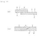
- the laminate sheet 1 is prepared by a usual method, large stress occurs in a rubber portion sandwiched between vertically-stacked end portions of the sheet 2 with large rigidity, made from the thermoplastic resin or the thermoplastic resin composition which is the blend of the thermoplastic resin and the elastomer, near a lap-splice portion S between the two ends of the laminate sheet 1 shown in Figs. 2 (a) and 2 (b) ; and for this reason, the detachment takes place as cracks occur and become larger in the vicinity 4 and the like of the tip portions of the sheet 2 made from the thermoplastic resin or the thermoplastic resin composition.
- one provided with parts 5 resulting from a tip sharpening process performed in the vicinity of each of its tips is prepared as the sheet 2 made from the thermoplastic resin or the thermoplastic resin composition which is the blend of the thermoplastic resin and the elastomer when the laminate sheet 1 is prepared by being cut to a predetermined length.
- the area of an interface between the sheet 2 and the rubber potion 3 becomes larger, the stress is dispersed.
- the stress which occurs in the rubber portion 3 sandwiched between the end portions of the sheet 2 becomes smaller and dispersed, and is accordingly relaxed. After the tire starts to be used, this is effective in preventing the occurrence of a phenomenon of detachment between the sheet 2 made from the thermoplastic resin or the thermoplastic resin composition and the tie rubber sheet 3 bonded by curing to the sheet 2.
- a section of the laminate sheet 1 has a cut end surface which is perpendicular to the flat-surface direction of the sheet 2 when viewed in the widthwise direction of the sheet ( Fig. 2(a) ).
- the expression that the tip of the sheet 2 made from the thermoplastic resin or the thermoplastic resin composition which is the blend of the thermoplastic resin and the elastomer "is subjected to the tip sharpening process" means that, as shown in Figs.
- the cut end surface of the sheet 2 of the present invention includes the tip-sharpening-processed part 5 which is tapered toward the tip as the result of the tip sharpening process.
- the expression means that, for the purpose of making the sheet 2 have such a lateral surface shape, the tip end of the sheet 2 is subjected to any of a physical treatment, a chemical treatment, a combination of the two treatments, a combination of the two treatments and a thermal treatment, and the like.
- the process may be performed at the same time as when the laminate sheet 1 is cut to a predetermined length adapted to desired lap-splicing, or after the laminate sheet 1 is cut to the predetermined length.
- the tip sharpening process may be performed on the tip portion of the sheet 2 made from the thermoplastic resin or the thermoplastic resin composition, which is the blend of the thermoplastic resin and the elastomer, and/or a tip portion of the rubber 3 in a step before the laminate sheet is formed. Thereafter, the laminate sheet 1 may be formed by stacking and bonding the sheet 2 and the rubber 3.
- the tip-sharpened shape can be realized in the tip portion of the laminate sheet, and the above-described effects of dispersing and relaxing the stress can be obtained.
- the tip sharpening process may be performed after the tire is cured and molded. Particularly in a case where the tip sharpening process mainly includes a physical treatment as described later, performance of the tip sharpening process after the tire is cured and molded is advantageous from the viewpoint of ease and accuracy in performing the process.
- the tip sharpening process performed on the tip of the sheet 2 exerts its effect even when the tip is only formed into the somewhat rounded shape. Nevertheless, especially in order to stably obtain a higher effect, it is desirable that the tip sharpening process be carried out at a location inward by a length (t ⁇ 1/3 from the tip of the sheet 2 made from the thermoplastic resin or the thermoplastic resin composition which is the blend of the thermoplastic resin and the elastomer, and with a thickness T ( ⁇ m) in a way that the thickness T has a relationship satisfying 0.1t ⁇ T ⁇ 0.8t. Fig.
- t represents an average thickness ( ⁇ m) of a tip-sharpening-unprocessed part, in the tire circumferential direction, of the sheet 2 made from the thermoplastic resin or the thermoplastic resin composition which is the blend of the thermoplastic resin and the elastomer; and T represents the thickness ( ⁇ m) of the sheet 2 at the location inward by the length (t ⁇ 1/3 from the tip of the sheet 2 made from the thermoplastic resin or the thermoplastic resin composition which is the blend of the thermoplastic resin and the elastomer.
- the shape of the tip-sharpening-processed part be evenly tapered in view of its side sectional shape as shown in Figs. 1(a) to 1(c) . Nevertheless, unevenly tapered shapes can also exert the effect, so that an asymmetrically tapered shape, a shape which is sharpened like a taper and bent in one direction (for example, toward the tie rubber layer), a shape which has some recesses and projections, the above-mentioned somewhat rounded shape, and the like are applicable.
- the tip-sharpening-process on the tip of the sheet 2 can be performed, for example, by pulling out the sheet 2 from a rolled form by a needed length, and thermally cutting the sheet 2 by applying a heat cutter, such as an electrically-heated wire, while adding tension to the sheet 2, or by cutting the sheet 2 with a regular edged tool and then either applying a chemical dissolution treatment to the cut end surface of the sheet in the longitudinal direction using an alkali, an acid and the like or applying a physical treatment to the cut end surface such as various grinding treatments using a grinder, a file and the like.
- a heat cutter such as an electrically-heated wire
- thermoplastic resin composition which is the blend of the thermoplastic resin and the elastomer
- the thermoplastic resin is cut while becoming flowable on the surface of the tip-sharpening-processed tip part due to the heat.
- a phenomenon occurs in which the elastomer existing on the surface near the cut end is obtained while being covered with a film of the thermoplastic resin. A state of a stronger bond by curing can be obtained from the thus-obtained sheet 2 than from the sheet 2 bonded by curing with the elastomer being exposed.
- the thus-obtained sheet 2 is effective in preventing the occurrence of cracks and the occurrence of the detachment.
- the elastomer when the elastomer is exposed on the cut surface of the laminate sheet, the elastomer hinders the bond by curing, and thus decreases the bonding strength by curing between the sheet made from the thermoplastic resin composition and the tie rubber sheet. For this reason, it is desirable that the tip be sharpened while minimizing the exposure of the elastomer.
- the above-mentioned thermal cutting method is desirable from this viewpoint.
- the thermal cutting method it is desirable that the thermal cutting be carried out in a condition to allow the thermoplastic resin melted and made flowable by the heat applied at the thermal cutting to fully cover the entire elastomer on the cut surface.
- the thermal cutting be carried out at a cutting temperature in a range of (the melting point of the thermoplastic resin + 30°C) to (the melting point of the thermoplastic resin + 180°C). If the cutting temperature is lower than this range, it is difficult to make the thermoplastic resin flowable, and is therefore difficult to cover the elastomer sufficiently. On the other hand, the cutting temperature higher than this range is undesirable because the thermoplastic resin composition and the tie rubber sheet may be deteriorated.
- the thermal cutting be carried out by use of the heat cutter, or by use of a laser. It is important to carry out the thermal cutting while adding heat and applying tension. Furthermore, the cutting may be carried out by applying the heat cutter while adding pressure. Meanwhile, an ultrasonic cutter, a high-frequency cutter and the like may be used similarly.
- the effect of the "phenomenon in which the elastomer existing on the surface near the cut end is obtained while being covered with a film of the thermoplastic resin" by the thermal cutting can be also obtained by applying hot air, a heating plate or a heating roller to the end portion, which is cut out without using the heat, as appropriate after the cutting.
- the tip sharpening process is performed on the sheet 2 alone, made from the thermoplastic resin or the thermoplastic resin composition which is the blend of the thermoplastic resin and the elastomer, in a step before the sheet 2 is formed into the laminate sheet, the above-described treatments can be performed on the sheet 2 alone.
- Fig. 3(a) is a model diagram showing an example of a cutting method with which when the laminate sheet 1 is cut to a predetermined length adapted to desired lap-splicing, each tip of the sheet 2 made from the thermoplastic resin or the thermoplastic resin composition can be obtained in a state of being subjected to the sharpening process, in which the laminate sheet is formed by laminating the sheet 2 made from the thermoplastic resin or the thermoplastic resin composition, and the rubber 3 to be bonded by curing to the thermoplastic resin or the thermoplastic resin composition.
- Fig. 3(a) is a model diagram showing an example of a cutting method with which when the laminate sheet 1 is cut to a predetermined length adapted to desired lap-splicing, each tip of the sheet 2 made from the thermoplastic resin or the thermoplastic resin composition can be obtained in a state of being subjected to the sharpening process, in which the laminate sheet is formed by laminating the sheet 2 made from the thermoplastic resin or the thermoplastic resin composition, and the rubber 3 to be bonded by curing
- FIG. 3(a) shows the example in which the laminate sheet 1 is thermally melted and cut by moving a heat cutter 8 in a direction indicated with an arrow D while inclining the heat cutter 8 at an inclination angle ⁇ to the longitudinal direction of the laminate sheet 1 (not inclining the heat cutter 8 in the widthwise direction of the laminate sheet).
- Fig. 3(b) shows, as a model, a relationship between the heat cutter 8 and the tip portion 9 of the sheet made from the thermoplastic resin or the thermoplastic resin composition 2 in the cutting method.
- the tip is sharpened in the cut end portion. It is desirable that the inclination angle ⁇ be set in a range of 30° to 60°.
- Fig. 4 (a) shows a cutting method which can be particularly preferably employed to thermally cut the sheet 2 made from the thermoplastic resin or the thermoplastic resin composition by use of the heat cutter. It is desirable to carry out the thermal cutting method by: applying the heat cutter 8 to a side surface of the sheet 2 made from the thermoplastic resin or the thermoplastic resin composition in a way that the heat cutter 8 intersects with the sheet 2 and extends to spaces above and under the sheet 2; and moving the heat cutter 8 from one end E1 to the opposite end E2 of the sheet 2 made from the thermoplastic resin or the thermoplastic resin composition while inclining the heat cutter 8 at an inclination angle ⁇ to the direction D in which the heat cutter 8 is moved (in this case, in the same direction as the widthwise direction of the sheet 2 made from the thermoplastic resin or the thermoplastic resin composition.)
- the method of cutting the sheet 2 by moving the heat cutter 8 from the one end E1 side to the opposite end E2 side while making the heat cutter 8 intersect with the sheet in the above-mentioned manner is desirable from the viewpoint that the heat is less likely to dissipate and the cutting can securely produce a clear-cut surface, compared with a method of thermally cutting the sheet 2 made from the thermoplastic resin or the thermoplastic resin composition by applying the heat cutter 8 to the entire surface at once.
- the condition of the cut end obtained from this method is as shown in the model diagram of Fig. 4(c) .
- the tip portion 9 of the sheet 2 made from the thermoplastic resin or the thermoplastic resin composition is subjected to the sharpening process, and the tip-sharpening-processed part 5 is accordingly formed.
- the laminate sheet 1 formed by laminating the sheet 2 made from the thermoplastic resin or the thermoplastic resin component and the rubber 3 to be bonded by curing to the sheet may be cut by inclining the heat cutter 8 at the inclination angle (inclination angle in the direction which is the same as the movement direction D (cutting line direction) of the heat cutter 8) ⁇ .
- the condition of the cut end obtained by this method is as shown in the model diagram of Fig. 5(b) .
- the tip portion of the sheet made of the thermoplastic resin composition 2 is sharpened and formed into the tip-sharpening-processed part 5.
- the part 5 is obtained as one which bends into the tip side of the sheet layer of the tie rubber 3.
- the heat cutter 8 is moved while being inclined at the inclination angle ⁇ , whereby the sheet made from the thermoplastic resin composition 2 is cut while the tip portion of the sheet is melted and cut by receiving the downward pressing action (toward the sheet layer of the tie rubber 3).
- an almost straight sharpened tip shape as shown in Fig. 1(c) can be eventually obtained once the tip portion is subjected to the curing and molding process, because the tip portion is pressed by a curing bladder during the process.
- Fig. 6 is a partially broken perspective view showing an example of the form of the pneumatic tire of the present invention.
- a side wall portion 12 and a bead portion 13 are provided on each of the left and right of a tread portion 11 in a way that the side wall portion 12 and the bead portion 13 are connected together.
- a carcass layer 14 which is a skeletal structure of the tire is provided in the tire widthwise direction in a way that the carcass layer 14 extends to the left and right beads 13, 13.
- Two belt layers 15 each made from steel cords are provided on an outer peripheral side of the carcass layer 14, which corresponds to the tread portion 11.
- Arrows X indicate the tire circumferential direction.
- the inner liner layer 10 is placed on the inside of the carcass layer 14.
- the lap-splice portion S of the inner liner layer 10 extends in the tire widthwise direction.
- the pneumatic tire of the present invention inhibits: the occurrence of cracks which are more likely to take place near the lap-splice portion S on the inner peripheral surface of the conventional tire; the occurrence of cracks between the sheet 2 made from the thermoplastic resin or the thermoplastic resin composition and the tie rubber layer 3, from which the inner liner layer 10 is formed; and the occurrence of the detachment between the sheet 2 and the tie rubber layer 3. Accordingly, the durability of the pneumatic tire of the present invention is improved remarkably. While a lapping length of the lap-splice portion S depends on the size of the tire, the lapping length is preferably set to about 7 to 20 mm, and more preferably to about 8 to 15 mm. If the lapping length is too long, the uniformity tends to deteriorate. If the lap length is too short, the splice portion S is more likely to break during the molding process.
- the above-mentioned matters may be used as the thermoplastic resin out of the thermoplastic resin and the elastomer collectively constituting the thermoplastic resin composition usable in the present invention.
- the elastomer usable in the present invention include: diene-based rubbers and their hydrogenated products [for example, natural rubbers (NR), isoprene rubber (IR), epoxidized natural rubbers, styrene-butadiene rubber (SBR), butadiene rubbers (BR, high-cis BR, and low-cis BR), nitrile rubber (NBR), hydrogenated NBR, and hydrogenated SBR]; olefin-based rubbers [for example, ethylene propylene rubbers (EPDM and EPM), maleic acid-modified ethylene propylene rubber (M-EPM), butyl rubber (IIR), copolymers of isobutylene and aromatic vinyl or diene monomer, acrylic rubber (ACM), and ionomers]; halogen
- an appropriate compatibilizer may be used as a third component to make the thermoplastic resin and the elastomer compatible with each other if they are incompatible with each other.
- the interfacial tension between the thermoplastic resin and the elastomer decreases when such a compatibilizer is mixed in the blend system.
- the size of elastomer particles constituting a dispersion layer becomes finer. Accordingly, these two components exhibit their characteristics more effectively.
- such a compatibilizer may have a copolymer structure including both or either of a structure of the thermoplastic resin and a structure of the elastomer, or a copolymer structure including an epoxy group, a carbonyl group, a halogen group, an amino group, an oxazoline group, or a hydroxyl group, which is capable of reacting with the thermoplastic resin or the elastomer.
- a compatibilizer may be selected depending on the types of the thermoplastic resin and the elastomer to be blended.
- compatibilizer normally used include: styrene/ethylene-butylene block copolymers (SEBS) and their maleic acid-modified products; EPDM; EPM; EPDM/styrene or EPDM/acrylonitrile graft copolymers and their maleic acid-modified products; styrene/maleic acid copolymers; reactive phenoxine; and the like.
- SEBS styrene/ethylene-butylene block copolymers
- the blending proportion of such a compatibilizer is not particularly limited, yet the blending proportion is preferably in a range of 0.5 to 10 parts by weight relative to 100 parts by weight of the polymer components (the total amount of the thermoplastic resin and the elastomer).
- the composition ratio of the specific thermoplastic resin to the specific elastomer is not particularly limited. This composition ratio may be set as appropriate in order that the thermoplastic resin composition can have a structure in which the elastomer is dispersed as a discontinuous phase in the matrix of the thermoplastic resin. This composition ratio is preferably in a range of 90:10 to 30:70 by the weight ratio.
- the thermoplastic resin or the thermoplastic resin composition which is the blend of the thermoplastic resin and the elastomer may be mixed with other polymers such as the compatibilizer, as long as the other polymers do not impair the characteristics needed for the inner liner.
- the purposes of mixing such other polymers are to improve the compatibility between the thermoplastic resin and the elastomer, to improve molding processability of the materials, to improve heat resistance, to reduce costs, and so on.
- materials used for such other polymers include polyethylene (PE), polypropylene (PP), polystyrene (PS), ABS, SBS, polycarbonate (PC), and the like.
- thermoplastic resin composition has the structure in which the elastomer is dispersed as the discontinuous phase in the matrix of the thermoplastic resin. Having such a structure, this thermoplastic resin composition can provide the inner liner both with sufficient flexibility and with sufficient rigidity based on the effect of the resin layer as the continuous phase. At the same time, when this thermoplastic resin composition is molded, the thermoplastic resin composition can achieve the molding processability equivalent to that of the thermoplastic resin regardless of the amount of the elastomer.
- the Young's modulus of each of the thermoplastic resin and the elastomer usable in the present invention is not particularly limited, yet such a modulus is set preferably to 1 to 500 MPa or more preferably to 50 to 500 MPa.
- each pneumatic tire was evaluated by comparing a condition of occurrence of cracks and a condition of the occurrence of detachment in the vicinity of the splice portion of the inner liner layer in the cavity of the test tire with those in other portions.
- a tire with specifications of 215/70R15 98H was used as the test tire in each case.
- Two tires were prepared for each Example and Comparative Example. Each tire was mounted on a standard rim 15X6.5JJ specified in JATMA, and a tire inner pressure was set at a maximum pneumatic pressure (240 kPa) specified in JATMA.
- Example 1 For each of Example 1 and Comparative Example 1, a sheet using N6/66 as the thermoplastic resin and having a thickness of 130 ⁇ m was used as the sheet made from the thermoplastic resin or the thermoplastic resin composition, which constituted the part of the inner liner layer.
- Example 2 a sheet having a thickness of 130 ⁇ m and made from the thermoplastic resin composition which was obtained by blending N6/66 as the thermoplastic resin and BIMS as the elastomer at a 50:50 proportion as shown in Table 1 was used.
- the single sheet of each of Examples 1, 2 was cut to the predetermined length using the heat cutter while tension of 1 to 3 N was added to the single sheet in a direction perpendicular to the heat cutter.
- the single sheet of each of Comparative Examples 1, 2 was prepared by cutting each of the above-described laminate sheets to the predetermined length using a blade-type cutter at room temperature while the blade-type cutter was applied to the sheet surface in a direction perpendicular to the sheet surface.
- Example 1 The cut end surface and its vicinity of the sheet of each of Examples 1, 2 and Comparative Examples 1, 2 were observed by use of an optical microscope.
- Example 1 t, T and L were 130 ⁇ m, 30 ⁇ m and 120 ⁇ m, respectively.
- Example 2 t, T and L were 130 ⁇ m, 40 ⁇ m and 100 ⁇ m, respectively.
- the tip was formed in a shape in which the cut end surface of the tip had an edge perpendicular to the flat-surface direction of the sheet.
- a pneumatic tire in accordance with the above-mentioned specifications was produced by: laminating an adhesive tie rubber having a thickness of 0.7 mm and a composition as shown in Table 2, and the sheet of each of Examples 1, 2 and Comparative Examples 1, 2; lap-splicing the two end portions of the resultant laminate sheet together on the tire building drum with a lapping length of 10 mm; and employing a usual curing and molding method for the rest.
- Example 3 a sheet using N6/66 as the thermoplastic resin and having a thickness of 130 ⁇ m was used as the sheet made from the thermoplastic resin or the thermoplastic resin composition, which constituted the part of the inner liner layer.
- Example 4 a sheet having a thickness of 130 ⁇ m and made from the thermoplastic resin composition which was obtained by blending N6/66 as the thermoplastic resin and BIMS as the elastomer at a 50:50 proportion as shown in Table 1 was used.
- the single sheet of each of Examples 3, 4 was cut to the predetermined length while inclining the heat cutter only to the longitudinal direction of the sheet at the inclination angle ⁇ of 45 degrees.
- Example 3 The cut end surface and its vicinity of the sheet of each of Examples 3, 4 were observed by use of the optical microscope.
- t, T and L were 130 ⁇ m, 40 ⁇ m and 130 ⁇ m, respectively.
- t, T and L were 130 ⁇ m, 40 ⁇ m and 130 ⁇ m, respectively.
- the tip was formed in a shape in which the cut end surface of the tip had an edge perpendicular to the flat-surface direction of the sheet.
- a pneumatic tire in accordance with the above-mentioned specifications was produced by: laminating an adhesive tie rubber having a thickness of 0.7 mm and the composition as shown in Table 2, and the sheet of each of Examples 3, 4; lap-splicing the two end portions of the resultant laminate sheet together on the tire building drum with a lapping length of 10 mm; and employing the usual curing and molding method for the rest.
- Example 5 a sheet using N6/66 as the thermoplastic resin and having a thickness of 130 ⁇ m was used as the sheet made from the thermoplastic resin or the thermoplastic resin composition, which constituted the part of the inner liner layer.
- Example 6 a sheet having a thickness of 130 ⁇ m and made from the thermoplastic resin composition which was obtained by blending N6/66 as the thermoplastic resin and BIMS as the elastomer at a 50:50 proportion as shown in Table 1 was used.
- the single sheet of each of Examples 5, 6 was cut to the predetermined length in accordance with the method shown in Fig. 4 by moving the heat cutter 8, but while holding the heat cutter 8 in the vertical direction at the inclination angle ⁇ of 0 degrees and at the inclination angle ⁇ of 0 degrees.
- the tip portion thus cut was in a state of not being sharpened.
- each single sheet 2 thus cut was polished by applying an abrasive sheet to the edge portion while inclining the abrasive sheet only to the longitudinal direction of the single sheet at the inclination angle (inclination angle between the cutting line direction and the right-angle direction) ⁇ of 45 degrees, and the inclination angle (inclination angle in the same direction as the cutting line direction) ⁇ of 0 degrees.
- Example 5 The cut end surface and its vicinity of the sheet of each of Examples 5, 6 were observed by use of the optical microscope.
- t, T and L were 130 ⁇ m, 20 ⁇ m and 400 ⁇ m, respectively.
- t, T and L were 130 ⁇ m, 20 ⁇ m and 400 ⁇ m, respectively.
- a pneumatic tire in accordance with the above-mentioned specifications was produced by: laminating an adhesive tie rubber having a thickness of 0.7 mm and the composition as shown in Table 2, and each sheet of Example 5, 6; lap-splicing the two end portions of the resultant laminate sheet together on the tire building drum with a lapping length of 10 mm; and employing the usual curing and molding method for the rest.
- Example 7 For each of Example 7 and Comparative Example 3, a sheet using N6/66 as the thermoplastic resin and having a thickness of 130 ⁇ m was used as the sheet made from the thermoplastic resin or the thermoplastic resin composition, which constituted the part of the inner liner layer.
- Example 8 and Comparative Example 4 a sheet having a thickness of 130 ⁇ m and made from the thermoplastic resin composition which was obtained by blending N6/66 as the thermoplastic resin and BIMS as the elastomer at a 50:50 proportion as shown in Table 1 was used.
- a rubber having a thickness of 0.7 mm and the composition as shown in Fig. 2 was used as the adhesive tie rubber which constituted the other part of the inner liner layer.
- a laminate sheet obtained by laminating the sheet made from the thermoplastic resin or the thermoplastic resin composition and the tie rubber layer was prepared as a roll of the laminate sheet.
- the laminate sheet was cut to the predetermined length by a thermal cutting method (with a cutting temperature of 300°C) in which the heat cutter (electrically-heated wire cutter (0.6 mm in diameter)) was applied to the laminate sheet while adding tension of 3 to 5 N.
- the laminate sheet was cut with the blade-type cutter at room temperature.
- the tip was formed in a shape in which the cut end surface of the tip had an edge vertical to the flat-surface direction of the sheet.
- the BIMS as the elastomer existing on the cut end surface was directly exposed to the outside.
- a pneumatic tire in accordance with each of the above-mentioned specifications was produced by: lap-splicing the two end portions of the laminate sheet together on the tire building drum with a lapping length of 10 mm; and employing the usual curing and molding method for the rest.
- the laminate sheet was thermally cut as in the case of Examples 7, 8, except that the heat cutter was used by setting the inclination angle (inclination angle in the same direction as the movement direction D of the heat cutter 8) ⁇ to 20°.
- Example 9 t, T and L were 130 ⁇ m, 30 ⁇ m and 290 ⁇ m, respectively.
- t, T and L were 130 ⁇ m, 60 ⁇ m and 220 ⁇ m, respectively.
- XPS X-ray photoelectron spectroscopic analysis
- the laminate sheet had a shape in which, as shown in Fig. 3 (b) , the tip portion of the sheet of thermoplastic resin composition 2 slightly bent into the tie rubber layer side.
- the tip portion had an almost straight sharpened tip shape as shown in Fig. 1(c) since the tip portion was pressed by the curing bladder during the process.
Landscapes
- Engineering & Computer Science (AREA)
- Mechanical Engineering (AREA)
- Tires In General (AREA)
- Tyre Moulding (AREA)
Applications Claiming Priority (3)
| Application Number | Priority Date | Filing Date | Title |
|---|---|---|---|
| JP2010285468 | 2010-12-22 | ||
| JP2011149036A JP5423732B2 (ja) | 2010-12-22 | 2011-07-05 | 空気入りタイヤ |
| PCT/JP2011/071122 WO2012086276A1 (fr) | 2010-12-22 | 2011-09-15 | Pneumatique |
Publications (3)
| Publication Number | Publication Date |
|---|---|
| EP2657044A1 true EP2657044A1 (fr) | 2013-10-30 |
| EP2657044A4 EP2657044A4 (fr) | 2014-10-15 |
| EP2657044B1 EP2657044B1 (fr) | 2017-03-29 |
Family
ID=46313561
Family Applications (1)
| Application Number | Title | Priority Date | Filing Date |
|---|---|---|---|
| EP11851185.6A Active EP2657044B1 (fr) | 2010-12-22 | 2011-09-15 | Pneumatique |
Country Status (5)
| Country | Link |
|---|---|
| US (2) | US10293644B2 (fr) |
| EP (1) | EP2657044B1 (fr) |
| JP (1) | JP5423732B2 (fr) |
| CN (1) | CN103269878B (fr) |
| WO (1) | WO2012086276A1 (fr) |
Cited By (3)
| Publication number | Priority date | Publication date | Assignee | Title |
|---|---|---|---|---|
| EP2581237A4 (fr) * | 2010-06-08 | 2014-08-20 | Yokohama Rubber Co Ltd | Pneumatique et stratifié |
| EP2727743A4 (fr) * | 2011-06-29 | 2015-03-11 | Yokohama Rubber Co Ltd | Pneumatique |
| CN107000481A (zh) * | 2014-12-01 | 2017-08-01 | 株式会社普利司通 | 充气轮胎及其制造方法 |
Families Citing this family (14)
| Publication number | Priority date | Publication date | Assignee | Title |
|---|---|---|---|---|
| JP5887868B2 (ja) * | 2011-11-22 | 2016-03-16 | 横浜ゴム株式会社 | 空気入りタイヤの製造方法 |
| US20150101725A1 (en) * | 2012-05-08 | 2015-04-16 | The Yokohama Rubber Co., Ltd. | Pneumatic Tire |
| WO2014087944A1 (fr) * | 2012-12-03 | 2014-06-12 | 横浜ゴム株式会社 | Pneumatique |
| US20150315384A1 (en) * | 2012-12-03 | 2015-11-05 | The Yokohama Rubber Co., Ltd. | Pneumatic Tire |
| JP6244649B2 (ja) * | 2013-04-25 | 2017-12-13 | 横浜ゴム株式会社 | 空気入りタイヤ及びその製造方法 |
| JP6205986B2 (ja) * | 2013-08-23 | 2017-10-04 | 横浜ゴム株式会社 | 空気入りタイヤ |
| JP6024697B2 (ja) * | 2014-04-04 | 2016-11-16 | 横浜ゴム株式会社 | 空気入りタイヤの製造方法 |
| WO2016060128A1 (fr) * | 2014-10-15 | 2016-04-21 | 横浜ゴム株式会社 | Pneu |
| JPWO2016063785A1 (ja) * | 2014-10-22 | 2017-08-03 | 横浜ゴム株式会社 | 空気入りタイヤ |
| US10399391B2 (en) | 2014-12-16 | 2019-09-03 | Triangle Tyre Co., Ltd. | Pneumatic tire having multiple built-in sealant layers and preparation thereof |
| JP6065924B2 (ja) * | 2015-01-14 | 2017-01-25 | 横浜ゴム株式会社 | 空気入りタイヤ |
| WO2017138932A1 (fr) * | 2016-02-10 | 2017-08-17 | The Yokohama Rubber Co., Ltd. | Procédé de production de film soufflé |
| JP6756004B1 (ja) * | 2019-05-08 | 2020-09-16 | Toyo Tire株式会社 | タイヤおよびタイヤの製造方法 |
| CN114633410A (zh) * | 2022-03-21 | 2022-06-17 | 芜湖市精准传动系统研究院 | 一种硫化接头的采棉机打包带的接头方法 |
Family Cites Families (29)
| Publication number | Priority date | Publication date | Assignee | Title |
|---|---|---|---|---|
| US2323975A (en) * | 1942-05-08 | 1943-07-13 | United Shoe Machinery Corp | Machine for severing rubber |
| US2754887A (en) * | 1953-12-24 | 1956-07-17 | Firestone Tire & Rubber Co | Method of making a tubeless tire |
| US3064111A (en) * | 1960-06-27 | 1962-11-13 | Columbia Ribbon & Carbon | Plastic cutting device |
| AT312441B (de) * | 1970-02-20 | 1973-12-27 | Semperit Ag | Luftreifen |
| US4820563A (en) * | 1987-08-13 | 1989-04-11 | National-Standard Company | Tire bead assembly |
| US5613414A (en) * | 1994-10-28 | 1997-03-25 | The Goodyear Tire & Rubber Company | System for cutting a strip of elastomeric material such as a tire tread |
| JP3499331B2 (ja) * | 1995-08-30 | 2004-02-23 | 横浜ゴム株式会社 | 空気入りタイヤ |
| JP3568334B2 (ja) * | 1996-10-31 | 2004-09-22 | 横浜ゴム株式会社 | 空気入りタイヤ及びその製造方法 |
| JP3825884B2 (ja) * | 1997-06-18 | 2006-09-27 | 横浜ゴム株式会社 | 空気入りタイヤの製造方法 |
| JP4698034B2 (ja) * | 2001-02-02 | 2011-06-08 | 株式会社ブリヂストン | 帯状部材の切断成型方法および装置 |
| JP4346842B2 (ja) * | 2001-08-15 | 2009-10-21 | 三菱重工業株式会社 | Pwr原子炉用燃料集合体の異物フィルタ |
| JP2005238759A (ja) * | 2004-02-27 | 2005-09-08 | Sumitomo Rubber Ind Ltd | 空気入りタイヤ及びその製造方法 |
| EP1623821B1 (fr) * | 2004-08-03 | 2007-10-03 | Sumitomo Rubber Industries, Ltd. | Procédé de fabrication d'un élément en caoutchouc pour pneu |
| JP4004518B2 (ja) * | 2005-10-04 | 2007-11-07 | 横浜ゴム株式会社 | ゴム積層体を用いた空気入りタイヤ |
| CA2627170C (fr) * | 2005-10-27 | 2012-02-21 | Exxonmobil Chemical Patents Inc. | Composition elastomere thermoplastique a faible permeabilite |
| EP2060386B1 (fr) * | 2006-09-04 | 2014-08-27 | The Yokohama Rubber Co., Ltd. | Procédé de formation d'un revêtement intérieur pour pneumatique et procédé de production d'un pneumatique |
| JP5159632B2 (ja) * | 2006-11-14 | 2013-03-06 | 株式会社ブリヂストン | タイヤ及びシート状タイヤ構成部材の製造方法及び製造装置 |
| JP2010519164A (ja) * | 2007-02-23 | 2010-06-03 | コーニング インコーポレイテッド | 熱的エッジ仕上げ |
| JP2009000990A (ja) * | 2007-06-25 | 2009-01-08 | Bridgestone Corp | 最内層にフィルム層を有するタイヤの製造方法及びタイヤ |
| JP4983922B2 (ja) * | 2007-07-23 | 2012-07-25 | 横浜ゴム株式会社 | 空気入りタイヤ |
| JP2009083776A (ja) * | 2007-10-02 | 2009-04-23 | Bridgestone Corp | タイヤ用インナーライナー及びそれを用いたタイヤ |
| JP2009190448A (ja) * | 2008-02-12 | 2009-08-27 | Bridgestone Corp | タイヤ |
| JP5071204B2 (ja) | 2008-03-31 | 2012-11-14 | 横浜ゴム株式会社 | 空気入りタイヤ |
| JP5140503B2 (ja) * | 2008-06-30 | 2013-02-06 | 株式会社ブリヂストン | 生タイヤの成型方法 |
| JP5446201B2 (ja) * | 2008-10-09 | 2014-03-19 | 横浜ゴム株式会社 | 低騒音空気入りタイヤ |
| JP5417802B2 (ja) * | 2008-11-04 | 2014-02-19 | 横浜ゴム株式会社 | 空気入りタイヤの製造方法 |
| JP2010167829A (ja) * | 2009-01-20 | 2010-08-05 | Yokohama Rubber Co Ltd:The | 空気入りタイヤ及びその製造方法 |
| JP5369894B2 (ja) * | 2009-05-22 | 2013-12-18 | 横浜ゴム株式会社 | 空気入りタイヤ |
| JP5387136B2 (ja) * | 2009-05-22 | 2014-01-15 | 横浜ゴム株式会社 | 空気入りタイヤの製造方法 |
-
2011
- 2011-07-05 JP JP2011149036A patent/JP5423732B2/ja active Active
- 2011-09-15 EP EP11851185.6A patent/EP2657044B1/fr active Active
- 2011-09-15 WO PCT/JP2011/071122 patent/WO2012086276A1/fr not_active Ceased
- 2011-09-15 CN CN201180061365.XA patent/CN103269878B/zh active Active
- 2011-09-15 US US13/996,813 patent/US10293644B2/en active Active
-
2018
- 2018-03-16 US US15/923,705 patent/US20180201074A1/en not_active Abandoned
Non-Patent Citations (3)
| Title |
|---|
| No further relevant documents disclosed * |
| None * |
| See also references of WO2012086276A1 * |
Cited By (5)
| Publication number | Priority date | Publication date | Assignee | Title |
|---|---|---|---|---|
| EP2581237A4 (fr) * | 2010-06-08 | 2014-08-20 | Yokohama Rubber Co Ltd | Pneumatique et stratifié |
| US9539859B2 (en) | 2010-06-08 | 2017-01-10 | The Yokohama Rubber Co., Ltd. | Pneumatic tire and laminate |
| EP2727743A4 (fr) * | 2011-06-29 | 2015-03-11 | Yokohama Rubber Co Ltd | Pneumatique |
| CN107000481A (zh) * | 2014-12-01 | 2017-08-01 | 株式会社普利司通 | 充气轮胎及其制造方法 |
| EP3228442A4 (fr) * | 2014-12-01 | 2017-10-11 | Bridgestone Corporation | Pneu et son procédé de fabrication |
Also Published As
| Publication number | Publication date |
|---|---|
| JP2012144238A (ja) | 2012-08-02 |
| EP2657044B1 (fr) | 2017-03-29 |
| US20180201074A1 (en) | 2018-07-19 |
| US10293644B2 (en) | 2019-05-21 |
| CN103269878B (zh) | 2017-02-15 |
| US20130269850A1 (en) | 2013-10-17 |
| JP5423732B2 (ja) | 2014-02-19 |
| EP2657044A4 (fr) | 2014-10-15 |
| WO2012086276A1 (fr) | 2012-06-28 |
| CN103269878A (zh) | 2013-08-28 |
Similar Documents
| Publication | Publication Date | Title |
|---|---|---|
| EP2657044B1 (fr) | Pneumatique | |
| EP2657010B1 (fr) | Procédé de fabrication de pneumatiques | |
| EP2796280B1 (fr) | Procédé de fabrication de pneumatique | |
| JP5870975B2 (ja) | 空気入りタイヤおよび空気入りタイヤの製造方法 | |
| JP6010883B2 (ja) | 空気入りタイヤの製造方法 | |
| US9902214B2 (en) | Pneumatic tire | |
| JP5760722B2 (ja) | 空気入りタイヤおよびその製造方法 | |
| EP2727743B1 (fr) | Pneumatique | |
| EP2719550A1 (fr) | Pneumatique | |
| EP2657045B1 (fr) | Pneumatique | |
| US10562252B2 (en) | Tire manufacturing method | |
| JP2013141855A (ja) | 空気入りタイヤ |
Legal Events
| Date | Code | Title | Description |
|---|---|---|---|
| PUAI | Public reference made under article 153(3) epc to a published international application that has entered the european phase |
Free format text: ORIGINAL CODE: 0009012 |
|
| 17P | Request for examination filed |
Effective date: 20130717 |
|
| AK | Designated contracting states |
Kind code of ref document: A1 Designated state(s): AL AT BE BG CH CY CZ DE DK EE ES FI FR GB GR HR HU IE IS IT LI LT LU LV MC MK MT NL NO PL PT RO RS SE SI SK SM TR |
|
| DAX | Request for extension of the european patent (deleted) | ||
| A4 | Supplementary search report drawn up and despatched |
Effective date: 20140915 |
|
| RIC1 | Information provided on ipc code assigned before grant |
Ipc: B29D 30/06 20060101ALI20140909BHEP Ipc: B60C 5/14 20060101AFI20140909BHEP Ipc: B60C 1/00 20060101ALI20140909BHEP Ipc: B29D 30/30 20060101ALI20140909BHEP |
|
| GRAP | Despatch of communication of intention to grant a patent |
Free format text: ORIGINAL CODE: EPIDOSNIGR1 |
|
| STAA | Information on the status of an ep patent application or granted ep patent |
Free format text: STATUS: GRANT OF PATENT IS INTENDED |
|
| INTG | Intention to grant announced |
Effective date: 20161102 |
|
| GRAS | Grant fee paid |
Free format text: ORIGINAL CODE: EPIDOSNIGR3 |
|
| GRAA | (expected) grant |
Free format text: ORIGINAL CODE: 0009210 |
|
| STAA | Information on the status of an ep patent application or granted ep patent |
Free format text: STATUS: THE PATENT HAS BEEN GRANTED |
|
| AK | Designated contracting states |
Kind code of ref document: B1 Designated state(s): AL AT BE BG CH CY CZ DE DK EE ES FI FR GB GR HR HU IE IS IT LI LT LU LV MC MK MT NL NO PL PT RO RS SE SI SK SM TR |
|
| REG | Reference to a national code |
Ref country code: GB Ref legal event code: FG4D |
|
| REG | Reference to a national code |
Ref country code: CH Ref legal event code: EP |
|
| REG | Reference to a national code |
Ref country code: AT Ref legal event code: REF Ref document number: 879363 Country of ref document: AT Kind code of ref document: T Effective date: 20170415 |
|
| REG | Reference to a national code |
Ref country code: IE Ref legal event code: FG4D |
|
| REG | Reference to a national code |
Ref country code: DE Ref legal event code: R096 Ref document number: 602011036544 Country of ref document: DE |
|
| PG25 | Lapsed in a contracting state [announced via postgrant information from national office to epo] |
Ref country code: NO Free format text: LAPSE BECAUSE OF FAILURE TO SUBMIT A TRANSLATION OF THE DESCRIPTION OR TO PAY THE FEE WITHIN THE PRESCRIBED TIME-LIMIT Effective date: 20170629 Ref country code: GR Free format text: LAPSE BECAUSE OF FAILURE TO SUBMIT A TRANSLATION OF THE DESCRIPTION OR TO PAY THE FEE WITHIN THE PRESCRIBED TIME-LIMIT Effective date: 20170630 Ref country code: HR Free format text: LAPSE BECAUSE OF FAILURE TO SUBMIT A TRANSLATION OF THE DESCRIPTION OR TO PAY THE FEE WITHIN THE PRESCRIBED TIME-LIMIT Effective date: 20170329 Ref country code: LT Free format text: LAPSE BECAUSE OF FAILURE TO SUBMIT A TRANSLATION OF THE DESCRIPTION OR TO PAY THE FEE WITHIN THE PRESCRIBED TIME-LIMIT Effective date: 20170329 Ref country code: FI Free format text: LAPSE BECAUSE OF FAILURE TO SUBMIT A TRANSLATION OF THE DESCRIPTION OR TO PAY THE FEE WITHIN THE PRESCRIBED TIME-LIMIT Effective date: 20170329 |
|
| REG | Reference to a national code |
Ref country code: NL Ref legal event code: MP Effective date: 20170329 |
|
| REG | Reference to a national code |
Ref country code: AT Ref legal event code: MK05 Ref document number: 879363 Country of ref document: AT Kind code of ref document: T Effective date: 20170329 |
|
| PG25 | Lapsed in a contracting state [announced via postgrant information from national office to epo] |
Ref country code: RS Free format text: LAPSE BECAUSE OF FAILURE TO SUBMIT A TRANSLATION OF THE DESCRIPTION OR TO PAY THE FEE WITHIN THE PRESCRIBED TIME-LIMIT Effective date: 20170329 Ref country code: LV Free format text: LAPSE BECAUSE OF FAILURE TO SUBMIT A TRANSLATION OF THE DESCRIPTION OR TO PAY THE FEE WITHIN THE PRESCRIBED TIME-LIMIT Effective date: 20170329 Ref country code: BG Free format text: LAPSE BECAUSE OF FAILURE TO SUBMIT A TRANSLATION OF THE DESCRIPTION OR TO PAY THE FEE WITHIN THE PRESCRIBED TIME-LIMIT Effective date: 20170629 Ref country code: SE Free format text: LAPSE BECAUSE OF FAILURE TO SUBMIT A TRANSLATION OF THE DESCRIPTION OR TO PAY THE FEE WITHIN THE PRESCRIBED TIME-LIMIT Effective date: 20170329 |
|
| PG25 | Lapsed in a contracting state [announced via postgrant information from national office to epo] |
Ref country code: NL Free format text: LAPSE BECAUSE OF FAILURE TO SUBMIT A TRANSLATION OF THE DESCRIPTION OR TO PAY THE FEE WITHIN THE PRESCRIBED TIME-LIMIT Effective date: 20170329 |
|
| PG25 | Lapsed in a contracting state [announced via postgrant information from national office to epo] |
Ref country code: ES Free format text: LAPSE BECAUSE OF FAILURE TO SUBMIT A TRANSLATION OF THE DESCRIPTION OR TO PAY THE FEE WITHIN THE PRESCRIBED TIME-LIMIT Effective date: 20170329 Ref country code: AT Free format text: LAPSE BECAUSE OF FAILURE TO SUBMIT A TRANSLATION OF THE DESCRIPTION OR TO PAY THE FEE WITHIN THE PRESCRIBED TIME-LIMIT Effective date: 20170329 Ref country code: CZ Free format text: LAPSE BECAUSE OF FAILURE TO SUBMIT A TRANSLATION OF THE DESCRIPTION OR TO PAY THE FEE WITHIN THE PRESCRIBED TIME-LIMIT Effective date: 20170329 Ref country code: RO Free format text: LAPSE BECAUSE OF FAILURE TO SUBMIT A TRANSLATION OF THE DESCRIPTION OR TO PAY THE FEE WITHIN THE PRESCRIBED TIME-LIMIT Effective date: 20170329 Ref country code: EE Free format text: LAPSE BECAUSE OF FAILURE TO SUBMIT A TRANSLATION OF THE DESCRIPTION OR TO PAY THE FEE WITHIN THE PRESCRIBED TIME-LIMIT Effective date: 20170329 Ref country code: IT Free format text: LAPSE BECAUSE OF FAILURE TO SUBMIT A TRANSLATION OF THE DESCRIPTION OR TO PAY THE FEE WITHIN THE PRESCRIBED TIME-LIMIT Effective date: 20170329 Ref country code: SK Free format text: LAPSE BECAUSE OF FAILURE TO SUBMIT A TRANSLATION OF THE DESCRIPTION OR TO PAY THE FEE WITHIN THE PRESCRIBED TIME-LIMIT Effective date: 20170329 |
|
| PG25 | Lapsed in a contracting state [announced via postgrant information from national office to epo] |
Ref country code: SM Free format text: LAPSE BECAUSE OF FAILURE TO SUBMIT A TRANSLATION OF THE DESCRIPTION OR TO PAY THE FEE WITHIN THE PRESCRIBED TIME-LIMIT Effective date: 20170329 Ref country code: PL Free format text: LAPSE BECAUSE OF FAILURE TO SUBMIT A TRANSLATION OF THE DESCRIPTION OR TO PAY THE FEE WITHIN THE PRESCRIBED TIME-LIMIT Effective date: 20170329 Ref country code: IS Free format text: LAPSE BECAUSE OF FAILURE TO SUBMIT A TRANSLATION OF THE DESCRIPTION OR TO PAY THE FEE WITHIN THE PRESCRIBED TIME-LIMIT Effective date: 20170729 Ref country code: PT Free format text: LAPSE BECAUSE OF FAILURE TO SUBMIT A TRANSLATION OF THE DESCRIPTION OR TO PAY THE FEE WITHIN THE PRESCRIBED TIME-LIMIT Effective date: 20170731 |
|
| REG | Reference to a national code |
Ref country code: DE Ref legal event code: R097 Ref document number: 602011036544 Country of ref document: DE |
|
| PG25 | Lapsed in a contracting state [announced via postgrant information from national office to epo] |
Ref country code: DK Free format text: LAPSE BECAUSE OF FAILURE TO SUBMIT A TRANSLATION OF THE DESCRIPTION OR TO PAY THE FEE WITHIN THE PRESCRIBED TIME-LIMIT Effective date: 20170329 |
|
| PLBE | No opposition filed within time limit |
Free format text: ORIGINAL CODE: 0009261 |
|
| STAA | Information on the status of an ep patent application or granted ep patent |
Free format text: STATUS: NO OPPOSITION FILED WITHIN TIME LIMIT |
|
| 26N | No opposition filed |
Effective date: 20180103 |
|
| REG | Reference to a national code |
Ref country code: CH Ref legal event code: PL |
|
| GBPC | Gb: european patent ceased through non-payment of renewal fee |
Effective date: 20170915 |
|
| PG25 | Lapsed in a contracting state [announced via postgrant information from national office to epo] |
Ref country code: SI Free format text: LAPSE BECAUSE OF FAILURE TO SUBMIT A TRANSLATION OF THE DESCRIPTION OR TO PAY THE FEE WITHIN THE PRESCRIBED TIME-LIMIT Effective date: 20170329 Ref country code: MC Free format text: LAPSE BECAUSE OF FAILURE TO SUBMIT A TRANSLATION OF THE DESCRIPTION OR TO PAY THE FEE WITHIN THE PRESCRIBED TIME-LIMIT Effective date: 20170329 |
|
| REG | Reference to a national code |
Ref country code: IE Ref legal event code: MM4A |
|
| REG | Reference to a national code |
Ref country code: BE Ref legal event code: MM Effective date: 20170930 |
|
| PG25 | Lapsed in a contracting state [announced via postgrant information from national office to epo] |
Ref country code: LU Free format text: LAPSE BECAUSE OF NON-PAYMENT OF DUE FEES Effective date: 20170915 |
|
| REG | Reference to a national code |
Ref country code: FR Ref legal event code: ST Effective date: 20180531 |
|
| PG25 | Lapsed in a contracting state [announced via postgrant information from national office to epo] |
Ref country code: LI Free format text: LAPSE BECAUSE OF NON-PAYMENT OF DUE FEES Effective date: 20170930 Ref country code: GB Free format text: LAPSE BECAUSE OF NON-PAYMENT OF DUE FEES Effective date: 20170915 Ref country code: CH Free format text: LAPSE BECAUSE OF NON-PAYMENT OF DUE FEES Effective date: 20170930 Ref country code: IE Free format text: LAPSE BECAUSE OF NON-PAYMENT OF DUE FEES Effective date: 20170915 |
|
| PG25 | Lapsed in a contracting state [announced via postgrant information from national office to epo] |
Ref country code: BE Free format text: LAPSE BECAUSE OF NON-PAYMENT OF DUE FEES Effective date: 20170930 Ref country code: FR Free format text: LAPSE BECAUSE OF NON-PAYMENT OF DUE FEES Effective date: 20171002 |
|
| PG25 | Lapsed in a contracting state [announced via postgrant information from national office to epo] |
Ref country code: MT Free format text: LAPSE BECAUSE OF NON-PAYMENT OF DUE FEES Effective date: 20170915 |
|
| PG25 | Lapsed in a contracting state [announced via postgrant information from national office to epo] |
Ref country code: HU Free format text: LAPSE BECAUSE OF FAILURE TO SUBMIT A TRANSLATION OF THE DESCRIPTION OR TO PAY THE FEE WITHIN THE PRESCRIBED TIME-LIMIT; INVALID AB INITIO Effective date: 20110915 |
|
| PG25 | Lapsed in a contracting state [announced via postgrant information from national office to epo] |
Ref country code: CY Free format text: LAPSE BECAUSE OF NON-PAYMENT OF DUE FEES Effective date: 20170329 |
|
| PG25 | Lapsed in a contracting state [announced via postgrant information from national office to epo] |
Ref country code: MK Free format text: LAPSE BECAUSE OF FAILURE TO SUBMIT A TRANSLATION OF THE DESCRIPTION OR TO PAY THE FEE WITHIN THE PRESCRIBED TIME-LIMIT Effective date: 20170329 |
|
| PG25 | Lapsed in a contracting state [announced via postgrant information from national office to epo] |
Ref country code: TR Free format text: LAPSE BECAUSE OF FAILURE TO SUBMIT A TRANSLATION OF THE DESCRIPTION OR TO PAY THE FEE WITHIN THE PRESCRIBED TIME-LIMIT Effective date: 20170329 |
|
| PG25 | Lapsed in a contracting state [announced via postgrant information from national office to epo] |
Ref country code: AL Free format text: LAPSE BECAUSE OF FAILURE TO SUBMIT A TRANSLATION OF THE DESCRIPTION OR TO PAY THE FEE WITHIN THE PRESCRIBED TIME-LIMIT Effective date: 20170329 |
|
| P01 | Opt-out of the competence of the unified patent court (upc) registered |
Effective date: 20230512 |
|
| PGFP | Annual fee paid to national office [announced via postgrant information from national office to epo] |
Ref country code: DE Payment date: 20250730 Year of fee payment: 15 |