EP2660829A1 - Corps magnétique - Google Patents
Corps magnétique Download PDFInfo
- Publication number
- EP2660829A1 EP2660829A1 EP11853050.0A EP11853050A EP2660829A1 EP 2660829 A1 EP2660829 A1 EP 2660829A1 EP 11853050 A EP11853050 A EP 11853050A EP 2660829 A1 EP2660829 A1 EP 2660829A1
- Authority
- EP
- European Patent Office
- Prior art keywords
- magnetic
- magnetic body
- hcj
- analysis
- magnetic field
- Prior art date
- Legal status (The legal status is an assumption and is not a legal conclusion. Google has not performed a legal analysis and makes no representation as to the accuracy of the status listed.)
- Withdrawn
Links
- 230000004907 flux Effects 0.000 claims abstract description 28
- 239000002245 particle Substances 0.000 claims description 36
- 229910052761 rare earth metal Inorganic materials 0.000 claims description 17
- 239000013078 crystal Substances 0.000 claims description 10
- 229910052723 transition metal Inorganic materials 0.000 claims description 7
- ZOXJGFHDIHLPTG-UHFFFAOYSA-N Boron Chemical compound [B] ZOXJGFHDIHLPTG-UHFFFAOYSA-N 0.000 claims description 4
- 229910052796 boron Inorganic materials 0.000 claims description 4
- 230000008859 change Effects 0.000 abstract description 8
- 230000000052 comparative effect Effects 0.000 description 46
- 238000004458 analytical method Methods 0.000 description 37
- 230000005415 magnetization Effects 0.000 description 25
- 238000010438 heat treatment Methods 0.000 description 24
- 239000000203 mixture Substances 0.000 description 22
- 229910001172 neodymium magnet Inorganic materials 0.000 description 22
- 239000000843 powder Substances 0.000 description 21
- 229910045601 alloy Inorganic materials 0.000 description 13
- 239000000956 alloy Substances 0.000 description 13
- 239000007789 gas Substances 0.000 description 12
- 239000000463 material Substances 0.000 description 11
- 238000009826 distribution Methods 0.000 description 9
- 230000007246 mechanism Effects 0.000 description 8
- 150000002910 rare earth metals Chemical class 0.000 description 8
- 238000005259 measurement Methods 0.000 description 7
- 239000010410 layer Substances 0.000 description 6
- 239000006247 magnetic powder Substances 0.000 description 6
- 238000000034 method Methods 0.000 description 6
- 239000011347 resin Substances 0.000 description 6
- 229920005989 resin Polymers 0.000 description 6
- 238000010304 firing Methods 0.000 description 5
- 238000012545 processing Methods 0.000 description 5
- 239000013256 coordination polymer Substances 0.000 description 4
- 230000007423 decrease Effects 0.000 description 4
- 239000012535 impurity Substances 0.000 description 4
- 238000002156 mixing Methods 0.000 description 4
- 230000005540 biological transmission Effects 0.000 description 3
- 230000003247 decreasing effect Effects 0.000 description 3
- 230000000694 effects Effects 0.000 description 3
- 238000004453 electron probe microanalysis Methods 0.000 description 3
- 238000002149 energy-dispersive X-ray emission spectroscopy Methods 0.000 description 3
- 239000011261 inert gas Substances 0.000 description 3
- 239000006249 magnetic particle Substances 0.000 description 3
- 238000000465 moulding Methods 0.000 description 3
- 230000006911 nucleation Effects 0.000 description 3
- 238000010899 nucleation Methods 0.000 description 3
- 239000011241 protective layer Substances 0.000 description 3
- 239000000523 sample Substances 0.000 description 3
- 229910017061 Fe Co Inorganic materials 0.000 description 2
- 229910052779 Neodymium Inorganic materials 0.000 description 2
- 229910052777 Praseodymium Inorganic materials 0.000 description 2
- 239000000654 additive Substances 0.000 description 2
- 239000010419 fine particle Substances 0.000 description 2
- 229910052742 iron Inorganic materials 0.000 description 2
- 238000004519 manufacturing process Methods 0.000 description 2
- 238000013507 mapping Methods 0.000 description 2
- XULSCZPZVQIMFM-IPZQJPLYSA-N odevixibat Chemical compound C12=CC(SC)=C(OCC(=O)N[C@@H](C(=O)N[C@@H](CC)C(O)=O)C=3C=CC(O)=CC=3)C=C2S(=O)(=O)NC(CCCC)(CCCC)CN1C1=CC=CC=C1 XULSCZPZVQIMFM-IPZQJPLYSA-N 0.000 description 2
- 238000010422 painting Methods 0.000 description 2
- 239000012188 paraffin wax Substances 0.000 description 2
- 238000005215 recombination Methods 0.000 description 2
- 239000000126 substance Substances 0.000 description 2
- QIVUCLWGARAQIO-OLIXTKCUSA-N (3s)-n-[(3s,5s,6r)-6-methyl-2-oxo-1-(2,2,2-trifluoroethyl)-5-(2,3,6-trifluorophenyl)piperidin-3-yl]-2-oxospiro[1h-pyrrolo[2,3-b]pyridine-3,6'-5,7-dihydrocyclopenta[b]pyridine]-3'-carboxamide Chemical compound C1([C@H]2[C@H](N(C(=O)[C@@H](NC(=O)C=3C=C4C[C@]5(CC4=NC=3)C3=CC=CN=C3NC5=O)C2)CC(F)(F)F)C)=C(F)C=CC(F)=C1F QIVUCLWGARAQIO-OLIXTKCUSA-N 0.000 description 1
- HFGHRUCCKVYFKL-UHFFFAOYSA-N 4-ethoxy-2-piperazin-1-yl-7-pyridin-4-yl-5h-pyrimido[5,4-b]indole Chemical compound C1=C2NC=3C(OCC)=NC(N4CCNCC4)=NC=3C2=CC=C1C1=CC=NC=C1 HFGHRUCCKVYFKL-UHFFFAOYSA-N 0.000 description 1
- 229910052684 Cerium Inorganic materials 0.000 description 1
- 229910052692 Dysprosium Inorganic materials 0.000 description 1
- 229910052691 Erbium Inorganic materials 0.000 description 1
- 229910052693 Europium Inorganic materials 0.000 description 1
- 229910052688 Gadolinium Inorganic materials 0.000 description 1
- 229910052689 Holmium Inorganic materials 0.000 description 1
- 229910052765 Lutetium Inorganic materials 0.000 description 1
- 229910052772 Samarium Inorganic materials 0.000 description 1
- 229910052771 Terbium Inorganic materials 0.000 description 1
- 229910052775 Thulium Inorganic materials 0.000 description 1
- 229910052769 Ytterbium Inorganic materials 0.000 description 1
- 230000009471 action Effects 0.000 description 1
- 230000032683 aging Effects 0.000 description 1
- 229910052782 aluminium Inorganic materials 0.000 description 1
- 229910052797 bismuth Inorganic materials 0.000 description 1
- 238000009750 centrifugal casting Methods 0.000 description 1
- 238000006243 chemical reaction Methods 0.000 description 1
- 229910052802 copper Inorganic materials 0.000 description 1
- 238000003795 desorption Methods 0.000 description 1
- 238000007323 disproportionation reaction Methods 0.000 description 1
- 229920001971 elastomer Polymers 0.000 description 1
- 238000011156 evaluation Methods 0.000 description 1
- 230000001747 exhibiting effect Effects 0.000 description 1
- 229910052733 gallium Inorganic materials 0.000 description 1
- 238000005984 hydrogenation reaction Methods 0.000 description 1
- 238000000462 isostatic pressing Methods 0.000 description 1
- 229910052746 lanthanum Inorganic materials 0.000 description 1
- 229910052748 manganese Inorganic materials 0.000 description 1
- 229910052751 metal Inorganic materials 0.000 description 1
- 239000002184 metal Substances 0.000 description 1
- 229910052750 molybdenum Inorganic materials 0.000 description 1
- 239000004570 mortar (masonry) Substances 0.000 description 1
- AYOOGWWGECJQPI-NSHDSACASA-N n-[(1s)-1-(5-fluoropyrimidin-2-yl)ethyl]-3-(3-propan-2-yloxy-1h-pyrazol-5-yl)imidazo[4,5-b]pyridin-5-amine Chemical compound N1C(OC(C)C)=CC(N2C3=NC(N[C@@H](C)C=4N=CC(F)=CN=4)=CC=C3N=C2)=N1 AYOOGWWGECJQPI-NSHDSACASA-N 0.000 description 1
- 229910052758 niobium Inorganic materials 0.000 description 1
- 230000008520 organization Effects 0.000 description 1
- 238000007747 plating Methods 0.000 description 1
- 238000006116 polymerization reaction Methods 0.000 description 1
- 230000008569 process Effects 0.000 description 1
- 230000006798 recombination Effects 0.000 description 1
- 229910000938 samarium–cobalt magnet Inorganic materials 0.000 description 1
- 229920006395 saturated elastomer Polymers 0.000 description 1
- 229910052710 silicon Inorganic materials 0.000 description 1
- 229910052719 titanium Inorganic materials 0.000 description 1
- 229910052721 tungsten Inorganic materials 0.000 description 1
- 238000003826 uniaxial pressing Methods 0.000 description 1
- 229910052720 vanadium Inorganic materials 0.000 description 1
- 238000007740 vapor deposition Methods 0.000 description 1
- KMIOJWCYOHBUJS-HAKPAVFJSA-N vorolanib Chemical compound C1N(C(=O)N(C)C)CC[C@@H]1NC(=O)C1=C(C)NC(\C=C/2C3=CC(F)=CC=C3NC\2=O)=C1C KMIOJWCYOHBUJS-HAKPAVFJSA-N 0.000 description 1
- 238000004876 x-ray fluorescence Methods 0.000 description 1
- 229910052725 zinc Inorganic materials 0.000 description 1
- 229910052726 zirconium Inorganic materials 0.000 description 1
- 229910000859 α-Fe Inorganic materials 0.000 description 1
Images







Classifications
-
- H—ELECTRICITY
- H01—ELECTRIC ELEMENTS
- H01F—MAGNETS; INDUCTANCES; TRANSFORMERS; SELECTION OF MATERIALS FOR THEIR MAGNETIC PROPERTIES
- H01F7/00—Magnets
- H01F7/02—Permanent magnets [PM]
- H01F7/0205—Magnetic circuits with PM in general
- H01F7/0226—PM with variable field strength
-
- B—PERFORMING OPERATIONS; TRANSPORTING
- B22—CASTING; POWDER METALLURGY
- B22F—WORKING METALLIC POWDER; MANUFACTURE OF ARTICLES FROM METALLIC POWDER; MAKING METALLIC POWDER; APPARATUS OR DEVICES SPECIALLY ADAPTED FOR METALLIC POWDER
- B22F3/00—Manufacture of workpieces or articles from metallic powder characterised by the manner of compacting or sintering; Apparatus specially adapted therefor ; Presses and furnaces
- B22F3/10—Sintering only
-
- B—PERFORMING OPERATIONS; TRANSPORTING
- B22—CASTING; POWDER METALLURGY
- B22F—WORKING METALLIC POWDER; MANUFACTURE OF ARTICLES FROM METALLIC POWDER; MAKING METALLIC POWDER; APPARATUS OR DEVICES SPECIALLY ADAPTED FOR METALLIC POWDER
- B22F9/00—Making metallic powder or suspensions thereof
- B22F9/02—Making metallic powder or suspensions thereof using physical processes
- B22F9/023—Hydrogen absorption
-
- C—CHEMISTRY; METALLURGY
- C22—METALLURGY; FERROUS OR NON-FERROUS ALLOYS; TREATMENT OF ALLOYS OR NON-FERROUS METALS
- C22C—ALLOYS
- C22C1/00—Making non-ferrous alloys
- C22C1/02—Making non-ferrous alloys by melting
-
- C—CHEMISTRY; METALLURGY
- C22—METALLURGY; FERROUS OR NON-FERROUS ALLOYS; TREATMENT OF ALLOYS OR NON-FERROUS METALS
- C22C—ALLOYS
- C22C33/00—Making ferrous alloys
- C22C33/02—Making ferrous alloys by powder metallurgy
- C22C33/0257—Making ferrous alloys by powder metallurgy characterised by the range of the alloying elements
- C22C33/0278—Making ferrous alloys by powder metallurgy characterised by the range of the alloying elements with at least one alloying element having a minimum content above 5%
-
- C—CHEMISTRY; METALLURGY
- C22—METALLURGY; FERROUS OR NON-FERROUS ALLOYS; TREATMENT OF ALLOYS OR NON-FERROUS METALS
- C22C—ALLOYS
- C22C38/00—Ferrous alloys, e.g. steel alloys
- C22C38/002—Ferrous alloys, e.g. steel alloys containing In, Mg, or other elements not provided for in one single group C22C38/001 - C22C38/60
-
- C—CHEMISTRY; METALLURGY
- C22—METALLURGY; FERROUS OR NON-FERROUS ALLOYS; TREATMENT OF ALLOYS OR NON-FERROUS METALS
- C22C—ALLOYS
- C22C38/00—Ferrous alloys, e.g. steel alloys
- C22C38/005—Ferrous alloys, e.g. steel alloys containing rare earths, i.e. Sc, Y, Lanthanides
-
- C—CHEMISTRY; METALLURGY
- C22—METALLURGY; FERROUS OR NON-FERROUS ALLOYS; TREATMENT OF ALLOYS OR NON-FERROUS METALS
- C22C—ALLOYS
- C22C38/00—Ferrous alloys, e.g. steel alloys
- C22C38/06—Ferrous alloys, e.g. steel alloys containing aluminium
-
- C—CHEMISTRY; METALLURGY
- C22—METALLURGY; FERROUS OR NON-FERROUS ALLOYS; TREATMENT OF ALLOYS OR NON-FERROUS METALS
- C22C—ALLOYS
- C22C38/00—Ferrous alloys, e.g. steel alloys
- C22C38/10—Ferrous alloys, e.g. steel alloys containing cobalt
-
- C—CHEMISTRY; METALLURGY
- C22—METALLURGY; FERROUS OR NON-FERROUS ALLOYS; TREATMENT OF ALLOYS OR NON-FERROUS METALS
- C22C—ALLOYS
- C22C38/00—Ferrous alloys, e.g. steel alloys
- C22C38/12—Ferrous alloys, e.g. steel alloys containing tungsten, tantalum, molybdenum, vanadium, or niobium
-
- C—CHEMISTRY; METALLURGY
- C22—METALLURGY; FERROUS OR NON-FERROUS ALLOYS; TREATMENT OF ALLOYS OR NON-FERROUS METALS
- C22C—ALLOYS
- C22C38/00—Ferrous alloys, e.g. steel alloys
- C22C38/16—Ferrous alloys, e.g. steel alloys containing copper
-
- H—ELECTRICITY
- H01—ELECTRIC ELEMENTS
- H01F—MAGNETS; INDUCTANCES; TRANSFORMERS; SELECTION OF MATERIALS FOR THEIR MAGNETIC PROPERTIES
- H01F1/00—Magnets or magnetic bodies characterised by the magnetic materials therefor; Selection of materials for their magnetic properties
- H01F1/01—Magnets or magnetic bodies characterised by the magnetic materials therefor; Selection of materials for their magnetic properties of inorganic materials
- H01F1/03—Magnets or magnetic bodies characterised by the magnetic materials therefor; Selection of materials for their magnetic properties of inorganic materials characterised by their coercivity
- H01F1/032—Magnets or magnetic bodies characterised by the magnetic materials therefor; Selection of materials for their magnetic properties of inorganic materials characterised by their coercivity of hard-magnetic materials
- H01F1/04—Magnets or magnetic bodies characterised by the magnetic materials therefor; Selection of materials for their magnetic properties of inorganic materials characterised by their coercivity of hard-magnetic materials metals or alloys
- H01F1/047—Alloys characterised by their composition
- H01F1/053—Alloys characterised by their composition containing rare earth metals
- H01F1/055—Alloys characterised by their composition containing rare earth metals and magnetic transition metals, e.g. SmCo5
- H01F1/057—Alloys characterised by their composition containing rare earth metals and magnetic transition metals, e.g. SmCo5 and IIIa elements, e.g. Nd2Fe14B
- H01F1/0571—Alloys characterised by their composition containing rare earth metals and magnetic transition metals, e.g. SmCo5 and IIIa elements, e.g. Nd2Fe14B in the form of particles, e.g. rapid quenched powders or ribbon flakes
- H01F1/0575—Alloys characterised by their composition containing rare earth metals and magnetic transition metals, e.g. SmCo5 and IIIa elements, e.g. Nd2Fe14B in the form of particles, e.g. rapid quenched powders or ribbon flakes pressed, sintered or bonded together
Definitions
- the present invention relates to a magnetic body.
- Permanent magnet motors have conventionally been used as power units for home appliances such as wash machines and clothes dryers, hybrid cars, electric trains, elevators, and the like.
- the induced voltage therein increases in proportion to the rotational speed, since the permanent magnet has a fixed magnetic flux.
- the driving becomes hard at such a high rotational speed that the induced voltage is at the power-supply voltage or higher. Therefore, in a middle/high speed range or under light load, it has been necessary for the conventional permanent magnet motors to perform flux-weakening control for canceling out the magnetic flux of the permanent magnet with a magnetic flux caused by an armature current, which lowers the efficiency of the motors.
- variable-magnetic-flux motors using a magnet (variable-magnetic-force magnet) whose magnetic force reversibly changes under action of an external magnetic field have been developed in recent years.
- the variable-magnetic-force magnets By lowering the magnetic force of the variable-magnetic-force magnet in the middle/high speed range or under light load, the variable-magnetic-flux motors can inhibit their efficiency from decreasing as in the conventional motors.
- the conventional variable-magnetic-flux motors use a combination of a stationary magnet with a fixed magnetic force such as an Nd-Fe-B-based rare-earth magnet (e.g., Nd 2 Fe 14 B) and a variable-magnetic-force magnet such as Sm 2 Co 17 , for example.
- the residual flux density Br is about 13 kG in Nd 2 Fe 14 B, which is the stationary magnet, and about 10 kG in Sm 2 Co 17 , which is the variable-magnetic-force magnet.
- Such a difference in magnetic force between the stationary and variable-magnetic-force magnets may cause the motors to lower their output and efficiency.
- a magnetic flux on a par with that of the stationary magnet may be taken out from the variable-magnetic-force magnet.
- the saturation magnetization Is is about 12.5 kG in Sm 2 Co 17 and about 16.0 kG in Nd 2 Fe 14 B, which makes it difficult for Sm 2 Co 17 to achieve the Br on a par with that of Nd 2 Fe 14 B.
- the Nd-Fe-B-based rare-earth magnet which has conventionally been used as the stationary magnet, may be employed as the variable-magnetic-force magnet.
- the Nd-Fe-B-based rare-earth magnet has a magnetization (coercive force) mechanism of a nucleation type, which necessitates an external magnetic field larger than that in the case of Sm 2 Co 17 for changing its magnetic force or reversing the magnetization.
- the external magnetic field becomes larger, a greater magnetic magnetization current is necessary, which lowers the efficiency in the motors, while making them hard to be controlled by magnetic circuits. Because of these problems, it is not easy for the Nd-Fe-B-based rare-earth magnet to be put into practical use as the variable-magnetic-force magnet.
- variable-magnetic-force magnet it is necessary for the Nd-Fe-B-based rare-earth magnet to achieve a magnetization mechanism of a pinning type as in Sm 2 Co 17 or a single-domain particle type as in ferrite magnets.
- the magnetic body in accordance with the present invention has a residual magnetic flux density Br of at least 11 kG and a coercive force HcJ of 5 kOe or less, while an external magnetic field required for the residual magnetic flux density Br to become 0 is 1.10 HcJ or less.
- the magnetic body in accordance with the present invention can reversibly change its magnetic force (magnetic flux density) with a small external magnetic field while having a high residual magnetic flux density and thus is suitable as a variable-magnetic-field magnet for variable-magnetic-flux motors.
- the magnetic body in accordance with the present invention contains a rare-earth element R, a transition metal element T, and boron B. That is, it is preferred for the magnetic body in accordance with the present invention to have a composition of an R-T-B-based rare-earth magnet.
- the magnetic body having such a composition makes the effects of the present invention remarkable and does not require Co, which is expensive and unstable in its amount of supply, as in SmCo-based magnets, and thus can lower its cost.
- the magnetic body in accordance with the present invention has a crystal particle size of 1 ⁇ m or less. This makes the effects of the present invention remarkable.
- the present invention can provide a magnetic body which can reversibly change its magnetic force with a small external magnetic field while having a high residual magnetic flux density.
- the magnetic body in accordance with this embodiment contains a rare-earth element R, a transition metal element T, and boron B.
- the rare-earth element R may be at least one kind selected from the group consisting of La, Ce, Pr, Nd, Pm, Sm, Eu, Gd, Tb, Dy, Ho, Er, Tm, Yb, and Lu.
- the rare-earth element R is at least one kind of Nd and Pr in particular.
- the transition metal element T include Fe and Co. While Fe is preferred as the transition metal element T, the magnetic body may contain both elements Fe and Co as T.
- the magnetic body having the above-mentioned composition remarkably improves its saturation magnetic flux density and residual magnetic flux density.
- the magnetic body may further contain other elements such as Ca, Ni, Mn, Al, Cu, Nb, Zr, Ti, W, Mo, V, Ga, Zn, Si, and Bi as impurities or additives.
- the magnetic body in accordance with this embodiment has a residual magnetic flux density Br of at least 11 kG (at least 1.1 T).
- the Br of the magnetic body is at least 12.5 kG (at least 1.25 T).
- the upper limit of Br of the magnetic body is about 14 kG (1.4 T), though not restricted in particular.
- the Br of the magnetic body in accordance with this embodiment is higher than that (10 kG) of an Sm 2 Co 17 sintered magnet which has conventionally been used as a variable-magnetic-force magnet.
- variable-magnetic-flux motor using the magnetic body in accordance with this embodiment as a variable-magnetic-force magnet allows the variable-magnetic-force magnet to have a magnetic force on a par with that of a stationary magnet, thereby achieving an output and an efficiency which are higher than those conventionally available.
- the magnetic body in accordance with this embodiment has a coercive force HcJ of 5.0 kOe or less (400 A/m or less).
- HcJ of the magnetic body is 4.0 kOe or less (320 A/m or less).
- the lower limit of HcJ of the magnetic body is about 1.0 kOe (80 A/m), though not restricted in particular.
- the magnitude of external magnetic field required for the Br of the magnetic body in accordance with this embodiment to become 0 is 1.10 HcJ or less. That is, the magnitude of external magnetic field required for the Br of the magnetic body in accordance with this embodiment to become 0 is 110% of HcJ or less.
- the external magnetic field required for the Br of the magnetic body to become 0 is 1.05 HcJ or less.
- the lower limit of the external magnetic field required for the Br of the magnetic body to become 0 is about 1.00 HcJ.
- the (magnitude of) external magnetic field required for the Br of the magnetic body to become 0 will be referred to as "mf' (magnetic field) as the case may be.
- the HcJ is 5 kOe or less, while the magnitude of external magnetic field mf required for the Br of the magnetic body to become 0 is 1.10 HcJ or less, whereby a small external magnetic field enables the magnetic body to reversibly repeat a magnetic force change or magnetization reversal. Even when the magnetic force change or magnetization reversal is repeated, the magnetic body in accordance with this embodiment can maintain the symmetry of its magnetization curve and stably control the magnetic flux density.
- the magnetic body of this embodiment is suitable as a variable-magnetic-force magnet for variable-magnetic-flux motors equipped in home appliances such as wash machines and clothes dryers, hybrid cars, electric trains, elevators, and the like.
- Crystals constituting the magnetic body preferably have a particle size of 1 ⁇ m or less, more preferably 0.5 ⁇ m.
- the magnetic body is more likely to have a magnetization mechanism of a pinning type (or single-domain particle type), thus making it easier to exhibit the magnetic characteristic concerning the external magnetic field mf mentioned above.
- crystals constituting the conventional Nd 2 Fe 14 B-based sintered magnet have a particle size of about 5 ⁇ m, so that its magnetization mechanism is of the nucleation type.
- the magnetic body contains Cu.
- Magnetic bodies constituted by crystals with fine particle sizes are known to have high coercive force in general.
- the magnetic bodies having high coercive force require a large external magnetic field for changing their state of magnetization and thus are not suitable as variable-magnetic-force magnets for variable-magnetic-flux motors.
- the magnetic body is easier to lower the coercive force while keeping the high residual magnetic flux density and the magnetization mechanism of the pinning type. This can remarkably exhibit the magnetic characteristics concerning the residual magnetic flux density, coercive force, and external magnetic field mentioned above.
- the magnetic body contains 1.0 to 1.25 mass % of Cu with respect to the total mass thereof.
- the Br and HcJ tend to decrease as the Cu content increases.
- the Br and HcJ tend to increase as the Cu content decreases.
- main-phase particles constituting the magnetic body contain 0.5 to 0.6 atom % of Cu with respect to all the elements therein.
- the main-phase particles are meant crystal particles made of main components of the magnetic body. Examples of the main components include the rare-earth element R, transition metal element T, and boron B (Nd 2 Fe 14 B).
- the inventors consider that the desirable coercive force is likely to be obtained when the Cu content in the main-phase particles falls within the range mentioned above in the case where the magnetic body has a fme structure constituted by the main-phase particles while its magnetization mechanism is of the pinning type.
- the magnetic body may be a powder.
- the magnetic body may be a pressurized powder body into which a powder is compacted.
- the magnetic body may be a bond magnet formed by bonding a powder or pressurized powder body of a magnetic body with a resin.
- the magnetic body may be a sintered body of magnetic particles.
- a material alloy is cast.
- the material alloy one containing the above-mentioned rare-earth element R, transition metal element T, and B may be used.
- the material alloy may further contain the elements listed above as additives or impurities when necessary.
- the chemical composition of the material alloy may be adjusted according to that of the magnetic body to be obtained finally.
- the material alloy may be either an ingot or powder.
- an alloy powder is formed by HDDR (Hydrogenation-Disproportionation-Desorption-Recombination) processing.
- the HDDR processing is a process in which hydrogenation, disproportionation, desorption, and recombination of the material alloy are executed sequentially.
- the HDDR processing holds the material alloy at a temperature within the range of 500°C to 1000°C in an H 2 gas atmosphere or a mixed atmosphere of the H 2 gas and an inert gas, so as to hydrogenate the material alloy, then dehydrogenates the material alloy at a temperature within the range of 500°C to 1000°C until the partial pressure of the H 2 gas in the atmosphere becomes 13 Pa or lower, and thereafter cools it.
- a Cu powder is added to and mixed with the Nd-T-B-based magnetic powder serving as a main material in an inert gas atmosphere, so as to prepare a material mixture.
- the material mixture contains 1.0 to 1.25 mass % of the Cu powder with respect to the total mass thereof. This makes it easier to yield the magnetic body having the magnetic characteristics mentioned above.
- the resulting magnetic body tends to decrease its Br and HcJ.
- the resulting magnetic body tends to increase its Br and HcJ.
- Heat-treating the material mixture in an inert atmosphere at a temperature within the range of 700°C to 950°C completes a powdery magnetic body.
- This heat treatment thermally diffuses Cu, whereby the Nd-T-B-based magnetic powder lowers its coercive force while keeping the pinning type magnetization mechanism.
- the Cu-doped Nd-T-B-based magnetic powder hardly grows its grains in the heat treatment at the temperature within the range of 700°C to 950°C, thereby keeping the fine structure attained before the heat treatment.
- the material mixture is molded under pressure in a magnetic field, so as to form a compact.
- the magnetic field applied to the material mixture at the time of molding has a strength of 800 kA/m or higher.
- the pressure applied to the material mixture at the time of molding is about 10 to 500 MPa.
- any of uniaxial pressing and isostatic pressing such as CIP may be used.
- the firing temperature may be on the order of 700°C to 1200°C.
- the firing time may be about 0.1 to 100 hr.
- the firing step may be performed a plurality of times.
- the firing step is performed in a vacuum or an atmosphere of an inert gas such as Ar.
- the sintered body after firing may be subjected to aging.
- the sintered body may be processed so as to cut out therefrom a magnetic body having a desirable size.
- a protective layer may be formed on a surface of the sintered body. Any protective layer can be applied without restrictions in particular as long as it is typically formed as a layer for protecting surfaces of rare-earth magnets.
- the protective layer include resin layers formed by painting and vapor deposition polymerization, metal layers formed by plating and gas phase methods, inorganic layers formed by painting and gas phase methods, oxide layers, and chemical conversion layers.
- a bond magnet By mixing thus obtained powdery magnetic body with a resin such as a plastic or rubber and curing the resin, a bond magnet may be formed.
- the bond magnet may also be produced by compacting a powder of the magnetic body into a pressurized powder body, impregnating it with a resin, and then curing the resin.
- An alloy powder was formed from the ingot by the HDDR processing.
- the HDDR processing held the ingot at 800°C in an H 2 gas atmosphere, so as to hydrogenate the ingot, then dehydrogenated the ingot at 850°C until the partial pressure of the H 2 gas in the atmosphere became 1 Pa or lower, and thereafter cooled it.
- the ingot subjected to these steps was pulverized in an Ar gas atmosphere and sieved, so as to yield an Nd-Fe-B-based magnetic powder having a particle size of 212 ⁇ m or less.
- a Cu powder was added to and mixed with the Nd-Fe-B-based magnetic powder in the Ar gas atmosphere, so as to prepare a material mixture.
- the content of the Cu powder in the material mixture (hereinafter referred to as "Cu amount") was adjusted to 1.25 mass % with respect to the total mass of the material mixture.
- the Cu powder had a purity of 99.9 mass % and a particle size of 10 ⁇ m or less.
- a coffee mill was used for the mixing. The mixing time was 1 min. The mixing was performed in the Ar gas atmosphere.
- the material mixture was heat-treated at 700°C in the Ar gas atmosphere, so as to yield the magnetic body of Example 4.
- the material mixture was heated at 700°C for 4 hr.
- Fig. 1a illustrates a photograph of a fracture surface of the magnetic body of Example 4 taken by a scanning electron microscope (SEM).
- Fig. 1b illustrates a photograph of a cross section of the magnetic body of Example 4 taken by a scanning transmission electron microscope (STEM).
- SEM scanning electron microscope
- Fig. 1a and 1b the magnetic body of Example 4 was seen to be an aggregate of fine magnetic particles each having a particle size of 1 ⁇ m or less.
- the magnetic body of Example 4 was pulverized in the Ar gas atmosphere by using a mortar and sieved, so as to yield a powder of the magnetic body having a particle size of 212 ⁇ m or less. This powder and paraffin were packed into a case, a magnetic field of 1 T was applied thereto in a state where paraffin was melted, so as to orient the powder of the magnetic body, and a magnetization vs. magnetic field curve was measured by using a vibrating sample magnetometer (VSM), so as to determine magnetic characteristics. The magnetic field applied to the powder of the magnetic body was controlled so as to have a magnitude falling within the range of -25 to 25 kOe. Table 5 lists the results of measurement of the residual magnetic flux density (Br) and coercive force (HcJ) of the magnetic body of Example 4. Fig. 3 illustrates the magnetization vs. magnetic field curve of Example 4.
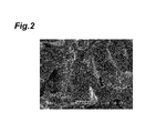
- Fig. 2 illustrates a photograph of a fracture surface of the magnetic body of Comparative Example 7 taken by the SEM. In contrast to Example 4, Comparative Example 7 grew grains of magnetic particles without exhibiting a fine organization structure such as that of Example 4.
- Fig. 4 illustrates the magnetization vs. magnetic field curve of Comparative Example 3.
- Fig. 5 illustrates the magnetization vs. magnetic field curve of Comparative Example 7.
- FIG. 6 to 8 illustrate the results of analysis of Example 3.
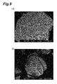
- FIGs. 9 to 11 illustrate the results of analysis of Comparative Example 5.
- Figs. 6a and 6b are backscattered electron images of a cross section of the magnetic body of Example 3.
- Regions 7 and 8 in Figs. 6a and 6b are positions (measurement regions) where data for element mapping were collected by the EPMA analysis.
- the region 7 has a size of 20 ⁇ 20 ⁇ m.
- the region 8 has a size of 51.2 ⁇ 51.2 ⁇ m.
- Fig. 7 is an element distribution map within the region 7 according to the EPMA analysis.
- Fig. 8 is an element distribution map within the region 8 according to the EPMA analysis.
- Figs. 9a and 9b are backscattered electron images of a part of a cross section of the magnetic body of Comparative Example 5.
- Regions 10 and 11 in Figs. 9a and 9b are positions (measurement regions) where data for element mapping were collected by the EPMA analysis.
- the region 10 has a size of 20 ⁇ 20 ⁇ m.
- the region 11 has a size of 51.2 ⁇ 51.2 ⁇ m.
- Fig. 10 is an element distribution map within the region 10 according to the EPMA analysis.
- Fig. 11 is an element distribution map within the region 11 according to the EPMA analysis.
- Example 3 According to the element distribution maps based on the EPMA analysis, Cu added in Example 3 was seen to be segregated without uniformly being dispersed in the magnetic body.
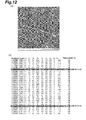
- FIG. 12(a) and 12(b) illustrate the results of Example 3.
- Figs. 13(a) and 13(b) illustrate the results of Comparative Example 5.
- LG20000 to LG20029 in Fig. 12(b) are locations (analysis locations) where contents of elements were measured by the STEM-EDS and correspond to points arranged at substantially equally-spaced intervals on a line segment LG2 in Fig. 12(a) .
- FIG. 13(b) are locations (analysis locations) where contents of elements were measured by the STEM-EDS and correspond to points arranged at substantially equally-spaced intervals on a line segment LG5 in Fig. 13(a) .
- the element contents at each of the analysis locations illustrated in Figs. 12(b) and 13(b) are expressed in the unit of atom %.
- the arrows in Figs. 12(a) and 13(a) indicate respective directions in which the line analysis was performed.
- LG20000 in Fig. 12(b) is the start point of the line analysis and located on the origin side of the arrow in Fig. 12(a) .
- LG20029 in Fig. 12(b) is the end point of the line analysis and located on the leading end side of the arrow in Fig.
- LG50000 in Fig. 13(b) is the start point of the line analysis and located on the origin side of the arrow in Fig. 13(a) .
- LG50029 in Fig. 13(b) is the end point of the line analysis and located on the leading end side of the arrow in Fig. 13(a) .
- the lengths (unit: ⁇ m) attached to LG20000 to LG20029 in Fig. 12(b) are respective distances from LG20000 to the analysis locations.
- the lengths (unit: ⁇ m) attached to LG50000 to LG50029 in Fig. 13(b) are respective distances from LG50000 to the analysis locations.
- FIG. 14(a), 14(b), and 14(c) illustrate the results of analysis of Example 3.
- Figs. 15(a), 15(b), and 15(c) illustrate the results of analysis of Comparative Example 5.
- Contents of elements at each of measurement locations "+” illustrated in Figs. 14(a) and 14(b) were measured by the STEM-EDS.
- Fig. 14(c) lists the element contents at each of the measurement locations in Figs. 14(a) and 14(b) .
- Contents of elements at each of measurement locations "+” illustrated in Figs. 15(a) and 15(b) were measured by the STEM-EDS.
- FIG. 15(c) lists the element contents at each of the measurement locations in Figs. 15(a) and 15(b) .
- grain boundary in Figs. 14(c) and 15(c) is meant a boundary region between two crystal particles (main-phase particles) constituting the magnetic body.
- grain boundary triple junction is meant a phase surrounded by three or more crystal particles constituting the magnetic body.
- Example 3 When Tables 3 and 4 were compared with each other, the Cu content in the main-phase particles was seen to be higher in Example 3 than in Comparative Example 5. In Example 3, Cu was seen to be segregated at the grain boundary triple junctions. As with Example 3 and Comparative Example 5, the other examples and comparative examples were subjected to the point analysis by the STEM-EDS. Table 5 lists the Cu contents in the main-phase particles of the examples and comparative examples determined from the results of point analysis.
- Table 6 shows the relationship between the residual magnetic flux density listed in Table 5 and the Cu amount and heat treatment temperature.
- Table 7 shows the relationship between the coercive force listed in Table 5 and the Cu amount and heat treatment temperature.
- Table 8 shows the relationship between the mf/HcJ listed in Table 5 and the Cu amount and heat treatment temperature.
- Table 9 shows the relationship between the Cu content in the main-phase particles listed in Table 5 and the Cu amount and heat treatment temperature. In Tables 6 to 9, the values marked with "*" are those of the examples.
- the low coercive force in Examples 1 to 6 is assumed to have resulted from the fact that the anisotropic magnetic field HA of Nd 2 Fe 14 B in the main-phase particles decreased.
- a Cu-rare-earth compound e.g., NdCu 5
- the present invention can reversibly change its magnetic force with a small external magnetic field while having a high residual magnetic flux density and thus is suitable as a variable-magnetic-force magnet for variable-magnetic-flux motors equipped in home appliances, hybrid cars, electric trains, elevators, and the like.
Landscapes
- Chemical & Material Sciences (AREA)
- Engineering & Computer Science (AREA)
- Mechanical Engineering (AREA)
- Materials Engineering (AREA)
- Metallurgy (AREA)
- Organic Chemistry (AREA)
- Power Engineering (AREA)
- Crystallography & Structural Chemistry (AREA)
- Inorganic Chemistry (AREA)
- Manufacturing & Machinery (AREA)
- Physics & Mathematics (AREA)
- Electromagnetism (AREA)
- Hard Magnetic Materials (AREA)
- Powder Metallurgy (AREA)
Applications Claiming Priority (2)
| Application Number | Priority Date | Filing Date | Title |
|---|---|---|---|
| JP2010290821 | 2010-12-27 | ||
| PCT/JP2011/079401 WO2012090765A1 (fr) | 2010-12-27 | 2011-12-19 | Corps magnétique |
Publications (2)
| Publication Number | Publication Date |
|---|---|
| EP2660829A1 true EP2660829A1 (fr) | 2013-11-06 |
| EP2660829A4 EP2660829A4 (fr) | 2017-11-29 |
Family
ID=46382876
Family Applications (1)
| Application Number | Title | Priority Date | Filing Date |
|---|---|---|---|
| EP11853050.0A Withdrawn EP2660829A4 (fr) | 2010-12-27 | 2011-12-19 | Corps magnétique |
Country Status (5)
| Country | Link |
|---|---|
| US (1) | US8981888B2 (fr) |
| EP (1) | EP2660829A4 (fr) |
| JP (1) | JP5527434B2 (fr) |
| CN (1) | CN103282976B (fr) |
| WO (1) | WO2012090765A1 (fr) |
Cited By (2)
| Publication number | Priority date | Publication date | Assignee | Title |
|---|---|---|---|---|
| EP2722856A1 (fr) * | 2012-10-17 | 2014-04-23 | Shin-Etsu Chemical Co., Ltd. | Aimant fritté de terres rares et procédé de fabrication |
| US9850559B2 (en) * | 2014-04-15 | 2017-12-26 | Tdk Corporation | Permanent magnet and variable magnetic flux motor |
Families Citing this family (13)
| Publication number | Priority date | Publication date | Assignee | Title |
|---|---|---|---|---|
| WO2014068655A1 (fr) * | 2012-10-30 | 2014-05-08 | 三菱電機株式会社 | Moteur électrique ayant un aimant permanent incorporé et équipement de réfrigération et de conditionnement d'air équipé de ce dernier |
| CN104674115A (zh) * | 2013-11-27 | 2015-06-03 | 厦门钨业股份有限公司 | 一种低b的稀土磁铁 |
| JP5686213B1 (ja) * | 2014-03-28 | 2015-03-18 | Tdk株式会社 | R−t−b系永久磁石 |
| JP5686212B1 (ja) * | 2014-03-28 | 2015-03-18 | Tdk株式会社 | R−t−b系永久磁石 |
| JP5686214B1 (ja) | 2014-03-28 | 2015-03-18 | Tdk株式会社 | R−t−b系永久磁石 |
| JP5729511B1 (ja) * | 2014-04-21 | 2015-06-03 | Tdk株式会社 | R−t−b系永久磁石、及び、回転機 |
| JP6645219B2 (ja) * | 2016-02-01 | 2020-02-14 | Tdk株式会社 | R−t−b系焼結磁石用合金、及びr−t−b系焼結磁石 |
| JP6635054B2 (ja) * | 2017-01-06 | 2020-01-22 | 株式会社村田製作所 | 抵抗素子およびその製造方法 |
| DE102018107429A1 (de) | 2017-03-31 | 2018-10-04 | Tdk Corporation | R-t-b basierter permanentmagnet |
| DE102018107491A1 (de) | 2017-03-31 | 2018-10-04 | Tdk Corporation | R-t-b basierter permanentmagnet |
| WO2019230457A1 (fr) | 2018-05-29 | 2019-12-05 | Tdk株式会社 | Aimant à base de r-t-b, moteur et générateur |
| CN110556223B (zh) * | 2019-09-30 | 2021-07-02 | 厦门钨业股份有限公司 | 一种钕铁硼磁体材料及其制备方法和应用 |
| CN114284018B (zh) * | 2021-12-27 | 2025-01-28 | 烟台正海磁性材料股份有限公司 | 钕铁硼磁体及其制备方法和应用 |
Family Cites Families (18)
| Publication number | Priority date | Publication date | Assignee | Title |
|---|---|---|---|---|
| JP2720040B2 (ja) * | 1988-02-26 | 1998-02-25 | 住友特殊金属株式会社 | 焼結永久磁石材料とその製造方法 |
| CA2023924A1 (fr) * | 1989-12-19 | 1991-06-20 | Earl G. Brewer | Additifs d'alliage a faible concentration pour aimants de nd-fe-b faconnee a chaud |
| JPH0475302A (ja) * | 1990-07-18 | 1992-03-10 | Tokin Corp | R・Fe・B系ボンド磁石の製造方法 |
| EP0782761B1 (fr) * | 1994-09-19 | 1998-08-12 | Siemens Aktiengesellschaft | Interrupteur de protection differentielle pourvu d'un materiau pour circuit magnetique special |
| CN1136588C (zh) * | 1995-10-16 | 2004-01-28 | 坩埚材料有限公司 | 稀土-Fe-B磁体及其改进方法 |
| JP3777225B2 (ja) * | 1996-08-19 | 2006-05-24 | 株式会社Neomax | 高磁束密度を有する等方性永久磁石粉末とその製造方法 |
| JPH1088295A (ja) * | 1996-09-19 | 1998-04-07 | Santoku Kinzoku Kogyo Kk | 希土類−鉄−ボロン系ボンド磁石用合金 |
| US7199690B2 (en) * | 2003-03-27 | 2007-04-03 | Tdk Corporation | R-T-B system rare earth permanent magnet |
| JP4415374B2 (ja) * | 2004-03-31 | 2010-02-17 | Tdk株式会社 | 希土類焼結磁石の製造方法 |
| JP4730546B2 (ja) * | 2006-04-14 | 2011-07-20 | 信越化学工業株式会社 | 希土類永久磁石の製造方法 |
| CN100454449C (zh) * | 2006-04-24 | 2009-01-21 | 严高林 | 退化稀土永磁材料再生高性能永磁体的方法 |
| JP4519118B2 (ja) * | 2006-10-25 | 2010-08-04 | 株式会社三徳 | ボンド磁石に用いる希土類−鉄−ボロン系コンポジット磁石用合金 |
| JP4924615B2 (ja) * | 2006-11-30 | 2012-04-25 | 日立金属株式会社 | R−Fe−B系微細結晶高密度磁石およびその製造方法 |
| JP2010034522A (ja) | 2008-06-23 | 2010-02-12 | Toshiba Corp | 永久磁石およびその製造方法、モータ用永久磁石および永久磁石モータ |
| JP4868182B2 (ja) * | 2008-11-10 | 2012-02-01 | 信越化学工業株式会社 | Sm−R−T−B(−M)系焼結磁石 |
| JP5262643B2 (ja) * | 2008-12-04 | 2013-08-14 | 信越化学工業株式会社 | Nd系焼結磁石及びその製造方法 |
| EP3150567B1 (fr) * | 2009-07-08 | 2025-11-19 | TDK Corporation | Matériau magnétique à base de ferrite |
| MY174972A (en) * | 2011-05-02 | 2020-05-29 | Shinetsu Chemical Co | Rare earth permanent magnets and their preparation |
-
2011
- 2011-12-19 EP EP11853050.0A patent/EP2660829A4/fr not_active Withdrawn
- 2011-12-19 JP JP2012550846A patent/JP5527434B2/ja active Active
- 2011-12-19 US US13/997,788 patent/US8981888B2/en active Active
- 2011-12-19 CN CN201180063123.4A patent/CN103282976B/zh active Active
- 2011-12-19 WO PCT/JP2011/079401 patent/WO2012090765A1/fr not_active Ceased
Non-Patent Citations (1)
| Title |
|---|
| See references of WO2012090765A1 * |
Cited By (3)
| Publication number | Priority date | Publication date | Assignee | Title |
|---|---|---|---|---|
| EP2722856A1 (fr) * | 2012-10-17 | 2014-04-23 | Shin-Etsu Chemical Co., Ltd. | Aimant fritté de terres rares et procédé de fabrication |
| EP3410446A1 (fr) * | 2012-10-17 | 2018-12-05 | Shin-Etsu Chemical Co., Ltd. | Aimant fritté anisotrope aux terres rares et procédé de fabrication |
| US9850559B2 (en) * | 2014-04-15 | 2017-12-26 | Tdk Corporation | Permanent magnet and variable magnetic flux motor |
Also Published As
| Publication number | Publication date |
|---|---|
| WO2012090765A1 (fr) | 2012-07-05 |
| JP5527434B2 (ja) | 2014-06-18 |
| JPWO2012090765A1 (ja) | 2014-06-05 |
| US20130271249A1 (en) | 2013-10-17 |
| CN103282976A (zh) | 2013-09-04 |
| US8981888B2 (en) | 2015-03-17 |
| CN103282976B (zh) | 2017-02-08 |
| EP2660829A4 (fr) | 2017-11-29 |
Similar Documents
| Publication | Publication Date | Title |
|---|---|---|
| US8981888B2 (en) | Magnetic body | |
| US9997284B2 (en) | Sintered magnet | |
| JP7379362B2 (ja) | 低B含有R-Fe-B系焼結磁石及び製造方法 | |
| EP3075874B1 (fr) | Aimant de terres rares à faible teneur en b | |
| KR101702696B1 (ko) | 자석용 분말 | |
| KR101475641B1 (ko) | 희토류-철-질소계 합금재, 희토류-철-질소계 합금재의 제조 방법, 희토류-철계 합금재, 및 희토류-철계 합금재의 제조 방법 | |
| JP7180095B2 (ja) | R‐t‐b系焼結磁石 | |
| US20150132174A1 (en) | Rare Earth Composite Magnets with Increased Resistivity | |
| EP2779179B1 (fr) | Particules d'aimant aux terres rares à base R-T-B, procédé de production de particules d'aimant aux terres rares à base R-T-B et aimant lié | |
| EP2500915B1 (fr) | Aimant R-T-B fritté de terres rares | |
| JP6848735B2 (ja) | R−t−b系希土類永久磁石 | |
| EP3121821B1 (fr) | Aimant permanent, moteur et générateur | |
| JP4371188B2 (ja) | 高比電気抵抗性希土類磁石及びその製造方法 | |
| US10886062B2 (en) | Method for preparing rare-earth permanent magnet | |
| WO2011070847A1 (fr) | Poudre d'aimant anisotrope de terre rare, procédé de production associé et aimant collé | |
| US10256016B2 (en) | Rare earth based magnet | |
| JP2741508B2 (ja) | 磁気異方性焼結磁石とその製造方法 | |
| JP2853838B2 (ja) | 希土類永久磁石の製造方法 | |
| JPH06207204A (ja) | 希土類永久磁石の製造方法 | |
| JP3652751B2 (ja) | 異方性ボンド磁石 | |
| JP2581179B2 (ja) | 耐食性に優れた希土類−B−Fe系焼結磁石の製造法 | |
| KR102254190B1 (ko) | 자기 이방성 희토류 영구자석 제조방법 및 이를 통해 제조된 자기 이방성 희토류 영구자석 | |
| JPH0521219A (ja) | 希土類永久磁石の製造方法 | |
| JPH02298232A (ja) | 耐食性および磁気特性に優れた希土類―B―Fe系焼結磁石の製造方法 | |
| JP3703903B2 (ja) | 異方性ボンド磁石 |
Legal Events
| Date | Code | Title | Description |
|---|---|---|---|
| PUAI | Public reference made under article 153(3) epc to a published international application that has entered the european phase |
Free format text: ORIGINAL CODE: 0009012 |
|
| 17P | Request for examination filed |
Effective date: 20130604 |
|
| AK | Designated contracting states |
Kind code of ref document: A1 Designated state(s): AL AT BE BG CH CY CZ DE DK EE ES FI FR GB GR HR HU IE IS IT LI LT LU LV MC MK MT NL NO PL PT RO RS SE SI SK SM TR |
|
| DAX | Request for extension of the european patent (deleted) | ||
| RA4 | Supplementary search report drawn up and despatched (corrected) |
Effective date: 20171026 |
|
| RIC1 | Information provided on ipc code assigned before grant |
Ipc: C22C 38/12 20060101ALI20171020BHEP Ipc: C22C 38/10 20060101ALI20171020BHEP Ipc: B22F 3/10 20060101ALI20171020BHEP Ipc: H01F 1/057 20060101ALI20171020BHEP Ipc: H01F 1/08 20060101ALI20171020BHEP Ipc: H01F 7/02 20060101ALI20171020BHEP Ipc: H01F 1/053 20060101AFI20171020BHEP Ipc: C22C 38/00 20060101ALI20171020BHEP Ipc: C22C 33/02 20060101ALI20171020BHEP Ipc: C22C 38/16 20060101ALI20171020BHEP Ipc: B22F 9/02 20060101ALI20171020BHEP Ipc: C22C 38/06 20060101ALI20171020BHEP Ipc: C22C 1/02 20060101ALI20171020BHEP |
|
| GRAP | Despatch of communication of intention to grant a patent |
Free format text: ORIGINAL CODE: EPIDOSNIGR1 |
|
| INTG | Intention to grant announced |
Effective date: 20190426 |
|
| STAA | Information on the status of an ep patent application or granted ep patent |
Free format text: STATUS: THE APPLICATION IS DEEMED TO BE WITHDRAWN |
|
| 18D | Application deemed to be withdrawn |
Effective date: 20190907 |