EP2663406B1 - Dispositif de revêtement a chaud d'une surface - Google Patents
Dispositif de revêtement a chaud d'une surface Download PDFInfo
- Publication number
- EP2663406B1 EP2663406B1 EP12701688.9A EP12701688A EP2663406B1 EP 2663406 B1 EP2663406 B1 EP 2663406B1 EP 12701688 A EP12701688 A EP 12701688A EP 2663406 B1 EP2663406 B1 EP 2663406B1
- Authority
- EP
- European Patent Office
- Prior art keywords
- wire
- adjustment
- guide tube
- coating
- piece
- Prior art date
- Legal status (The legal status is an assumption and is not a legal conclusion. Google has not performed a legal analysis and makes no representation as to the accuracy of the status listed.)
- Active
Links
Images


Classifications
-
- B—PERFORMING OPERATIONS; TRANSPORTING
- B05—SPRAYING OR ATOMISING IN GENERAL; APPLYING FLUENT MATERIALS TO SURFACES, IN GENERAL
- B05B—SPRAYING APPARATUS; ATOMISING APPARATUS; NOZZLES
- B05B7/00—Spraying apparatus for discharge of liquids or other fluent materials from two or more sources, e.g. of liquid and air, of powder and gas
- B05B7/16—Spraying apparatus for discharge of liquids or other fluent materials from two or more sources, e.g. of liquid and air, of powder and gas incorporating means for heating or cooling the material to be sprayed
- B05B7/18—Spraying apparatus for discharge of liquids or other fluent materials from two or more sources, e.g. of liquid and air, of powder and gas incorporating means for heating or cooling the material to be sprayed the material having originally the shape of a wire, rod or the like
-
- B—PERFORMING OPERATIONS; TRANSPORTING
- B05—SPRAYING OR ATOMISING IN GENERAL; APPLYING FLUENT MATERIALS TO SURFACES, IN GENERAL
- B05B—SPRAYING APPARATUS; ATOMISING APPARATUS; NOZZLES
- B05B7/00—Spraying apparatus for discharge of liquids or other fluent materials from two or more sources, e.g. of liquid and air, of powder and gas
- B05B7/16—Spraying apparatus for discharge of liquids or other fluent materials from two or more sources, e.g. of liquid and air, of powder and gas incorporating means for heating or cooling the material to be sprayed
- B05B7/22—Spraying apparatus for discharge of liquids or other fluent materials from two or more sources, e.g. of liquid and air, of powder and gas incorporating means for heating or cooling the material to be sprayed electrically, magnetically or electromagnetically, e.g. by arc
- B05B7/222—Spraying apparatus for discharge of liquids or other fluent materials from two or more sources, e.g. of liquid and air, of powder and gas incorporating means for heating or cooling the material to be sprayed electrically, magnetically or electromagnetically, e.g. by arc using an arc
- B05B7/224—Spraying apparatus for discharge of liquids or other fluent materials from two or more sources, e.g. of liquid and air, of powder and gas incorporating means for heating or cooling the material to be sprayed electrically, magnetically or electromagnetically, e.g. by arc using an arc the material having originally the shape of a wire, rod or the like
-
- C—CHEMISTRY; METALLURGY
- C23—COATING METALLIC MATERIAL; COATING MATERIAL WITH METALLIC MATERIAL; CHEMICAL SURFACE TREATMENT; DIFFUSION TREATMENT OF METALLIC MATERIAL; COATING BY VACUUM EVAPORATION, BY SPUTTERING, BY ION IMPLANTATION OR BY CHEMICAL VAPOUR DEPOSITION, IN GENERAL; INHIBITING CORROSION OF METALLIC MATERIAL OR INCRUSTATION IN GENERAL
- C23C—COATING METALLIC MATERIAL; COATING MATERIAL WITH METALLIC MATERIAL; SURFACE TREATMENT OF METALLIC MATERIAL BY DIFFUSION INTO THE SURFACE, BY CHEMICAL CONVERSION OR SUBSTITUTION; COATING BY VACUUM EVAPORATION, BY SPUTTERING, BY ION IMPLANTATION OR BY CHEMICAL VAPOUR DEPOSITION, IN GENERAL
- C23C4/00—Coating by spraying the coating material in the molten state, e.g. by flame, plasma or electric discharge
- C23C4/12—Coating by spraying the coating material in the molten state, e.g. by flame, plasma or electric discharge characterised by the method of spraying
- C23C4/131—Wire arc spraying
-
- C—CHEMISTRY; METALLURGY
- C23—COATING METALLIC MATERIAL; COATING MATERIAL WITH METALLIC MATERIAL; CHEMICAL SURFACE TREATMENT; DIFFUSION TREATMENT OF METALLIC MATERIAL; COATING BY VACUUM EVAPORATION, BY SPUTTERING, BY ION IMPLANTATION OR BY CHEMICAL VAPOUR DEPOSITION, IN GENERAL; INHIBITING CORROSION OF METALLIC MATERIAL OR INCRUSTATION IN GENERAL
- C23C—COATING METALLIC MATERIAL; COATING MATERIAL WITH METALLIC MATERIAL; SURFACE TREATMENT OF METALLIC MATERIAL BY DIFFUSION INTO THE SURFACE, BY CHEMICAL CONVERSION OR SUBSTITUTION; COATING BY VACUUM EVAPORATION, BY SPUTTERING, BY ION IMPLANTATION OR BY CHEMICAL VAPOUR DEPOSITION, IN GENERAL
- C23C4/00—Coating by spraying the coating material in the molten state, e.g. by flame, plasma or electric discharge
- C23C4/12—Coating by spraying the coating material in the molten state, e.g. by flame, plasma or electric discharge characterised by the method of spraying
- C23C4/134—Plasma spraying
-
- H—ELECTRICITY
- H05—ELECTRIC TECHNIQUES NOT OTHERWISE PROVIDED FOR
- H05H—PLASMA TECHNIQUE; PRODUCTION OF ACCELERATED ELECTRICALLY-CHARGED PARTICLES OR OF NEUTRONS; PRODUCTION OR ACCELERATION OF NEUTRAL MOLECULAR OR ATOMIC BEAMS
- H05H1/00—Generating plasma; Handling plasma
- H05H1/24—Generating plasma
- H05H1/48—Generating plasma using an arc
-
- B—PERFORMING OPERATIONS; TRANSPORTING
- B05—SPRAYING OR ATOMISING IN GENERAL; APPLYING FLUENT MATERIALS TO SURFACES, IN GENERAL
- B05B—SPRAYING APPARATUS; ATOMISING APPARATUS; NOZZLES
- B05B13/00—Machines or plants for applying liquids or other fluent materials to surfaces of objects or other work by spraying, not covered by groups B05B1/00 - B05B11/00
- B05B13/06—Machines or plants for applying liquids or other fluent materials to surfaces of objects or other work by spraying, not covered by groups B05B1/00 - B05B11/00 specially designed for treating the inside of hollow bodies
- B05B13/0627—Arrangements of nozzles or spray heads specially adapted for treating the inside of hollow bodies
- B05B13/0636—Arrangements of nozzles or spray heads specially adapted for treating the inside of hollow bodies by means of rotatable spray heads or nozzles
Definitions
- the invention relates to a device for thermal coating of a surface according to the preamble of claim 1 and to a method carried out thereby and a component produced by the method.
- All apparatus include: a wire feeder for feeding a wire, the wire acting as a first electrode; a source of plasma gas for generating a plasma gas stream; a nozzle body having a nozzle opening through which the plasma gas stream is passed as a plasma jet to a wire end; and a second electrode disposed in the plasma gas stream before entering the nozzle orifice.
- This arc also forms the plasma gas flowing through the nozzle opening.
- the plasma jet emerging from the nozzle opening impinges on the end of the wire and there causes a melting of the wire with the arc and the removal of the molten wire material in the direction of the surface to be coated.
- Secondary air nozzles are mounted annularly around the nozzle opening, creating a fluidized secondary gas jet which strikes the wire-end-melted material behind the wire end to accelerate transport toward the surface to be coated and secondary atomization of the molten wire material.
- the coating should be produced without major inclusions of non or only partially melted spray particles. Such inclusions or so-called scratches are usually caused by not completely molten wire material. It has been found that if the wire is to be melted as completely and uniformly as possible, exact positioning of the wire relative to the nozzle opening is necessary. Likewise, a very short operating time of the device in the coating operation can make a new adjustment of the wire position necessary.
- the object of the invention is therefore to provide an improved device with which a safe and good coating of the surface, in particular a coating without inclusions and splashes, can be produced in a simple manner.
- the wire feeder is adjustable, whereby the wire end located in front of the nozzle opening can be moved by a certain displacement, an adjustment of the wire or the wire end can be made relative to the nozzle opening in a simple manner. Under the adjustability or adjustment of the wire is a very small adjustment to understand.
- adjustment paths of less than 0.2 mm are usually necessary in order to achieve sufficient accurate positioning.
- the adjustment is not greater than 0.08 mm.
- the wire feeder can, of course, due to the design, also move the wire end to larger adjustment paths. However, this is not necessary for the exact position of the wire end, but at best to be able to determine the optimal position during the adjustment process by a larger adjustment is driven and then the optimal wire position is determined iteratively.
- an adjustment direction of the adjustment path is at least partially transverse to the wire longitudinal axis and / or at least partially transverse to the plasma jet.
- the wire feed direction can be designed so that an adjustment takes place in any direction.
- At least one component of the adjustment is transverse to the wire axis.
- Another component of the adjustment is transverse to the plasma jet.
- the adjustment of the wire end results in any case in a lateral displacement relative to the plasma jet.
- the nozzle longitudinal axis of the nozzle opening approximately in the same direction as the plasma jet.
- the wire feeder is adjustable by means of static adjustment.
- Static means that the setting is not changed during one or more coating operations.
- the setting is made when the device is switched off.
- the wire can be positioned in a simple manner in front of the nozzle opening or in the plasma jet.
- Particularly suitable are adjusting screws, by means of which the exact position of the wire can be adjusted quite accurately.
- the wire feed device is adjustable by means of dynamic adjustment means. This also allows an adjustment during operation of the device, including during a coating process.
- the adjustment can be quasi-static, so there is a continuous, but slight adjustment instead of the wire is always in the correct position.
- the frequency may be adjusted to the speed of the device to compensate for a slight curvature of the rotating relative to the device wire.
- the frequency can also be higher than the speed.
- the frequency is such that a slight swinging of the wire end in the higher frequency range, eg. B. between 1 kHz and 10 kHz, to ensure a safe melting of the wire end by the wire end is deflected evenly within certain positioning limits. This ensures that all areas of the wire end are at least temporarily in the optimum position to the plasma jet. Due to the high-frequency vibration, individual areas of the wire end only leave this optimum position so short that no dangerous splashes or inclusions can form during melting. Before these form, the wire end is already swung back and a previously lying outside area is again in optimal position. This significantly improves the melting behavior of the wire end.
- the higher frequency range eg. B. between 1 kHz and 10 kHz
- Piezo crystals which are reliable and fast with little power, i. E. high frequency, can be switched.
- piezo stacks In order to achieve the required adjustment paths are possibly so-called piezo stacks, so to use several stacked piezocrystals.
- the wire feed device has an adjustable guide piece on which the adjusting means act.
- An adjustment of the guide piece allows the exact alignment of the wire.
- This guide piece is usefully arranged just before the exit of the wire from the Drahtzu Swiss thesis.
- the wire feed device has an adjustable guide tube.
- the wire feed device preferably has a stationary attachment piece, wherein the guide tube connects the attachment piece and the guide piece.
- the wire feeding device can be fixed in the device, and by means of the guide tube, the wire is guided to the guide piece.
- This provides a relatively long guide of the wire before it exits the leader.
- guide tube, attachment piece and guide piece on a continuous bore, through which the wire is guided.
- the leadership of the Wire in the wire feeder can also be done by other suitable means.
- the attachment piece and guide tube are made in one piece and the guide tube is elastically deformed during adjustment. Due to the small adjustment paths, the elastic deformation of the guide tube may be sufficient to position the wire.
- the guide piece can be firmly connected to the guide tube here. Or the guide piece is a separate part, the guide tube then takes over only the supply of the wire to the guide piece. The separate guide tube and guide piece can be centered over the wire itself.
- Advantageously fastening piece and guide tube are made in two parts and between the attachment piece and guide tube, an elastic element is arranged, in particular an O-ring. While the attachment piece is firmly anchored in the device, the guide tube can be supported by the elastic element. At the same time allows the elastic support a small deflection of the guide tube to accomplish the adjustment of the wire end.
- the guide piece may be firmly connected to the guide tube or be designed as a separate part. Again, the wire takes over the centering of the individual parts to each other, at least of attachment piece and guide tube, and if the guide piece is also separate, of guide piece and guide tube.
- the guide piece has lateral guide surfaces for guiding in the device transversely to the adjustment direction. Since the adjustment direction is essentially transverse to the plasma jet, the positioning in the direction of the plasma jet is sufficient by means of the guide surfaces.
- the dynamic / and or static adjustment during the starting process of the method may be different than during the actual coating process.
- the wire position or the Dynamic adjusting movement can be well adapted to the requirements of an optimal wire melt. This includes z. B. that at the start of the process, a position of the wire is different than during coating, and that when starting the process, a dynamic adjustment is different than during coating, both with respect to the adjustment and the frequency of the adjustment.
- the small, adjustable wire feeder can be easily accommodated in a dimensionally limited device. Limited because a device that is to be able to enter a cylinder bore can only have a certain dimensions, usually not more than 4 to 5 cm in diameter.
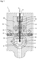
- FIGS. 1 and 2 show sections through an inventive device 1.
- the device 1 has a nozzle body 2 with a nozzle opening 3 and a wire feed device 4 for supplying a wire 5. It shows Fig. 1 the longitudinal section along the wire 5 and transversely to the nozzle opening 3 and FIG. 2 the longitudinal section along the wire 5 and along the nozzle opening 3.
- the wire 5 is connected via an electrical contact, not shown, above the Wire feeder 4 is arranged, connected to a power source and thus acts as a first electrode.
- a plasma gas feed 6 designed as a cavity, which is connected to a source of plasma gas (not shown).
- a second electrode 7 is arranged, which is also connected to the power source.
- gas flows from the plasma gas supply 6 through the nozzle opening 3 onto the wire end 8 of the wire 5.
- the current source supplies a corresponding voltage and current, an arc forms between the wire end 8 and the second electrode 7 through the nozzle opening 5 , whereby the gas flowing through the nozzle opening 5 ionizes and thus becomes the plasma gas.
- the plasma jet emerging from the nozzle opening 3 impinges on the wire end 8 and causes there with the arc a melting of the wire 5 and the removal of the molten wire material in the direction of the surface to be coated. In operation, therefore, the wire 5 must be constantly promoted in the direction of feed V to compensate for the melting of the wire end 8.
- Secondary air nozzles 9 are mounted in annular fashion around the nozzle opening 3 and produce a fluidized secondary gas jet which atomises the molten material at the wire end 8 towards the melt area, thus accelerating transport towards the surface to be coated and finer distribution of the molten wire material ,
- the wire feeder 4 In the FIGS. 3 and 4 only the wire feeder 4 is shown. It consists of an adjustable guide piece 11, an adjustable guide tube 12 and a fastened in the device 1 attachment piece 13, wherein the guide tube 12 attachment piece 13 and guide piece 11 connects.
- This guide of the wire 5 in turn centers the three parts against each other.
- the guide piece 11 has lateral guide surfaces 14 for guiding in the device 1 transversely to the adjustment directions F.
- the guide piece 11 On the underside, the guide piece 11 on lower support surfaces 15, which cause a guide of the guide piece 11 in the direction of the wire longitudinal axis.
- the adjustment S is shown by the dashed line of the guide piece 1 to the left and right. At least at its lower end, the guide tube 12 moves accordingly, while it is rather immovable in the upper region, at the transition to the attachment piece 13.
- an O-ring 16 is arranged between attachment piece 13 and guide tube 12, an O-ring 16 is arranged. Via an external thread, the attachment piece 13 is firmly screwed in the device 1 and presses the O-ring 16 against the guide tube 12, which in turn presses the guide piece 11 via the support surfaces 15 against the device 1.
- guide piece 11, guide tube 12 and attachment piece 13th braced against each other and clearly positioned in the device - except for the degree of freedom of the adjustment directions F - wherein the tension depends on the degree of deformation of the O-ring 16.
- the bias of the O-ring 16 still has the task of allowing the adjustment of the guide piece 11, a rotation of the guide tube 12 relative to the attachment piece 13 by its elastic deformation.
- two grub screws 17 in the housing 18 of the device 1 are mounted. Via two insulating pieces 19, the grub screws 17 transmit the adjusting movement to the guide piece 11 and thus also hold the guide piece 11 in the correct position.
- the displacement S is not greater than 0.2 mm, usually even less than 0.08 mm. Therefore, the use of relatively small grub screws 17 is provided with fine thread, so low slope.
- size M3 set screws with a pitch of 0.5 mm are used.
- the wire feeder 4 is connected to the wire 5 as the first electrode.
- the housing 18 of the device 1 is electrically connected to the second electrode 7.
- the insulation of the wire feeder 4 relative to the housing 18 is carried out by the wire feeder 4 is fixed in the insulating block 20, wherein the insulating block 20 is made of a non-conductive plastic.
- the insulating pieces 19 are therefore necessary so that via the grub screws 17 no electrical contact between the housing 18 and wire feed 4 is made.
- the insulating pieces 19 may also be designed as piezoelectric actuators. Then either a static voltage and thus a static adjustment can be applied to create a low clearance compensation. Or an AC voltage can be applied which causes a dynamic adjustment of the position of the wire 5.
- the dynamic adjustment takes place with a frequency not less than 50 Hz. Particularly advantageous is an adjustment frequency of 1 kHz or greater. In any event, these frequencies are significantly higher than the speed of the device 1 as it rotates about the fixed wire 5 to produce the coating in a bore.
- the speed of the device 1 is usually a function of the bore diameter to be coated in a range of 100 - 700 U / min, ie at a frequency of 1 - 12 Hz.
- adjustment frequency is significantly higher and the fixed wire 5 to which the Device turns 1, is applied from all sides with the necessary adjustment of the plasma jet.
- the dynamic adjustment can also be combined with a static adjustment. Furthermore, during the starting process of the method, the dynamic / and or static adjustment may be different than during the actual coating process. This can be a variety of tolerances at the beginning and / or during the coating compensate.
Landscapes
- Engineering & Computer Science (AREA)
- Physics & Mathematics (AREA)
- Plasma & Fusion (AREA)
- Chemical & Material Sciences (AREA)
- Organic Chemistry (AREA)
- Chemical Kinetics & Catalysis (AREA)
- Materials Engineering (AREA)
- Mechanical Engineering (AREA)
- Metallurgy (AREA)
- Spectroscopy & Molecular Physics (AREA)
- Electromagnetism (AREA)
- Nozzles (AREA)
- Plasma Technology (AREA)
- Coating By Spraying Or Casting (AREA)
Claims (13)
- Dispositif pour le revêtement thermique d'une surface, comportant :un dispositif d'alimentation en fil (4), pour délivrer un fil (5), dans lequel le fil (5) agit comme une première électrode,une source de gaz de plasma destinée à générer un flux de gaz de plasma,une tête de pulvérisation (2) comportant une couverture de pulvérisation (3) à travers laquelle le flux de gaz de plasma est guidé sous la forme d'un jet de gaz de plasma sur une extrémité (8) du fil, etune deuxième électrode (7), qui est disposée dans le flux de gaz de plasma avant que celui-ci ne pénètre dans l'ouverture de pulvérisation (3), dans lequel le dispositif d'alimentation en fil (4) est réglable,caractérisé par un moyen de réglage à l'aide duquel l'extrémité (8) du fil se trouvant devant l'ouverture de pulvérisation (3) peut être déplacée dans une direction de réglage (F) sur un trajet de réglage déterminé au moins partiellement transversalement à l'axe longitudinal du fil et/ou au moins partiellement transversalement au jet de gaz de plasma, dans lequel le dispositif d'alimentation en fil (4) comporte au moins à son extrémité inférieure un tube de guidage (12) se déplaçant en association avec une pièce de guidage (11) réglable sous l'effet des moyens de réglage.
- Dispositif selon la revendication 1, caractérisé en ce que le dispositif d'alimentation en fil (4) est réglable à l'aide de moyens de réglage statiques, notamment au moyen de vis de réglage (17).
- Dispositif selon la revendication 1 ou 2, caractérisé en ce que le dispositif d'alimentation en fil est réglable à l'aide de moyens de réglage dynamiques, notamment au moyen d'actionneurs tels que des actionneurs piézoélectriques.
- Dispositif selon la revendication 1, caractérisé en ce que le dispositif d'alimentation en fil (4) comporte une pièce de fixation (13) fixe, dans lequel le tube de guidage (12) relie la pièce de fixation (13) à la pièce de guidage (11).
- Dispositif selon la revendication 4, caractérisé en ce que la pièce de fixation (13) et le tube de guidage (12) sont réalisés de manière solidaire et en ce que le tube de guidage (12) est déformé élastiquement lors du réglage.
- Dispositif selon la revendication 4, caractérisé en ce que la pièce de fixation (13) et le tube de guidage (12) sont réalisés en deux parties et en ce qu'un élément élastique (16), notamment un joint taurique, est disposé entre la pièce de fixation (13) et le tube de guidage (12).
- Dispositif selon la revendication 1, caractérisé en ce que la pièce de guidage (11) présente des surfaces de guidage latérales (14) destinées à être guidées dans le dispositif (1) transversalement à la direction de réglage (F).
- Procédé pour le revêtement thermique d'une surface au moyen d'un dispositif (1) selon l'une quelconque des revendications précédentes.
- Procédé selon la revendication 8,
caractérisé en ce que le trajet de réglage (S) du dispositif d'alimentation en fil (4) n'est pas supérieur à 0,2 mm, et plus particulièrement, n'est pas supérieur à 0,08 mm. - Procédé selon la revendication 8 ou 9, caractérisé en ce qu'un réglage dynamique est effectué à une fréquence non inférieure à 50 Hz, notamment non inférieure à 1 kHz.
- Procédé selon l'une quelconque des revendications 8 à 10,
caractérisé en ce que, pendant le processus de démarrage du procédé, un réglage dynamique et/ou statique est différent de celui qui est réalisé pendant le processus de revêtement proprement dit. - Revêtement, réalisé au moyen d'un procédé selon l'une quelconque des revendications 8 à 11.
- Revêtement selon la revendication 12, dans lequel le revêtement est un revêtement d'une surface de glissement de cylindre d'un moteur à combustion interne.
Applications Claiming Priority (2)
| Application Number | Priority Date | Filing Date | Title |
|---|---|---|---|
| DE102011002501A DE102011002501A1 (de) | 2011-01-11 | 2011-01-11 | Vorrichtung zum thermischen Beschichten einer Oberfläche |
| PCT/EP2012/050192 WO2012095371A1 (fr) | 2011-01-11 | 2012-01-06 | Dispositif pour le revêtement thermique d'une surface |
Publications (2)
| Publication Number | Publication Date |
|---|---|
| EP2663406A1 EP2663406A1 (fr) | 2013-11-20 |
| EP2663406B1 true EP2663406B1 (fr) | 2016-04-13 |
Family
ID=45558023
Family Applications (1)
| Application Number | Title | Priority Date | Filing Date |
|---|---|---|---|
| EP12701688.9A Active EP2663406B1 (fr) | 2011-01-11 | 2012-01-06 | Dispositif de revêtement a chaud d'une surface |
Country Status (5)
| Country | Link |
|---|---|
| US (1) | US9056326B2 (fr) |
| EP (1) | EP2663406B1 (fr) |
| CN (1) | CN103379965B (fr) |
| DE (1) | DE102011002501A1 (fr) |
| WO (1) | WO2012095371A1 (fr) |
Families Citing this family (10)
| Publication number | Priority date | Publication date | Assignee | Title |
|---|---|---|---|---|
| DE102013226361B4 (de) | 2013-01-04 | 2018-05-09 | Ford-Werke Gmbh | Vorrichtung zum thermischen Beschichten einer Oberfläche |
| DE102013200054A1 (de) | 2013-01-04 | 2014-07-10 | Ford-Werke Gmbh | Verfahren zum thermischen Beschichten einer Oberfläche |
| DE102013200062A1 (de) | 2013-01-04 | 2014-07-10 | Ford-Werke Gmbh | Vorrichtung zum thermischen Beschichten einer Oberfläche |
| DE102013200067A1 (de) | 2013-01-04 | 2014-07-10 | Ford-Werke Gmbh | Vorrichtung zum thermischen Beschichten einer Oberfläche |
| DE102013226690A1 (de) | 2013-01-04 | 2014-07-10 | Ford-Werke Gmbh | Vorrichtung zum thermischen Beschichten einer Oberfläche |
| EP3207167A2 (fr) | 2014-10-17 | 2017-08-23 | KS Kolbenschmidt GmbH | Revêtement pour composants de moteurs à combustion interne |
| CN104762585B (zh) * | 2015-03-25 | 2018-01-05 | 西安交通大学 | 一种利用金属丝导引熔融金属涂覆的成形装置及方法 |
| DE102016112098A1 (de) | 2016-07-01 | 2018-01-04 | Ks Huayu Alutech Gmbh | Vorrichtung zum thermischen Beschichten einer Oberfläche sowie Verfahren zur Messung der Lage oder der Form eines Drahtendes in einer Vorrichtung zum thermischen Beschichten einer Oberfläche |
| DE102017124303A1 (de) * | 2017-10-18 | 2019-04-18 | Grob-Werke Gmbh & Co. Kg | Verfahren und Vorrichtung zur Montage einer Drahtführung an einem Brennerkopf für eine Beschichtungsanlage |
| WO2020104438A1 (fr) | 2018-11-20 | 2020-05-28 | Ks Kolbenschmidt Gmbh | Composition de matière pour un revêtement destiné à des pièces de moteurs à combustion interne |
Family Cites Families (12)
| Publication number | Priority date | Publication date | Assignee | Title |
|---|---|---|---|---|
| DE851708C (de) | 1951-07-03 | 1956-07-26 | Friedhelm Dr-Ing Steyer | Elektro-Metallspritzpistole |
| US5109150A (en) * | 1987-03-24 | 1992-04-28 | The United States Of America As Represented By The Secretary Of The Navy | Open-arc plasma wire spray method and apparatus |
| GB2227027A (en) * | 1989-01-14 | 1990-07-18 | Ford Motor Co | Plasma arc spraying of metal onto a surface |
| DE4030541C2 (de) * | 1990-09-27 | 1997-10-02 | Dilthey Ulrich Prof Dr Ing | Brenner zur Beschichtung von Grundwerkstoffen mit pulverförmigen Zusatzwerkstoffen |
| US5707693A (en) * | 1996-09-19 | 1998-01-13 | Ingersoll-Rand Company | Method and apparatus for thermal spraying cylindrical bores |
| US5808270A (en) * | 1997-02-14 | 1998-09-15 | Ford Global Technologies, Inc. | Plasma transferred wire arc thermal spray apparatus and method |
| DE19856307C1 (de) * | 1998-12-07 | 2000-01-13 | Bosch Gmbh Robert | Vorrichtung zur Erzeugung eines freien kalten Plasmastrahles |
| US6372298B1 (en) | 2000-07-21 | 2002-04-16 | Ford Global Technologies, Inc. | High deposition rate thermal spray using plasma transferred wire arc |
| US6610959B2 (en) | 2001-04-26 | 2003-08-26 | Regents Of The University Of Minnesota | Single-wire arc spray apparatus and methods of using same |
| US6706993B1 (en) | 2002-12-19 | 2004-03-16 | Ford Motor Company | Small bore PTWA thermal spraygun |
| EP2236211B1 (fr) | 2009-03-31 | 2015-09-09 | Ford-Werke GmbH | Système pour la déposition thermique de revêtements par pulvérisation à arc électrique |
| WO2012088421A1 (fr) * | 2010-12-22 | 2012-06-28 | Flame-Spray Industries, Inc. | Procédé et appareil améliorés de projection thermique qui utilisent un arc fil transféré au plasma |
-
2011
- 2011-01-11 DE DE102011002501A patent/DE102011002501A1/de not_active Ceased
-
2012
- 2012-01-06 WO PCT/EP2012/050192 patent/WO2012095371A1/fr not_active Ceased
- 2012-01-06 EP EP12701688.9A patent/EP2663406B1/fr active Active
- 2012-01-06 CN CN201280004725.7A patent/CN103379965B/zh active Active
- 2012-01-06 US US13/978,856 patent/US9056326B2/en active Active
Also Published As
| Publication number | Publication date |
|---|---|
| CN103379965B (zh) | 2016-08-10 |
| DE102011002501A1 (de) | 2012-07-12 |
| EP2663406A1 (fr) | 2013-11-20 |
| US9056326B2 (en) | 2015-06-16 |
| CN103379965A (zh) | 2013-10-30 |
| WO2012095371A1 (fr) | 2012-07-19 |
| US20140014003A1 (en) | 2014-01-16 |
Similar Documents
| Publication | Publication Date | Title |
|---|---|---|
| EP2663406B1 (fr) | Dispositif de revêtement a chaud d'une surface | |
| EP1840368B1 (fr) | Buse d'injection dotée de canaux d'injection et procédé d'introduction de canaux | |
| DE69923360T2 (de) | Thermische Lichtbogenspritzpistole und ihre Gaskappe | |
| EP1417072A1 (fr) | Procede et dispositif pour realiser des trous dans des pieces au moyen de rayons laser | |
| DE19738785A1 (de) | Elektronische Schweißenergiequelle | |
| DE2633719C2 (de) | Verfahren zum Betreiben eines Schneidbrenners und Düse zur Durchführung des Verfahrens | |
| WO2017178580A1 (fr) | Dispositif d'usinage d'une surface d'une pièce au moyen d'un faisceau laser et procédé permettant de faire fonctionner ledit dispositif | |
| EP3329030B1 (fr) | Procédé et dispositif de revêtement d'une surface | |
| DE112016004270T5 (de) | Elektrisches Funkenerosions-Verfahren zur Erzeugung von variablen Spritzloch-Geometrien | |
| DE3129716A1 (de) | Automatische drahteinstell- oder -wiedereinstellverfahren und -vorrichtung in einer durchlaufdraht-elektroerosionsmaschine | |
| DE10243739B3 (de) | Lichtbogendrahtbrenner | |
| DE2852583A1 (de) | Energieschweissverfahren und einrichtung zu seiner durchfuehrung | |
| DE2602513C2 (de) | Verfahren und Vorrichtung zum Schneiden, Erodieren, Schweißen oder Niederlegen eines metallischen oder nichtmetallischen Materials mittels eines elektrischen, durch ein elektromagnetisches Drehfeld bewegten Licht- oder Plasmabogens | |
| DE3328777A1 (de) | Plasmabrenner und verfahren zu dessen betreiben | |
| DE102021133636A1 (de) | Pulverzufuhrdüse, insbesondere für die Pulverzufuhr beim Laserauftragschweißen | |
| DE2140241C3 (de) | Verfahren zur Regelung des Betriebszustandes einer Anlage zur Plasmalichtbogenbearbeitung von Werkstücken und Plasmalichtbogenbearbeitungsanlage | |
| EP0353746B1 (fr) | Dispositif et procédé de production d'un aérosol de particules solides | |
| DE2502961A1 (de) | Vorrichtung zum abgleich des widerstands-werts einer elektrisch leitfaehigen schicht | |
| DE3037735A1 (de) | Kontaktierverfahren und kontaktiermaschine zur durchfuehrung des verfahrens | |
| DE2143761A1 (de) | Düse für eine Elektrometallisierungspistole | |
| DE102021130466A1 (de) | Vorrichtung zur bearbeitung einer oberfläche eines werkstücks mit einem laserstrahl | |
| WO2020207522A1 (fr) | Procédé de découpage au plasma | |
| DE2257938A1 (de) | Spritzvorrichtung zur aufbringung eines kunststoffmantels auf einen langgestreckten koerper | |
| DE19548606A1 (de) | Verfahren zur Einleitung des Schneidbetriebes einer Plasma-Schneidmaschine | |
| DE102017120397A1 (de) | Vorrichtung und Verfahren zum Lichtbogendrahtspritzen |
Legal Events
| Date | Code | Title | Description |
|---|---|---|---|
| PUAI | Public reference made under article 153(3) epc to a published international application that has entered the european phase |
Free format text: ORIGINAL CODE: 0009012 |
|
| 17P | Request for examination filed |
Effective date: 20130812 |
|
| AK | Designated contracting states |
Kind code of ref document: A1 Designated state(s): AL AT BE BG CH CY CZ DE DK EE ES FI FR GB GR HR HU IE IS IT LI LT LU LV MC MK MT NL NO PL PT RO RS SE SI SK SM TR |
|
| DAX | Request for extension of the european patent (deleted) | ||
| GRAP | Despatch of communication of intention to grant a patent |
Free format text: ORIGINAL CODE: EPIDOSNIGR1 |
|
| RIC1 | Information provided on ipc code assigned before grant |
Ipc: H05H 1/48 20060101ALI20151216BHEP Ipc: C23C 4/12 20060101ALI20151216BHEP Ipc: B05B 13/06 20060101ALN20151216BHEP Ipc: B05B 7/22 20060101AFI20151216BHEP |
|
| INTG | Intention to grant announced |
Effective date: 20160118 |
|
| GRAS | Grant fee paid |
Free format text: ORIGINAL CODE: EPIDOSNIGR3 |
|
| GRAA | (expected) grant |
Free format text: ORIGINAL CODE: 0009210 |
|
| AK | Designated contracting states |
Kind code of ref document: B1 Designated state(s): AL AT BE BG CH CY CZ DE DK EE ES FI FR GB GR HR HU IE IS IT LI LT LU LV MC MK MT NL NO PL PT RO RS SE SI SK SM TR |
|
| REG | Reference to a national code |
Ref country code: GB Ref legal event code: FG4D Free format text: NOT ENGLISH |
|
| REG | Reference to a national code |
Ref country code: AT Ref legal event code: REF Ref document number: 789546 Country of ref document: AT Kind code of ref document: T Effective date: 20160415 Ref country code: CH Ref legal event code: EP |
|
| REG | Reference to a national code |
Ref country code: IE Ref legal event code: FG4D Free format text: LANGUAGE OF EP DOCUMENT: GERMAN |
|
| REG | Reference to a national code |
Ref country code: DE Ref legal event code: R096 Ref document number: 502012006703 Country of ref document: DE |
|
| REG | Reference to a national code |
Ref country code: LT Ref legal event code: MG4D |
|
| REG | Reference to a national code |
Ref country code: NL Ref legal event code: MP Effective date: 20160413 |
|
| PG25 | Lapsed in a contracting state [announced via postgrant information from national office to epo] |
Ref country code: NL Free format text: LAPSE BECAUSE OF FAILURE TO SUBMIT A TRANSLATION OF THE DESCRIPTION OR TO PAY THE FEE WITHIN THE PRESCRIBED TIME-LIMIT Effective date: 20160413 Ref country code: NO Free format text: LAPSE BECAUSE OF FAILURE TO SUBMIT A TRANSLATION OF THE DESCRIPTION OR TO PAY THE FEE WITHIN THE PRESCRIBED TIME-LIMIT Effective date: 20160713 Ref country code: LT Free format text: LAPSE BECAUSE OF FAILURE TO SUBMIT A TRANSLATION OF THE DESCRIPTION OR TO PAY THE FEE WITHIN THE PRESCRIBED TIME-LIMIT Effective date: 20160413 Ref country code: FI Free format text: LAPSE BECAUSE OF FAILURE TO SUBMIT A TRANSLATION OF THE DESCRIPTION OR TO PAY THE FEE WITHIN THE PRESCRIBED TIME-LIMIT Effective date: 20160413 Ref country code: PL Free format text: LAPSE BECAUSE OF FAILURE TO SUBMIT A TRANSLATION OF THE DESCRIPTION OR TO PAY THE FEE WITHIN THE PRESCRIBED TIME-LIMIT Effective date: 20160413 |
|
| PG25 | Lapsed in a contracting state [announced via postgrant information from national office to epo] |
Ref country code: HR Free format text: LAPSE BECAUSE OF FAILURE TO SUBMIT A TRANSLATION OF THE DESCRIPTION OR TO PAY THE FEE WITHIN THE PRESCRIBED TIME-LIMIT Effective date: 20160413 Ref country code: SE Free format text: LAPSE BECAUSE OF FAILURE TO SUBMIT A TRANSLATION OF THE DESCRIPTION OR TO PAY THE FEE WITHIN THE PRESCRIBED TIME-LIMIT Effective date: 20160413 Ref country code: GR Free format text: LAPSE BECAUSE OF FAILURE TO SUBMIT A TRANSLATION OF THE DESCRIPTION OR TO PAY THE FEE WITHIN THE PRESCRIBED TIME-LIMIT Effective date: 20160714 Ref country code: RS Free format text: LAPSE BECAUSE OF FAILURE TO SUBMIT A TRANSLATION OF THE DESCRIPTION OR TO PAY THE FEE WITHIN THE PRESCRIBED TIME-LIMIT Effective date: 20160413 Ref country code: PT Free format text: LAPSE BECAUSE OF FAILURE TO SUBMIT A TRANSLATION OF THE DESCRIPTION OR TO PAY THE FEE WITHIN THE PRESCRIBED TIME-LIMIT Effective date: 20160816 Ref country code: LV Free format text: LAPSE BECAUSE OF FAILURE TO SUBMIT A TRANSLATION OF THE DESCRIPTION OR TO PAY THE FEE WITHIN THE PRESCRIBED TIME-LIMIT Effective date: 20160413 Ref country code: ES Free format text: LAPSE BECAUSE OF FAILURE TO SUBMIT A TRANSLATION OF THE DESCRIPTION OR TO PAY THE FEE WITHIN THE PRESCRIBED TIME-LIMIT Effective date: 20160413 |
|
| PG25 | Lapsed in a contracting state [announced via postgrant information from national office to epo] |
Ref country code: IT Free format text: LAPSE BECAUSE OF FAILURE TO SUBMIT A TRANSLATION OF THE DESCRIPTION OR TO PAY THE FEE WITHIN THE PRESCRIBED TIME-LIMIT Effective date: 20160413 |
|
| REG | Reference to a national code |
Ref country code: FR Ref legal event code: PLFP Year of fee payment: 6 |
|
| REG | Reference to a national code |
Ref country code: DE Ref legal event code: R097 Ref document number: 502012006703 Country of ref document: DE |
|
| PG25 | Lapsed in a contracting state [announced via postgrant information from national office to epo] |
Ref country code: EE Free format text: LAPSE BECAUSE OF FAILURE TO SUBMIT A TRANSLATION OF THE DESCRIPTION OR TO PAY THE FEE WITHIN THE PRESCRIBED TIME-LIMIT Effective date: 20160413 Ref country code: DK Free format text: LAPSE BECAUSE OF FAILURE TO SUBMIT A TRANSLATION OF THE DESCRIPTION OR TO PAY THE FEE WITHIN THE PRESCRIBED TIME-LIMIT Effective date: 20160413 Ref country code: RO Free format text: LAPSE BECAUSE OF FAILURE TO SUBMIT A TRANSLATION OF THE DESCRIPTION OR TO PAY THE FEE WITHIN THE PRESCRIBED TIME-LIMIT Effective date: 20160413 Ref country code: CZ Free format text: LAPSE BECAUSE OF FAILURE TO SUBMIT A TRANSLATION OF THE DESCRIPTION OR TO PAY THE FEE WITHIN THE PRESCRIBED TIME-LIMIT Effective date: 20160413 Ref country code: SK Free format text: LAPSE BECAUSE OF FAILURE TO SUBMIT A TRANSLATION OF THE DESCRIPTION OR TO PAY THE FEE WITHIN THE PRESCRIBED TIME-LIMIT Effective date: 20160413 |
|
| PLBE | No opposition filed within time limit |
Free format text: ORIGINAL CODE: 0009261 |
|
| STAA | Information on the status of an ep patent application or granted ep patent |
Free format text: STATUS: NO OPPOSITION FILED WITHIN TIME LIMIT |
|
| PG25 | Lapsed in a contracting state [announced via postgrant information from national office to epo] |
Ref country code: SM Free format text: LAPSE BECAUSE OF FAILURE TO SUBMIT A TRANSLATION OF THE DESCRIPTION OR TO PAY THE FEE WITHIN THE PRESCRIBED TIME-LIMIT Effective date: 20160413 |
|
| 26N | No opposition filed |
Effective date: 20170116 |
|
| PG25 | Lapsed in a contracting state [announced via postgrant information from national office to epo] |
Ref country code: SI Free format text: LAPSE BECAUSE OF FAILURE TO SUBMIT A TRANSLATION OF THE DESCRIPTION OR TO PAY THE FEE WITHIN THE PRESCRIBED TIME-LIMIT Effective date: 20160413 Ref country code: BE Free format text: LAPSE BECAUSE OF NON-PAYMENT OF DUE FEES Effective date: 20170131 |
|
| REG | Reference to a national code |
Ref country code: CH Ref legal event code: PL |
|
| PG25 | Lapsed in a contracting state [announced via postgrant information from national office to epo] |
Ref country code: MC Free format text: LAPSE BECAUSE OF FAILURE TO SUBMIT A TRANSLATION OF THE DESCRIPTION OR TO PAY THE FEE WITHIN THE PRESCRIBED TIME-LIMIT Effective date: 20160413 |
|
| PG25 | Lapsed in a contracting state [announced via postgrant information from national office to epo] |
Ref country code: CH Free format text: LAPSE BECAUSE OF NON-PAYMENT OF DUE FEES Effective date: 20170131 Ref country code: LI Free format text: LAPSE BECAUSE OF NON-PAYMENT OF DUE FEES Effective date: 20170131 |
|
| REG | Reference to a national code |
Ref country code: IE Ref legal event code: MM4A |
|
| PG25 | Lapsed in a contracting state [announced via postgrant information from national office to epo] |
Ref country code: LU Free format text: LAPSE BECAUSE OF NON-PAYMENT OF DUE FEES Effective date: 20170106 |
|
| REG | Reference to a national code |
Ref country code: FR Ref legal event code: PLFP Year of fee payment: 7 |
|
| REG | Reference to a national code |
Ref country code: BE Ref legal event code: MM Effective date: 20170131 |
|
| PG25 | Lapsed in a contracting state [announced via postgrant information from national office to epo] |
Ref country code: IE Free format text: LAPSE BECAUSE OF NON-PAYMENT OF DUE FEES Effective date: 20170106 |
|
| REG | Reference to a national code |
Ref country code: AT Ref legal event code: MM01 Ref document number: 789546 Country of ref document: AT Kind code of ref document: T Effective date: 20170106 |
|
| PG25 | Lapsed in a contracting state [announced via postgrant information from national office to epo] |
Ref country code: AT Free format text: LAPSE BECAUSE OF NON-PAYMENT OF DUE FEES Effective date: 20170106 |
|
| PG25 | Lapsed in a contracting state [announced via postgrant information from national office to epo] |
Ref country code: MT Free format text: LAPSE BECAUSE OF FAILURE TO SUBMIT A TRANSLATION OF THE DESCRIPTION OR TO PAY THE FEE WITHIN THE PRESCRIBED TIME-LIMIT Effective date: 20160413 |
|
| PG25 | Lapsed in a contracting state [announced via postgrant information from national office to epo] |
Ref country code: AL Free format text: LAPSE BECAUSE OF FAILURE TO SUBMIT A TRANSLATION OF THE DESCRIPTION OR TO PAY THE FEE WITHIN THE PRESCRIBED TIME-LIMIT Effective date: 20160413 |
|
| PG25 | Lapsed in a contracting state [announced via postgrant information from national office to epo] |
Ref country code: HU Free format text: LAPSE BECAUSE OF FAILURE TO SUBMIT A TRANSLATION OF THE DESCRIPTION OR TO PAY THE FEE WITHIN THE PRESCRIBED TIME-LIMIT; INVALID AB INITIO Effective date: 20120106 |
|
| PG25 | Lapsed in a contracting state [announced via postgrant information from national office to epo] |
Ref country code: BG Free format text: LAPSE BECAUSE OF FAILURE TO SUBMIT A TRANSLATION OF THE DESCRIPTION OR TO PAY THE FEE WITHIN THE PRESCRIBED TIME-LIMIT Effective date: 20160413 |
|
| PG25 | Lapsed in a contracting state [announced via postgrant information from national office to epo] |
Ref country code: CY Free format text: LAPSE BECAUSE OF NON-PAYMENT OF DUE FEES Effective date: 20160413 |
|
| PG25 | Lapsed in a contracting state [announced via postgrant information from national office to epo] |
Ref country code: MK Free format text: LAPSE BECAUSE OF FAILURE TO SUBMIT A TRANSLATION OF THE DESCRIPTION OR TO PAY THE FEE WITHIN THE PRESCRIBED TIME-LIMIT Effective date: 20160413 |
|
| PG25 | Lapsed in a contracting state [announced via postgrant information from national office to epo] |
Ref country code: TR Free format text: LAPSE BECAUSE OF FAILURE TO SUBMIT A TRANSLATION OF THE DESCRIPTION OR TO PAY THE FEE WITHIN THE PRESCRIBED TIME-LIMIT Effective date: 20160413 |
|
| PG25 | Lapsed in a contracting state [announced via postgrant information from national office to epo] |
Ref country code: IS Free format text: LAPSE BECAUSE OF FAILURE TO SUBMIT A TRANSLATION OF THE DESCRIPTION OR TO PAY THE FEE WITHIN THE PRESCRIBED TIME-LIMIT Effective date: 20160813 |
|
| P01 | Opt-out of the competence of the unified patent court (upc) registered |
Effective date: 20230620 |
|
| PGFP | Annual fee paid to national office [announced via postgrant information from national office to epo] |
Ref country code: GB Payment date: 20251211 Year of fee payment: 15 |
|
| PGFP | Annual fee paid to national office [announced via postgrant information from national office to epo] |
Ref country code: FR Payment date: 20251216 Year of fee payment: 15 |
|
| PGFP | Annual fee paid to national office [announced via postgrant information from national office to epo] |
Ref country code: DE Payment date: 20251222 Year of fee payment: 15 |