EP2664721B1 - Armature d'écoulement pour cuve d'écoulement, notamment urinoir, comportant un siphon d'aspiration - Google Patents
Armature d'écoulement pour cuve d'écoulement, notamment urinoir, comportant un siphon d'aspiration Download PDFInfo
- Publication number
- EP2664721B1 EP2664721B1 EP13158875.8A EP13158875A EP2664721B1 EP 2664721 B1 EP2664721 B1 EP 2664721B1 EP 13158875 A EP13158875 A EP 13158875A EP 2664721 B1 EP2664721 B1 EP 2664721B1
- Authority
- EP
- European Patent Office
- Prior art keywords
- channel
- drainage
- suction siphon
- outlet
- flow cross
- Prior art date
- Legal status (The legal status is an assumption and is not a legal conclusion. Google has not performed a legal analysis and makes no representation as to the accuracy of the status listed.)
- Active
Links
Images


Classifications
-
- E—FIXED CONSTRUCTIONS
- E03—WATER SUPPLY; SEWERAGE
- E03C—DOMESTIC PLUMBING INSTALLATIONS FOR FRESH WATER OR WASTE WATER; SINKS
- E03C1/00—Domestic plumbing installations for fresh water or waste water; Sinks
- E03C1/12—Plumbing installations for waste water; Basins or fountains connected thereto; Sinks
- E03C1/28—Odour seals
- E03C1/284—Odour seals having U-shaped trap
-
- E—FIXED CONSTRUCTIONS
- E03—WATER SUPPLY; SEWERAGE
- E03C—DOMESTIC PLUMBING INSTALLATIONS FOR FRESH WATER OR WASTE WATER; SINKS
- E03C1/00—Domestic plumbing installations for fresh water or waste water; Sinks
- E03C1/12—Plumbing installations for waste water; Basins or fountains connected thereto; Sinks
- E03C1/28—Odour seals
- E03C1/29—Odour seals having housing containing dividing wall, e.g. tubular
-
- E—FIXED CONSTRUCTIONS
- E03—WATER SUPPLY; SEWERAGE
- E03D—WATER-CLOSETS OR URINALS WITH FLUSHING DEVICES; FLUSHING VALVES THEREFOR
- E03D13/00—Urinals ; Means for connecting the urinal to the flushing pipe and the wastepipe; Splashing shields for urinals
Definitions
- the invention relates to a drainage fitting for a drainage basin, in particular urinal or washbasin, with a suction siphon, which defines an odor trap and has an inlet to be connected to a drain opening of the drainage basin, and which has an outlet, wherein the Absaugsiphon from above into the drain opening can be used of the drain basin and can be removed from this drain opening and sections three substantially parallel channels, wherein the first of the three channels in the Absaugsiphon occurred liquid can be guided down, while through the second of the three channels of the the first channel downwardly guided liquid can be guided back up, and wherein the third channel from the second channel upwardly guided liquid can be guided down to the outlet, wherein the third channel is narrowed relative to the second channel Strömungsquersch wherein the average flow cross-sectional area of the third channel is smaller than the average flow cross-sectional area of the second channel at least along a height portion that is at least 0.5 times the sealing water level of the odor trap, and wherein the outlet defined by the third channel is
- a urinal is known with a drainage device having an exchangeable odor-closure unit.
- the odor closure unit is designed such that it can be introduced from above through the drainage opening of the urinal into the drainage device.
- the Odor closure unit has a cylindrical outer contour, the cylinder axis extends substantially vertically in the installed state of the odor obturator.
- the odor-occlusion unit has, in sections, three channels running parallel to one another, wherein liquid which has entered the odor-occlusion unit through the first of the three channels can be led downwards.
- the liquid guided downwards from the first channel can then be led back upwards, while finally the liquid guided upwards from the second channel can be guided downwards by the third channel, so that it leaves the odor closure unit can emerge.
- This known odor-trap unit is designed such that it operates essentially only according to the displacement principle, ie an amount of liquid entering the odor-trap unit displaces a corresponding amount of liquid from the odor-trap unit.
- the suction siphon has an inlet which is to be connected to a drainage opening of a urinal or sanitary body. Further, the suction siphon has an outlet to be connected to a drain line for establishing a closed connection between the outlet and the drain line, the outlet projecting downwards and being pluggable.
- the Absaugsiphon can be used from above into the drain opening of the sanitary body and expandable from this drain opening. For the production of the plug connection between outlet and discharge line this Absaugsiphon must be correctly positioned in the discharge opening of the Sanitary body are used.
- the Absaugsiphon communicates with a sump, which is defined by a discharge bend of the drain line.
- the JP-A-2011 94473 discloses a drainage fitting for a urinal, with a suction siphon that defines an odor trap and can be inserted from above into the drainage opening of the urinal and expanded upwards from this drainage opening.
- the Absaugsiphon has sections three substantially mutually parallel channels, wherein the first of the three channels in the Absaugsiphon occurred liquid can be guided downwards, while through the second of the three channels from the first channel downwardly guided liquid back up can be guided, and of the third channel of the second channel upwardly guided liquid can be guided down to the outlet of Absaugsiphons.
- the third channel has a narrowed compared to the second channel flow cross-sectional area, wherein the average flow cross-sectional area of the third channel at least along a height portion which is at least half the barrier water height of the odor trap is significantly smaller than the average flow cross-sectional area of the second channel.
- the defined by the third channel outlet of Absaugsiphons ends in its installed state freely in the drain fitting.
- US 172 865 A discloses a drain fitting according to the preamble of claim 1.
- the present invention has for its object to provide a waste set of the type mentioned, in which the exchange of water in the odor trap should take place even with a relatively small amount of liquid with low fluid intake and also optionally Floats must be removed, and in which the Absaugsiphon can be used in the drain opening of the drain basin largely rotational position independent of the running through the drain opening vertical central axis sealing.
- the drainage device according to the invention or its Absaugsiphon is characterized in that the average flow cross-sectional area of the third channel of Absaugsiphons is in the range of 0.6 times to 0.85 times the average flow cross-sectional area of the second channel, wherein the outlet of Absaugsiphons is lower than an arcuate tubular member defining the transition from the first channel to the second channel, and wherein the length portion of the third channel having the restricted compared to the second channel flow cross-sectional area, is formed straight up to the outlet of Absaugsiphons.
- the constriction of the third channel ensures that in the Absaugsiphon a water exchange takes place even at relatively low flushing volume and also floating material are removed with.
- the Absaugsiphon invention can be largely used rotationally independent in the drain opening of the drain tank, since he does not require the production of a closed connection between Siphonauslass and drain line for its function.
- the drain fitting according to the invention or the Absaugsiphon invention can be used in different drain basins, especially in sanitary drainage basins such as urinals, urinal troughs, sinks, wash troughs and showers, but also in industrial drainage basins and gutters, e.g. in sinks of industrial plants or in water drainage channels of car washes.
- the drainage device according to the invention or the Absaugsiphon invention is thus basically universally applicable.
- the water exchange in the odor trap can be particularly reliable with a relatively small flushing volume be ensured.
- the outlet of the Absaugsiphons is lower according to the invention as an arcuate pipe part which defines the transition from the first channel to the second channel.
- the length section of the third channel which has the flow cross-sectional area narrowed in relation to the second channel, is formed in a straight line up to the outlet of the suction siphon.
- the three mutually parallel channels of Absaugsiphons can be formed from circular cylindrical tubes.
- a preferred embodiment of the invention is characterized in that the narrowed compared to the second channel flow cross-sectional area of the third channel extends to the outlet of Absaugsiphons.
- a further preferred embodiment of the invention provides that the inlet of Absaugsiphons is formed by a funnel-like portion which merges into the first channel, wherein the height distance between the upper end and the lower, merging into the first channel end of the funnel-like portion at least 15 %, preferably at least 25% of the sealing water height of Absaugsiphons.
- This embodiment promotes rapid liquid drainage and the exchange of water in the odor trap at relatively low flushing volume.
- the Absaugsiphon is provided with an inlet opening having circular disk-shaped plate whose peripheral edge has a gasket, wherein the inlet opening eccentric, preferably spaced from the center of the circular disk-shaped plate is arranged.
- the circular disc-shaped plate below the seal receptacle has an external thread.
- the Absaugsiphon can thus be particularly reliable at a provided with an internal thread drain opening of a drain tank sealing.
- the circular disk-shaped plate has on its upper side at least one pin or web-shaped projection as an assembly aid.
- a further preferred embodiment of the invention provides that the inlet of Absaugsiphons is covered by a plate-shaped cover whose bottom defines a water inlet gap and releasably connected to the Absaugsiphon and / or with a pipe socket, having an external thread, at the drain opening the drain basin fixable clamping part is connectable.
- the cover can also prevent the penetration of insoluble and / or coarse objects, such as cigarette filters, screws and other metal parts, in the Absaugsiphon.
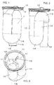
- FIGS. 1 to 6 a first embodiment of an inventive Absaugsiphons (Absauggeruchver gleiches) 1 is shown.
- the Absaugsiphon 1 is provided on its upper side with a in the drain opening of a drain basin, such as a urinal or wash basin, sealingly inserted plate 1.1, in which an inlet port 1.2 is formed.
- the plate 1.1 has at its peripheral edge on a seal holder 1.3.
- the seal holder 1.3 is formed for example by an annular groove 1.6, in which a sealing ring (not shown) can be used.
- the plate 1.1 is preferably formed circular disk-shaped.
- the collar 1.4 of the plate 1.1 defines a shell-like depression 1.7.
- a web-shaped projection 1.8 is formed as an assembly aid. This projection 1.8 can be taken eg with a pair of pliers.
- the inlet opening 1.2 is arranged eccentrically to the center M of the circular disk-shaped plate 1.1.
- the inlet opening 1.2 is spaced from the center M of the plate 1.1, wherein the edge of the inlet opening 1.2 can affect the center M (see. Fig. 8 ).
- a (first) substantially vertically to the plate 1.1 extending, vertically downwardly directed channel 1.9 is connected.
- an arcuate pipe part (channel part) 1.10 which represents a deflection, into a vertically upward channel 1.11 and from there into an arcuate deflection 1.12.
- the deflection edge 1.13 of the lower arcuate channel part 1.10 and the overflow edge 1.14 of the upper arcuate deflection 1.12 define the sealing water height H of the suction siphon 1.
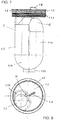
- a third channel 1.15 whose lower end defines the outlet 1.16 of the siphoning siphon 1, adjoins the upper arcuate deflection 1.12 in the direction of flow.
- the defined by the third channel 1.15 outlet 1.16 ends in the installed state of Absaugsiphons 1 free.
- the outlet 1.16 or the end of the third channel 1.15 is thus not connected in the installed state of the Absaugsiphons 1 with a drain line such that between the outlet and drain line a closed connection is formed.
- the outlet 1.16 of the suction siphon is preferably lower than the arcuate tubular part 1.10, which represents the transition from the first channel 1.9 to the second channel 1.11.
- the end of the third channel 1.15 thus opens free-standing and protrudes downwards with respect to the curved tubular part 1.10.
- the flow cross-sectional area or the inner diameter of the third channel 1.15 is reduced compared to the second channel 1.11.
- the average flow cross sectional area of the third channel 1.15 is in the range of 0.65 to 0.7 times the average flow cross sectional area of the second channel 1.11.
- FIGS. 4 to 6 It can be seen that the compared in the second channel 1.11 narrowed flow cross-sectional area of the third channel 1.15 of the cross-sectional reduction 1.17, which is provided immediately after the arcuate deflection 1.12, to the outlet 1.16 of Absaugsiphons 1 extends.
- the Absaugsiphon 1 is constructed of a plurality of plastic injection molded parts, which are gas-tightly connected to each other by welding or gluing.
- the three mutually parallel channels 1.9, 1.11, 1.15 of Absaugsiphons 1 are preferably formed from circular cylindrical tubes.
- the third channel 1.15 is arranged offset radially relative to the second channel 1.11.
- the third channel 1.15 is arranged offset radially relative to the first channel 1.9.
- the lateral surfaces of the first channel 1.9 and the second channel 1.11 are preferably connected directly touching each other (see. Fig. 6 ).
- the lateral surfaces of the second channel 1.11 and the third channel 1.15 are spaced apart and by a bridge-like web 1.18 interconnected.
- the channels or pipes 1.9, 1.11, 1.15 of the Absaug siphon 1 are considered in cross section within a circular envelope 1.19, whose diameter is greater than the sum of the outer diameter of the first and second channels 1.9, 1.11, but smaller than the sum of the outer diameter of all three channels or tubes 1.9, 1.11, 1.15 (cf. Fig. 6 ).
- the inlet of the suction siphon 1 is formed by a funnel-like section 1.20, which merges into the first channel 1.9.
- the inlet opening 1.2 defines the upper end 1.21 of the funnel-like section 1.20.
- the vertical distance between the upper end of 1.21 and the lower, in the first channel 1.9 merging end of the funnel-like portion 1.20 1.20 is in the illustrated embodiment about a quarter to a third of the sealing water height H Absaugsiphons the first
- Absaugsiphons 1 differs from that in the FIGS. 1 to 6 shown embodiment only in that the circular disk-shaped plate 1.1 is provided with an external thread 1.23, that is arranged below the seal holder 1.3.
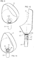
- FIGS. 9 to 14 different drainage basin 2, 3 or drainage channels 4 are shown, in which the Absaugsiphon 1 of the invention can be used.
- the Absaugsiphon 1 can be inserted from above into the drain opening of the respective drain basin 2, 3, 4 or screwed and removed upwards from the drain opening.
- FIGS. 9 to 11 show a urinal 2, in whose drain opening the Absaugsiphon 1 can be used sealingly with the plate 1.1.
- the drain opening of the urinal 2 or a drain pipe 2.1 fixed thereto has an annular shoulder 2.2, on which the plate 1.1 is placed, so that in the seal receptacle (1.3) arranged sealing ring radially sealing against the annular groove (1.6) of the plate 1.1 and against the inner circumference of paragraph 2.2 of the drain pipe 2.1 and the drain basin 2 is pressed (see. Figures 2 and 4 ).
- Fig. 10 It can be seen that the outlet end 1.16 'of the suction siphon 1 inserted into the drainage pipe 2.1 discharges free-standing, ie forms no closed connection with the drainage pipe 2.1.
- Absaugsiphons 1 is covered by a plate-shaped cover 1.24, whose bottom defines a water inlet gap 1.25 and which is releasably connected to the Absaugsiphon 1.
- Fig. 12 a section of a washbasin 3 is shown, the drain opening is provided with an internal thread 3.1, in which a Absaugsiphon 1 according to Fig. 7 is screwed sealingly.
- a Absaugsiphon 1 according to Fig. 7 is screwed sealingly.
- FIGS. 13 and 14 show a trough-shaped drainage basin 4, for example, a launder, whose drain opening according to the in Fig. 12 illustrated embodiment is provided with an internal thread 4.1, in which a Absaugsiphon 1 according to Fig. 7 is screwed sealingly.
- the cover 1.24 may also be designed such that it can be detachably connected to a pipe socket-shaped, an external thread having, attachable to the drain opening of the drain basin 2, 3 or 4 clamping part.
- the suction siphon 1 according to the invention or the circular disk-shaped plate 1.1 instead of an external thread 1.23 according to FIG Fig. 7 also be provided for example with a bayonet lock.
Landscapes
- Engineering & Computer Science (AREA)
- Health & Medical Sciences (AREA)
- Life Sciences & Earth Sciences (AREA)
- Hydrology & Water Resources (AREA)
- Public Health (AREA)
- Water Supply & Treatment (AREA)
- Environmental & Geological Engineering (AREA)
- Sanitary Device For Flush Toilet (AREA)
- Sink And Installation For Waste Water (AREA)
Claims (10)
- Armature d'écoulement pour cuve d'écoulement (2, 3, 4), en particulier un urinoir ou un lavabo, avec un siphon d'aspiration (1) qui définit un siphon et présente une entrée (1.2), qui est raccordée à une ouverture d'écoulement de la cuve d'écoulement, et qui présente une sortie (1.16), où le siphon d'aspiration (1) peut être monté par le haut dans la sortie d'écoulement de la cuve d'écoulement (2, 3, 4) et démonté de cette ouverture d'écoulement vers le haut, et présente, par segment, trois canaux essentiellement parallèles les uns aux autres (1.9, 1.11, 1.15), où le liquide qui entre dans le siphon d'aspiration peut être dirigé vers le bas par le premier (1.9) des trois canaux, pendant que le liquide dirigé vers le bas par le premier canal (1.9) peut être dirigé à nouveau vers le haut par le deuxième (1.11) des trois canaux, et où le liquide guidé vers le haut par le deuxième canal (1.11) peut être dirigé vers le bas et vers la sortie (1.16) par le troisième (1.15) des trois canaux, le troisième canal (1.15) présentant une section transversale d'écoulement rétrécie par rapport au deuxième canal (1.11), la section transversale d'écoulement moyenne du troisième canal (1.15) est inférieure, au moins sur un segment qui fait au moins 0,5 fois la hauteur de la garde d'eau (H) du siphon, à la section transversale moyenne d'écoulement du deuxième canal (1.11) et où la sortie (1.16) définie par le troisième canal (1.15) présentant une extrémité libre à l'état monté du siphon d'aspiration (1), où la sortie (1.16) du siphon d'aspiration (1) est plus profonde que une partie de tuyau courbe (1.10) qui définit la transition du premier canal (1.9) au deuxième canal (1.11),
caractérisée en ce que la section transversale moyenne du troisième canal (1.15) se situe dans l'intervalle allant de 0,6 fois à 0,85 fois la section transversale moyenne d'écoulement du deuxième canal (1.11), où la section longitudinale du troisième canal (1.15), qui présente une section transversale d'écoulement rétrécie par rapport au deuxième canal (1.11), est linéaire jusqu'à la sortie (1.16) du siphon d'aspiration. - Armature d'écoulement selon la revendication 1, caractérisée en ce que la section transversale d'écoulement du troisième canal (1.15), rétrécie par rapport au deuxième canal (1.11) s'étend jusqu'à la sortie (1.16) du siphon d'aspiration.
- Armature d'écoulement selon la revendication 1 ou 2, caractérisée en ce que l'entrée du siphon d'aspiration est formée d'un segment en forme d'entonnoir (1.20), qui devient le premier canal (1.9), où la distance entre l'extrémité supérieure (1.21) et l'extrémité inférieure (1.22) devenant le premier canal du segment en forme d'entonnoir (1.20) fait au moins 15%, de préférence au moins 25% de la hauteur de garde d'eau (H) du siphon d'aspiration.
- Armature d'écoulement selon l'une quelconque des revendications 1 à 3, caractérisée en ce que le siphon d'aspiration (1) est muni d'une plaque (1.1) circulaire présentant une ouverture d'entrée (1.2), dont le bord périphérique présente un siège de joint (1.3), où l'ouverture d'entrée (1.2) est agencée de manière excentrique, de préférence distante du centre (M) de la plaque circulaire (1.1).
- Armature d'écoulement selon les revendications 3 et 4, caractérisée en ce que l'ouverture d'entrée (1.2) définit l'extrémité supérieure (1.21) du segment en forme d'entonnoir (1.20) .
- Armature d'écoulement selon la revendication 4 ou 5, caractérisée en ce que la plaque circulaire (1.1) présente un filet extérieur (1.23) sous le siège de joint (1.3).
- Armature d'écoulement selon l'une quelconque des revendications 4 à 6, caractérisée en ce que la plaque circulaire (1.1) présente sur sa face supérieure, au moins une saillie (1.8) en forme de cône ou de tige comme aide au montage.
- Armature d'écoulement selon l'une quelconque des revendications 1 à 7, caractérisée en ce que les trois canaux (1.9, 1.11, 1.15) parallèles les uns aux autres du siphon d'aspiration (1) ont la forme de tubes cylindriques circulaires.
- Armature d'écoulement selon l'une quelconque des revendications 1 à 8, caractérisée en ce que le troisième canal (1.15) est radialement décalé au moins par rapport au deuxième canal (1.11).
- Armature d'écoulement selon l'une quelconque des revendications 1 à 9, caractérisée en ce que l'entrée du siphon d'aspiration est couverte d'un couvercle en forme d'assiette (1.24), dont la face inférieure limite une fente d'arrivée d'eau (1.25) et qui est reliée de manière amovible au siphon d'aspiration (1) et/ou une pièce de serrage de type tubulure, présentant un filet extérieur et pouvant être fixée à l'ouverture de sortie de la cuve d'écoulement.
Priority Applications (1)
| Application Number | Priority Date | Filing Date | Title |
|---|---|---|---|
| PL13158875T PL2664721T3 (pl) | 2012-05-18 | 2013-03-13 | Armatura odpływowa do basenu odpływowego, w szczególności do pisuaru, z syfonem odsysającym |
Applications Claiming Priority (1)
| Application Number | Priority Date | Filing Date | Title |
|---|---|---|---|
| DE102012104325A DE102012104325B3 (de) | 2012-05-18 | 2012-05-18 | Ablaufarmatur für ein Ablaufbecken, insbesondere Urinal, mit einem Absaugsiphon |
Publications (3)
| Publication Number | Publication Date |
|---|---|
| EP2664721A2 EP2664721A2 (fr) | 2013-11-20 |
| EP2664721A3 EP2664721A3 (fr) | 2015-01-21 |
| EP2664721B1 true EP2664721B1 (fr) | 2018-09-05 |
Family
ID=47877887
Family Applications (1)
| Application Number | Title | Priority Date | Filing Date |
|---|---|---|---|
| EP13158875.8A Active EP2664721B1 (fr) | 2012-05-18 | 2013-03-13 | Armature d'écoulement pour cuve d'écoulement, notamment urinoir, comportant un siphon d'aspiration |
Country Status (4)
| Country | Link |
|---|---|
| EP (1) | EP2664721B1 (fr) |
| DE (1) | DE102012104325B3 (fr) |
| ES (1) | ES2692189T3 (fr) |
| PL (1) | PL2664721T3 (fr) |
Citations (1)
| Publication number | Priority date | Publication date | Assignee | Title |
|---|---|---|---|---|
| DE318264C (fr) * |
Family Cites Families (9)
| Publication number | Priority date | Publication date | Assignee | Title |
|---|---|---|---|---|
| US172865A (en) * | 1876-02-01 | Improvement in stench-traps | ||
| FR732502A (fr) * | 1931-03-02 | 1932-09-21 | Perfectionnements apportés aux bondes siphoïdes pour éviers, postes d'eau, lavabos ou semblables | |
| DE2447695C3 (de) * | 1974-10-07 | 1978-10-12 | Fa. Franz Viegener Ii, 5952 Attendorn | Absaugvorrichtung mit Geruchverschluß für Urinale |
| DE4227574A1 (de) * | 1992-08-20 | 1994-02-24 | Wella Ag | Siphon |
| IL139365A (en) * | 1998-05-05 | 2004-06-20 | Keller Hans | Stink trap for a variable |
| EP1335076B1 (fr) * | 2002-02-11 | 2005-06-01 | Geberit Technik Ag | Accessoire d'écoulement pour un dispositif sanitaire, en particulier un urinoir |
| EP1574629B1 (fr) * | 2004-03-12 | 2010-05-12 | Geberit International AG | Armature d'écoulement pour un dispositif sanitaire, spécialement pour une cuvette de douche |
| ATE509163T1 (de) * | 2006-03-25 | 2011-05-15 | Dallmer Gmbh & Co Kg | Urinal |
| JP5700484B2 (ja) * | 2009-09-29 | 2015-04-15 | 株式会社Lixil | 小便器用排水トラップ |
-
2012
- 2012-05-18 DE DE102012104325A patent/DE102012104325B3/de active Active
-
2013
- 2013-03-13 EP EP13158875.8A patent/EP2664721B1/fr active Active
- 2013-03-13 ES ES13158875.8T patent/ES2692189T3/es active Active
- 2013-03-13 PL PL13158875T patent/PL2664721T3/pl unknown
Patent Citations (1)
| Publication number | Priority date | Publication date | Assignee | Title |
|---|---|---|---|---|
| DE318264C (fr) * |
Also Published As
| Publication number | Publication date |
|---|---|
| PL2664721T3 (pl) | 2018-12-31 |
| ES2692189T3 (es) | 2018-11-30 |
| EP2664721A2 (fr) | 2013-11-20 |
| DE102012104325B3 (de) | 2013-11-21 |
| EP2664721A3 (fr) | 2015-01-21 |
Similar Documents
| Publication | Publication Date | Title |
|---|---|---|
| EP2045403B1 (fr) | Garniture d'ecoulement avec trop-plein intégré | |
| EP2363543B1 (fr) | Garniture d'écoulement dotée d'une ouverture de nettoyage | |
| EP2453065A2 (fr) | Garniture d'écoulement dotée d'un passage de surplein positionnable de manière invisible | |
| EP2426283A2 (fr) | Siphon polyvalent | |
| EP1288379A1 (fr) | Bouche d'écoulement pour lavabo avec une sortie en forme de fente | |
| EP2711475B1 (fr) | Evier avec un dispositif d'évacuation aéré | |
| EP1335076B1 (fr) | Accessoire d'écoulement pour un dispositif sanitaire, en particulier un urinoir | |
| DE102008038274B3 (de) | Ablauf | |
| DE202008011010U1 (de) | Ablauf | |
| DE19741827B4 (de) | Ablaufarmatur für Bade- oder Duschwannen | |
| EP2014840A2 (fr) | Garniture d'écoulement pour douches ou baignoires | |
| EP2258905B1 (fr) | Écoulement, notamment pour des dispositifs sanitaires | |
| EP2808458A1 (fr) | Dispositif d'écoulement d'eau pour une douche et élément de sol de douche | |
| EP1862602B1 (fr) | Réservoir doté d'un trop-plein recouvert et garniture d'écoulement correspondante | |
| EP1447485A2 (fr) | Dispositif d'écoulement | |
| EP2664721B1 (fr) | Armature d'écoulement pour cuve d'écoulement, notamment urinoir, comportant un siphon d'aspiration | |
| DE10360310A1 (de) | Ablaufvorrichtung | |
| DE10201347A1 (de) | Einlaufvorrichtung für die Abführung von Regenwasser von einem Dach | |
| DE102010044940B4 (de) | Abwasserablauf mit Geruchsverschluss | |
| WO2005111326A1 (fr) | Siphon | |
| DE10204683B4 (de) | Becken | |
| EP2434063B1 (fr) | Ecoulement d'eau usée doté d'un siphon, notamment pour bac à douche | |
| EP1775395A1 (fr) | Dispositif d'écoulement pour installations sanitaires | |
| DE2522425A1 (de) | Geruchverschluss fuer abwasserbehaelter | |
| EP3567169B1 (fr) | Raccord fileté d'évacuation |
Legal Events
| Date | Code | Title | Description |
|---|---|---|---|
| PUAI | Public reference made under article 153(3) epc to a published international application that has entered the european phase |
Free format text: ORIGINAL CODE: 0009012 |
|
| AK | Designated contracting states |
Kind code of ref document: A2 Designated state(s): AL AT BE BG CH CY CZ DE DK EE ES FI FR GB GR HR HU IE IS IT LI LT LU LV MC MK MT NL NO PL PT RO RS SE SI SK SM TR |
|
| AX | Request for extension of the european patent |
Extension state: BA ME |
|
| PUAL | Search report despatched |
Free format text: ORIGINAL CODE: 0009013 |
|
| AK | Designated contracting states |
Kind code of ref document: A3 Designated state(s): AL AT BE BG CH CY CZ DE DK EE ES FI FR GB GR HR HU IE IS IT LI LT LU LV MC MK MT NL NO PL PT RO RS SE SI SK SM TR |
|
| AX | Request for extension of the european patent |
Extension state: BA ME |
|
| RIC1 | Information provided on ipc code assigned before grant |
Ipc: E03C 1/29 20060101ALI20141216BHEP Ipc: E03C 1/284 20060101ALI20141216BHEP Ipc: E03D 13/00 20060101AFI20141216BHEP |
|
| 17P | Request for examination filed |
Effective date: 20150224 |
|
| RBV | Designated contracting states (corrected) |
Designated state(s): AL AT BE BG CH CY CZ DE DK EE ES FI FR GB GR HR HU IE IS IT LI LT LU LV MC MK MT NL NO PL PT RO RS SE SI SK SM TR |
|
| RAP1 | Party data changed (applicant data changed or rights of an application transferred) |
Owner name: VIEGA GMBH & CO. KG |
|
| STAA | Information on the status of an ep patent application or granted ep patent |
Free format text: STATUS: EXAMINATION IS IN PROGRESS |
|
| 17Q | First examination report despatched |
Effective date: 20161024 |
|
| RAP1 | Party data changed (applicant data changed or rights of an application transferred) |
Owner name: VIEGA TECHNOLOGY GMBH & CO. KG |
|
| GRAP | Despatch of communication of intention to grant a patent |
Free format text: ORIGINAL CODE: EPIDOSNIGR1 |
|
| STAA | Information on the status of an ep patent application or granted ep patent |
Free format text: STATUS: GRANT OF PATENT IS INTENDED |
|
| INTG | Intention to grant announced |
Effective date: 20180405 |
|
| GRAJ | Information related to disapproval of communication of intention to grant by the applicant or resumption of examination proceedings by the epo deleted |
Free format text: ORIGINAL CODE: EPIDOSDIGR1 |
|
| STAA | Information on the status of an ep patent application or granted ep patent |
Free format text: STATUS: EXAMINATION IS IN PROGRESS |
|
| GRAP | Despatch of communication of intention to grant a patent |
Free format text: ORIGINAL CODE: EPIDOSNIGR1 |
|
| STAA | Information on the status of an ep patent application or granted ep patent |
Free format text: STATUS: GRANT OF PATENT IS INTENDED |
|
| INTC | Intention to grant announced (deleted) | ||
| INTG | Intention to grant announced |
Effective date: 20180528 |
|
| GRAS | Grant fee paid |
Free format text: ORIGINAL CODE: EPIDOSNIGR3 |
|
| GRAA | (expected) grant |
Free format text: ORIGINAL CODE: 0009210 |
|
| STAA | Information on the status of an ep patent application or granted ep patent |
Free format text: STATUS: THE PATENT HAS BEEN GRANTED |
|
| AK | Designated contracting states |
Kind code of ref document: B1 Designated state(s): AL AT BE BG CH CY CZ DE DK EE ES FI FR GB GR HR HU IE IS IT LI LT LU LV MC MK MT NL NO PL PT RO RS SE SI SK SM TR |
|
| REG | Reference to a national code |
Ref country code: GB Ref legal event code: FG4D Free format text: NOT ENGLISH |
|
| REG | Reference to a national code |
Ref country code: CH Ref legal event code: EP |
|
| REG | Reference to a national code |
Ref country code: AT Ref legal event code: REF Ref document number: 1037968 Country of ref document: AT Kind code of ref document: T Effective date: 20180915 |
|
| REG | Reference to a national code |
Ref country code: IE Ref legal event code: FG4D Free format text: LANGUAGE OF EP DOCUMENT: GERMAN |
|
| REG | Reference to a national code |
Ref country code: DE Ref legal event code: R096 Ref document number: 502013010996 Country of ref document: DE |
|
| REG | Reference to a national code |
Ref country code: CH Ref legal event code: NV Representative=s name: SCHMAUDER AND PARTNER AG PATENT- UND MARKENANW, CH |
|
| REG | Reference to a national code |
Ref country code: NL Ref legal event code: FP |
|
| REG | Reference to a national code |
Ref country code: SE Ref legal event code: TRGR |
|
| REG | Reference to a national code |
Ref country code: ES Ref legal event code: FG2A Ref document number: 2692189 Country of ref document: ES Kind code of ref document: T3 Effective date: 20181130 |
|
| REG | Reference to a national code |
Ref country code: LT Ref legal event code: MG4D |
|
| PG25 | Lapsed in a contracting state [announced via postgrant information from national office to epo] |
Ref country code: FI Free format text: LAPSE BECAUSE OF FAILURE TO SUBMIT A TRANSLATION OF THE DESCRIPTION OR TO PAY THE FEE WITHIN THE PRESCRIBED TIME-LIMIT Effective date: 20180905 Ref country code: RS Free format text: LAPSE BECAUSE OF FAILURE TO SUBMIT A TRANSLATION OF THE DESCRIPTION OR TO PAY THE FEE WITHIN THE PRESCRIBED TIME-LIMIT Effective date: 20180905 Ref country code: NO Free format text: LAPSE BECAUSE OF FAILURE TO SUBMIT A TRANSLATION OF THE DESCRIPTION OR TO PAY THE FEE WITHIN THE PRESCRIBED TIME-LIMIT Effective date: 20181205 Ref country code: GR Free format text: LAPSE BECAUSE OF FAILURE TO SUBMIT A TRANSLATION OF THE DESCRIPTION OR TO PAY THE FEE WITHIN THE PRESCRIBED TIME-LIMIT Effective date: 20181206 Ref country code: BG Free format text: LAPSE BECAUSE OF FAILURE TO SUBMIT A TRANSLATION OF THE DESCRIPTION OR TO PAY THE FEE WITHIN THE PRESCRIBED TIME-LIMIT Effective date: 20181205 Ref country code: LT Free format text: LAPSE BECAUSE OF FAILURE TO SUBMIT A TRANSLATION OF THE DESCRIPTION OR TO PAY THE FEE WITHIN THE PRESCRIBED TIME-LIMIT Effective date: 20180905 |
|
| PG25 | Lapsed in a contracting state [announced via postgrant information from national office to epo] |
Ref country code: HR Free format text: LAPSE BECAUSE OF FAILURE TO SUBMIT A TRANSLATION OF THE DESCRIPTION OR TO PAY THE FEE WITHIN THE PRESCRIBED TIME-LIMIT Effective date: 20180905 Ref country code: LV Free format text: LAPSE BECAUSE OF FAILURE TO SUBMIT A TRANSLATION OF THE DESCRIPTION OR TO PAY THE FEE WITHIN THE PRESCRIBED TIME-LIMIT Effective date: 20180905 Ref country code: AL Free format text: LAPSE BECAUSE OF FAILURE TO SUBMIT A TRANSLATION OF THE DESCRIPTION OR TO PAY THE FEE WITHIN THE PRESCRIBED TIME-LIMIT Effective date: 20180905 |
|
| PG25 | Lapsed in a contracting state [announced via postgrant information from national office to epo] |
Ref country code: CZ Free format text: LAPSE BECAUSE OF FAILURE TO SUBMIT A TRANSLATION OF THE DESCRIPTION OR TO PAY THE FEE WITHIN THE PRESCRIBED TIME-LIMIT Effective date: 20180905 Ref country code: IS Free format text: LAPSE BECAUSE OF FAILURE TO SUBMIT A TRANSLATION OF THE DESCRIPTION OR TO PAY THE FEE WITHIN THE PRESCRIBED TIME-LIMIT Effective date: 20190105 Ref country code: RO Free format text: LAPSE BECAUSE OF FAILURE TO SUBMIT A TRANSLATION OF THE DESCRIPTION OR TO PAY THE FEE WITHIN THE PRESCRIBED TIME-LIMIT Effective date: 20180905 Ref country code: EE Free format text: LAPSE BECAUSE OF FAILURE TO SUBMIT A TRANSLATION OF THE DESCRIPTION OR TO PAY THE FEE WITHIN THE PRESCRIBED TIME-LIMIT Effective date: 20180905 |
|
| PG25 | Lapsed in a contracting state [announced via postgrant information from national office to epo] |
Ref country code: SM Free format text: LAPSE BECAUSE OF FAILURE TO SUBMIT A TRANSLATION OF THE DESCRIPTION OR TO PAY THE FEE WITHIN THE PRESCRIBED TIME-LIMIT Effective date: 20180905 Ref country code: SK Free format text: LAPSE BECAUSE OF FAILURE TO SUBMIT A TRANSLATION OF THE DESCRIPTION OR TO PAY THE FEE WITHIN THE PRESCRIBED TIME-LIMIT Effective date: 20180905 Ref country code: PT Free format text: LAPSE BECAUSE OF FAILURE TO SUBMIT A TRANSLATION OF THE DESCRIPTION OR TO PAY THE FEE WITHIN THE PRESCRIBED TIME-LIMIT Effective date: 20190105 |
|
| REG | Reference to a national code |
Ref country code: DE Ref legal event code: R097 Ref document number: 502013010996 Country of ref document: DE |
|
| PLBE | No opposition filed within time limit |
Free format text: ORIGINAL CODE: 0009261 |
|
| STAA | Information on the status of an ep patent application or granted ep patent |
Free format text: STATUS: NO OPPOSITION FILED WITHIN TIME LIMIT |
|
| PG25 | Lapsed in a contracting state [announced via postgrant information from national office to epo] |
Ref country code: DK Free format text: LAPSE BECAUSE OF FAILURE TO SUBMIT A TRANSLATION OF THE DESCRIPTION OR TO PAY THE FEE WITHIN THE PRESCRIBED TIME-LIMIT Effective date: 20180905 |
|
| 26N | No opposition filed |
Effective date: 20190606 |
|
| PG25 | Lapsed in a contracting state [announced via postgrant information from national office to epo] |
Ref country code: SI Free format text: LAPSE BECAUSE OF FAILURE TO SUBMIT A TRANSLATION OF THE DESCRIPTION OR TO PAY THE FEE WITHIN THE PRESCRIBED TIME-LIMIT Effective date: 20180905 |
|
| PG25 | Lapsed in a contracting state [announced via postgrant information from national office to epo] |
Ref country code: MC Free format text: LAPSE BECAUSE OF FAILURE TO SUBMIT A TRANSLATION OF THE DESCRIPTION OR TO PAY THE FEE WITHIN THE PRESCRIBED TIME-LIMIT Effective date: 20180905 |
|
| PG25 | Lapsed in a contracting state [announced via postgrant information from national office to epo] |
Ref country code: LU Free format text: LAPSE BECAUSE OF NON-PAYMENT OF DUE FEES Effective date: 20190313 |
|
| REG | Reference to a national code |
Ref country code: BE Ref legal event code: MM Effective date: 20190331 |
|
| PG25 | Lapsed in a contracting state [announced via postgrant information from national office to epo] |
Ref country code: IE Free format text: LAPSE BECAUSE OF NON-PAYMENT OF DUE FEES Effective date: 20190313 |
|
| PG25 | Lapsed in a contracting state [announced via postgrant information from national office to epo] |
Ref country code: BE Free format text: LAPSE BECAUSE OF NON-PAYMENT OF DUE FEES Effective date: 20190331 |
|
| PG25 | Lapsed in a contracting state [announced via postgrant information from national office to epo] |
Ref country code: TR Free format text: LAPSE BECAUSE OF FAILURE TO SUBMIT A TRANSLATION OF THE DESCRIPTION OR TO PAY THE FEE WITHIN THE PRESCRIBED TIME-LIMIT Effective date: 20180905 |
|
| PG25 | Lapsed in a contracting state [announced via postgrant information from national office to epo] |
Ref country code: MT Free format text: LAPSE BECAUSE OF FAILURE TO SUBMIT A TRANSLATION OF THE DESCRIPTION OR TO PAY THE FEE WITHIN THE PRESCRIBED TIME-LIMIT Effective date: 20180905 |
|
| PG25 | Lapsed in a contracting state [announced via postgrant information from national office to epo] |
Ref country code: CY Free format text: LAPSE BECAUSE OF FAILURE TO SUBMIT A TRANSLATION OF THE DESCRIPTION OR TO PAY THE FEE WITHIN THE PRESCRIBED TIME-LIMIT Effective date: 20180905 |
|
| PG25 | Lapsed in a contracting state [announced via postgrant information from national office to epo] |
Ref country code: HU Free format text: LAPSE BECAUSE OF FAILURE TO SUBMIT A TRANSLATION OF THE DESCRIPTION OR TO PAY THE FEE WITHIN THE PRESCRIBED TIME-LIMIT; INVALID AB INITIO Effective date: 20130313 |
|
| PGFP | Annual fee paid to national office [announced via postgrant information from national office to epo] |
Ref country code: AT Payment date: 20220322 Year of fee payment: 10 |
|
| PGFP | Annual fee paid to national office [announced via postgrant information from national office to epo] |
Ref country code: PL Payment date: 20220307 Year of fee payment: 10 |
|
| PG25 | Lapsed in a contracting state [announced via postgrant information from national office to epo] |
Ref country code: MK Free format text: LAPSE BECAUSE OF FAILURE TO SUBMIT A TRANSLATION OF THE DESCRIPTION OR TO PAY THE FEE WITHIN THE PRESCRIBED TIME-LIMIT Effective date: 20180905 |
|
| PGFP | Annual fee paid to national office [announced via postgrant information from national office to epo] |
Ref country code: FR Payment date: 20230323 Year of fee payment: 11 |
|
| PGFP | Annual fee paid to national office [announced via postgrant information from national office to epo] |
Ref country code: IT Payment date: 20230323 Year of fee payment: 11 Ref country code: GB Payment date: 20230322 Year of fee payment: 11 |
|
| PGFP | Annual fee paid to national office [announced via postgrant information from national office to epo] |
Ref country code: NL Payment date: 20230322 Year of fee payment: 11 |
|
| REG | Reference to a national code |
Ref country code: AT Ref legal event code: MM01 Ref document number: 1037968 Country of ref document: AT Kind code of ref document: T Effective date: 20230313 |
|
| PG25 | Lapsed in a contracting state [announced via postgrant information from national office to epo] |
Ref country code: AT Free format text: LAPSE BECAUSE OF NON-PAYMENT OF DUE FEES Effective date: 20230313 |
|
| PG25 | Lapsed in a contracting state [announced via postgrant information from national office to epo] |
Ref country code: PL Free format text: LAPSE BECAUSE OF NON-PAYMENT OF DUE FEES Effective date: 20230313 |
|
| PG25 | Lapsed in a contracting state [announced via postgrant information from national office to epo] |
Ref country code: PL Free format text: LAPSE BECAUSE OF NON-PAYMENT OF DUE FEES Effective date: 20230313 |
|
| REG | Reference to a national code |
Ref country code: NL Ref legal event code: MM Effective date: 20240401 |
|
| GBPC | Gb: european patent ceased through non-payment of renewal fee |
Effective date: 20240313 |
|
| PG25 | Lapsed in a contracting state [announced via postgrant information from national office to epo] |
Ref country code: NL Free format text: LAPSE BECAUSE OF NON-PAYMENT OF DUE FEES Effective date: 20240401 |
|
| PG25 | Lapsed in a contracting state [announced via postgrant information from national office to epo] |
Ref country code: NL Free format text: LAPSE BECAUSE OF NON-PAYMENT OF DUE FEES Effective date: 20240401 |
|
| PG25 | Lapsed in a contracting state [announced via postgrant information from national office to epo] |
Ref country code: GB Free format text: LAPSE BECAUSE OF NON-PAYMENT OF DUE FEES Effective date: 20240313 |
|
| PG25 | Lapsed in a contracting state [announced via postgrant information from national office to epo] |
Ref country code: FR Free format text: LAPSE BECAUSE OF NON-PAYMENT OF DUE FEES Effective date: 20240331 |
|
| PG25 | Lapsed in a contracting state [announced via postgrant information from national office to epo] |
Ref country code: GB Free format text: LAPSE BECAUSE OF NON-PAYMENT OF DUE FEES Effective date: 20240313 Ref country code: FR Free format text: LAPSE BECAUSE OF NON-PAYMENT OF DUE FEES Effective date: 20240331 |
|
| PG25 | Lapsed in a contracting state [announced via postgrant information from national office to epo] |
Ref country code: IT Free format text: LAPSE BECAUSE OF NON-PAYMENT OF DUE FEES Effective date: 20240313 |
|
| PGFP | Annual fee paid to national office [announced via postgrant information from national office to epo] |
Ref country code: ES Payment date: 20250428 Year of fee payment: 13 |
|
| PGFP | Annual fee paid to national office [announced via postgrant information from national office to epo] |
Ref country code: CH Payment date: 20250401 Year of fee payment: 13 |
|
| REG | Reference to a national code |
Ref country code: CH Ref legal event code: U11 Free format text: ST27 STATUS EVENT CODE: U-0-0-U10-U11 (AS PROVIDED BY THE NATIONAL OFFICE) Effective date: 20260401 |
|
| PGFP | Annual fee paid to national office [announced via postgrant information from national office to epo] |
Ref country code: SE Payment date: 20260327 Year of fee payment: 14 |
|
| PGFP | Annual fee paid to national office [announced via postgrant information from national office to epo] |
Ref country code: DE Payment date: 20260327 Year of fee payment: 14 |