EP2664721B1 - Ablaufarmatur für ein ablaufbecken, insbesondere urinal, mit einem absaugsiphon - Google Patents
Ablaufarmatur für ein ablaufbecken, insbesondere urinal, mit einem absaugsiphon Download PDFInfo
- Publication number
- EP2664721B1 EP2664721B1 EP13158875.8A EP13158875A EP2664721B1 EP 2664721 B1 EP2664721 B1 EP 2664721B1 EP 13158875 A EP13158875 A EP 13158875A EP 2664721 B1 EP2664721 B1 EP 2664721B1
- Authority
- EP
- European Patent Office
- Prior art keywords
- channel
- drainage
- suction siphon
- outlet
- flow cross
- Prior art date
- Legal status (The legal status is an assumption and is not a legal conclusion. Google has not performed a legal analysis and makes no representation as to the accuracy of the status listed.)
- Active
Links
Images


Classifications
-
- E—FIXED CONSTRUCTIONS
- E03—WATER SUPPLY; SEWERAGE
- E03C—DOMESTIC PLUMBING INSTALLATIONS FOR FRESH WATER OR WASTE WATER; SINKS
- E03C1/00—Domestic plumbing installations for fresh water or waste water; Sinks
- E03C1/12—Plumbing installations for waste water; Basins or fountains connected thereto; Sinks
- E03C1/28—Odour seals
- E03C1/284—Odour seals having U-shaped trap
-
- E—FIXED CONSTRUCTIONS
- E03—WATER SUPPLY; SEWERAGE
- E03C—DOMESTIC PLUMBING INSTALLATIONS FOR FRESH WATER OR WASTE WATER; SINKS
- E03C1/00—Domestic plumbing installations for fresh water or waste water; Sinks
- E03C1/12—Plumbing installations for waste water; Basins or fountains connected thereto; Sinks
- E03C1/28—Odour seals
- E03C1/29—Odour seals having housing containing dividing wall, e.g. tubular
-
- E—FIXED CONSTRUCTIONS
- E03—WATER SUPPLY; SEWERAGE
- E03D—WATER-CLOSETS OR URINALS WITH FLUSHING DEVICES; FLUSHING VALVES THEREFOR
- E03D13/00—Urinals ; Means for connecting the urinal to the flushing pipe and the wastepipe; Splashing shields for urinals
Definitions
- the invention relates to a drainage fitting for a drainage basin, in particular urinal or washbasin, with a suction siphon, which defines an odor trap and has an inlet to be connected to a drain opening of the drainage basin, and which has an outlet, wherein the Absaugsiphon from above into the drain opening can be used of the drain basin and can be removed from this drain opening and sections three substantially parallel channels, wherein the first of the three channels in the Absaugsiphon occurred liquid can be guided down, while through the second of the three channels of the the first channel downwardly guided liquid can be guided back up, and wherein the third channel from the second channel upwardly guided liquid can be guided down to the outlet, wherein the third channel is narrowed relative to the second channel Strömungsquersch wherein the average flow cross-sectional area of the third channel is smaller than the average flow cross-sectional area of the second channel at least along a height portion that is at least 0.5 times the sealing water level of the odor trap, and wherein the outlet defined by the third channel is
- a urinal is known with a drainage device having an exchangeable odor-closure unit.
- the odor closure unit is designed such that it can be introduced from above through the drainage opening of the urinal into the drainage device.
- the Odor closure unit has a cylindrical outer contour, the cylinder axis extends substantially vertically in the installed state of the odor obturator.
- the odor-occlusion unit has, in sections, three channels running parallel to one another, wherein liquid which has entered the odor-occlusion unit through the first of the three channels can be led downwards.
- the liquid guided downwards from the first channel can then be led back upwards, while finally the liquid guided upwards from the second channel can be guided downwards by the third channel, so that it leaves the odor closure unit can emerge.
- This known odor-trap unit is designed such that it operates essentially only according to the displacement principle, ie an amount of liquid entering the odor-trap unit displaces a corresponding amount of liquid from the odor-trap unit.
- the suction siphon has an inlet which is to be connected to a drainage opening of a urinal or sanitary body. Further, the suction siphon has an outlet to be connected to a drain line for establishing a closed connection between the outlet and the drain line, the outlet projecting downwards and being pluggable.
- the Absaugsiphon can be used from above into the drain opening of the sanitary body and expandable from this drain opening. For the production of the plug connection between outlet and discharge line this Absaugsiphon must be correctly positioned in the discharge opening of the Sanitary body are used.
- the Absaugsiphon communicates with a sump, which is defined by a discharge bend of the drain line.
- the JP-A-2011 94473 discloses a drainage fitting for a urinal, with a suction siphon that defines an odor trap and can be inserted from above into the drainage opening of the urinal and expanded upwards from this drainage opening.
- the Absaugsiphon has sections three substantially mutually parallel channels, wherein the first of the three channels in the Absaugsiphon occurred liquid can be guided downwards, while through the second of the three channels from the first channel downwardly guided liquid back up can be guided, and of the third channel of the second channel upwardly guided liquid can be guided down to the outlet of Absaugsiphons.
- the third channel has a narrowed compared to the second channel flow cross-sectional area, wherein the average flow cross-sectional area of the third channel at least along a height portion which is at least half the barrier water height of the odor trap is significantly smaller than the average flow cross-sectional area of the second channel.
- the defined by the third channel outlet of Absaugsiphons ends in its installed state freely in the drain fitting.
- US 172 865 A discloses a drain fitting according to the preamble of claim 1.
- the present invention has for its object to provide a waste set of the type mentioned, in which the exchange of water in the odor trap should take place even with a relatively small amount of liquid with low fluid intake and also optionally Floats must be removed, and in which the Absaugsiphon can be used in the drain opening of the drain basin largely rotational position independent of the running through the drain opening vertical central axis sealing.
- the drainage device according to the invention or its Absaugsiphon is characterized in that the average flow cross-sectional area of the third channel of Absaugsiphons is in the range of 0.6 times to 0.85 times the average flow cross-sectional area of the second channel, wherein the outlet of Absaugsiphons is lower than an arcuate tubular member defining the transition from the first channel to the second channel, and wherein the length portion of the third channel having the restricted compared to the second channel flow cross-sectional area, is formed straight up to the outlet of Absaugsiphons.
- the constriction of the third channel ensures that in the Absaugsiphon a water exchange takes place even at relatively low flushing volume and also floating material are removed with.
- the Absaugsiphon invention can be largely used rotationally independent in the drain opening of the drain tank, since he does not require the production of a closed connection between Siphonauslass and drain line for its function.
- the drain fitting according to the invention or the Absaugsiphon invention can be used in different drain basins, especially in sanitary drainage basins such as urinals, urinal troughs, sinks, wash troughs and showers, but also in industrial drainage basins and gutters, e.g. in sinks of industrial plants or in water drainage channels of car washes.
- the drainage device according to the invention or the Absaugsiphon invention is thus basically universally applicable.
- the water exchange in the odor trap can be particularly reliable with a relatively small flushing volume be ensured.
- the outlet of the Absaugsiphons is lower according to the invention as an arcuate pipe part which defines the transition from the first channel to the second channel.
- the length section of the third channel which has the flow cross-sectional area narrowed in relation to the second channel, is formed in a straight line up to the outlet of the suction siphon.
- the three mutually parallel channels of Absaugsiphons can be formed from circular cylindrical tubes.
- a preferred embodiment of the invention is characterized in that the narrowed compared to the second channel flow cross-sectional area of the third channel extends to the outlet of Absaugsiphons.
- a further preferred embodiment of the invention provides that the inlet of Absaugsiphons is formed by a funnel-like portion which merges into the first channel, wherein the height distance between the upper end and the lower, merging into the first channel end of the funnel-like portion at least 15 %, preferably at least 25% of the sealing water height of Absaugsiphons.
- This embodiment promotes rapid liquid drainage and the exchange of water in the odor trap at relatively low flushing volume.
- the Absaugsiphon is provided with an inlet opening having circular disk-shaped plate whose peripheral edge has a gasket, wherein the inlet opening eccentric, preferably spaced from the center of the circular disk-shaped plate is arranged.
- the circular disc-shaped plate below the seal receptacle has an external thread.
- the Absaugsiphon can thus be particularly reliable at a provided with an internal thread drain opening of a drain tank sealing.
- the circular disk-shaped plate has on its upper side at least one pin or web-shaped projection as an assembly aid.
- a further preferred embodiment of the invention provides that the inlet of Absaugsiphons is covered by a plate-shaped cover whose bottom defines a water inlet gap and releasably connected to the Absaugsiphon and / or with a pipe socket, having an external thread, at the drain opening the drain basin fixable clamping part is connectable.
- the cover can also prevent the penetration of insoluble and / or coarse objects, such as cigarette filters, screws and other metal parts, in the Absaugsiphon.
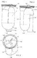
- FIGS. 1 to 6 a first embodiment of an inventive Absaugsiphons (Absauggeruchver gleiches) 1 is shown.
- the Absaugsiphon 1 is provided on its upper side with a in the drain opening of a drain basin, such as a urinal or wash basin, sealingly inserted plate 1.1, in which an inlet port 1.2 is formed.
- the plate 1.1 has at its peripheral edge on a seal holder 1.3.
- the seal holder 1.3 is formed for example by an annular groove 1.6, in which a sealing ring (not shown) can be used.
- the plate 1.1 is preferably formed circular disk-shaped.
- the collar 1.4 of the plate 1.1 defines a shell-like depression 1.7.
- a web-shaped projection 1.8 is formed as an assembly aid. This projection 1.8 can be taken eg with a pair of pliers.
- the inlet opening 1.2 is arranged eccentrically to the center M of the circular disk-shaped plate 1.1.
- the inlet opening 1.2 is spaced from the center M of the plate 1.1, wherein the edge of the inlet opening 1.2 can affect the center M (see. Fig. 8 ).
- a (first) substantially vertically to the plate 1.1 extending, vertically downwardly directed channel 1.9 is connected.
- an arcuate pipe part (channel part) 1.10 which represents a deflection, into a vertically upward channel 1.11 and from there into an arcuate deflection 1.12.
- the deflection edge 1.13 of the lower arcuate channel part 1.10 and the overflow edge 1.14 of the upper arcuate deflection 1.12 define the sealing water height H of the suction siphon 1.
- a third channel 1.15 whose lower end defines the outlet 1.16 of the siphoning siphon 1, adjoins the upper arcuate deflection 1.12 in the direction of flow.
- the defined by the third channel 1.15 outlet 1.16 ends in the installed state of Absaugsiphons 1 free.
- the outlet 1.16 or the end of the third channel 1.15 is thus not connected in the installed state of the Absaugsiphons 1 with a drain line such that between the outlet and drain line a closed connection is formed.
- the outlet 1.16 of the suction siphon is preferably lower than the arcuate tubular part 1.10, which represents the transition from the first channel 1.9 to the second channel 1.11.
- the end of the third channel 1.15 thus opens free-standing and protrudes downwards with respect to the curved tubular part 1.10.
- the flow cross-sectional area or the inner diameter of the third channel 1.15 is reduced compared to the second channel 1.11.
- the average flow cross sectional area of the third channel 1.15 is in the range of 0.65 to 0.7 times the average flow cross sectional area of the second channel 1.11.
- FIGS. 4 to 6 It can be seen that the compared in the second channel 1.11 narrowed flow cross-sectional area of the third channel 1.15 of the cross-sectional reduction 1.17, which is provided immediately after the arcuate deflection 1.12, to the outlet 1.16 of Absaugsiphons 1 extends.
- the Absaugsiphon 1 is constructed of a plurality of plastic injection molded parts, which are gas-tightly connected to each other by welding or gluing.
- the three mutually parallel channels 1.9, 1.11, 1.15 of Absaugsiphons 1 are preferably formed from circular cylindrical tubes.
- the third channel 1.15 is arranged offset radially relative to the second channel 1.11.
- the third channel 1.15 is arranged offset radially relative to the first channel 1.9.
- the lateral surfaces of the first channel 1.9 and the second channel 1.11 are preferably connected directly touching each other (see. Fig. 6 ).
- the lateral surfaces of the second channel 1.11 and the third channel 1.15 are spaced apart and by a bridge-like web 1.18 interconnected.
- the channels or pipes 1.9, 1.11, 1.15 of the Absaug siphon 1 are considered in cross section within a circular envelope 1.19, whose diameter is greater than the sum of the outer diameter of the first and second channels 1.9, 1.11, but smaller than the sum of the outer diameter of all three channels or tubes 1.9, 1.11, 1.15 (cf. Fig. 6 ).
- the inlet of the suction siphon 1 is formed by a funnel-like section 1.20, which merges into the first channel 1.9.
- the inlet opening 1.2 defines the upper end 1.21 of the funnel-like section 1.20.
- the vertical distance between the upper end of 1.21 and the lower, in the first channel 1.9 merging end of the funnel-like portion 1.20 1.20 is in the illustrated embodiment about a quarter to a third of the sealing water height H Absaugsiphons the first
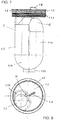
- Absaugsiphons 1 differs from that in the FIGS. 1 to 6 shown embodiment only in that the circular disk-shaped plate 1.1 is provided with an external thread 1.23, that is arranged below the seal holder 1.3.
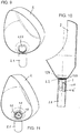
- FIGS. 9 to 14 different drainage basin 2, 3 or drainage channels 4 are shown, in which the Absaugsiphon 1 of the invention can be used.
- the Absaugsiphon 1 can be inserted from above into the drain opening of the respective drain basin 2, 3, 4 or screwed and removed upwards from the drain opening.
- FIGS. 9 to 11 show a urinal 2, in whose drain opening the Absaugsiphon 1 can be used sealingly with the plate 1.1.
- the drain opening of the urinal 2 or a drain pipe 2.1 fixed thereto has an annular shoulder 2.2, on which the plate 1.1 is placed, so that in the seal receptacle (1.3) arranged sealing ring radially sealing against the annular groove (1.6) of the plate 1.1 and against the inner circumference of paragraph 2.2 of the drain pipe 2.1 and the drain basin 2 is pressed (see. Figures 2 and 4 ).
- Fig. 10 It can be seen that the outlet end 1.16 'of the suction siphon 1 inserted into the drainage pipe 2.1 discharges free-standing, ie forms no closed connection with the drainage pipe 2.1.
- Absaugsiphons 1 is covered by a plate-shaped cover 1.24, whose bottom defines a water inlet gap 1.25 and which is releasably connected to the Absaugsiphon 1.
- Fig. 12 a section of a washbasin 3 is shown, the drain opening is provided with an internal thread 3.1, in which a Absaugsiphon 1 according to Fig. 7 is screwed sealingly.
- a Absaugsiphon 1 according to Fig. 7 is screwed sealingly.
- FIGS. 13 and 14 show a trough-shaped drainage basin 4, for example, a launder, whose drain opening according to the in Fig. 12 illustrated embodiment is provided with an internal thread 4.1, in which a Absaugsiphon 1 according to Fig. 7 is screwed sealingly.
- the cover 1.24 may also be designed such that it can be detachably connected to a pipe socket-shaped, an external thread having, attachable to the drain opening of the drain basin 2, 3 or 4 clamping part.
- the suction siphon 1 according to the invention or the circular disk-shaped plate 1.1 instead of an external thread 1.23 according to FIG Fig. 7 also be provided for example with a bayonet lock.
Landscapes
- Engineering & Computer Science (AREA)
- Health & Medical Sciences (AREA)
- Life Sciences & Earth Sciences (AREA)
- Hydrology & Water Resources (AREA)
- Public Health (AREA)
- Water Supply & Treatment (AREA)
- Environmental & Geological Engineering (AREA)
- Sanitary Device For Flush Toilet (AREA)
- Sink And Installation For Waste Water (AREA)
Description
- Die Erfindung betrifft eine Ablaufarmatur für ein Ablaufbecken, insbesondere Urinal oder Waschbecken, mit einem Absaugsiphon, der einen Geruchverschluss definiert und einen Einlass aufweist, der an eine Ablauföffnung des Ablaufbeckens anzuschließen ist, und der einen Auslass aufweist, wobei der Absaugsiphon von oben in die Ablauföffnung des Ablaufbeckens einsetzbar und nach oben aus dieser Ablauföffnung ausbaubar ist und abschnittsweise drei im Wesentlichen parallel zueinander verlaufende Kanäle aufweist, wobei durch den ersten der drei Kanäle in den Absaugsiphon eingetretene Flüssigkeit nach unten geführt werden kann, während durch den zweiten der drei Kanäle die von dem ersten Kanal nach unten geführte Flüssigkeit wieder nach oben geführt werden kann, und wobei von dem dritten Kanal die von dem zweiten Kanal nach oben geführte Flüssigkeit nach unten zu dem Auslass geführt werden kann, wobei der dritte Kanal eine gegenüber dem zweiten Kanal verengte Strömungsquerschnittsfläche aufweist, wobei die durchschnittliche Strömungsquerschnittsfläche des dritten Kanals zumindest entlang eines Höhenabschnitts, der mindestens das 0,5-fache der Sperrwasserhöhe des Geruchverschlusses beträgt, kleiner ist als die durchschnittliche Strömungsquerschnittsfläche des zweiten Kanals, und wobei der durch den dritten Kanal definierte Auslass im eingebauten Zustand des Absaugsiphons frei endet.
- Aus der
EP 1 837 447 B1 ist ein Urinal mit einer eine auswechselbare Geruchverschlusseinheit aufweisenden Ablaufvorrichtung bekannt. Die Geruchverschlusseinheit ist derart ausgebildet, dass sie von oben durch die Ablauföffnung des Urinals in die Ablaufvorrichtung eingebracht werden kann. Die Geruchverschlusseinheit weist dabei eine zylindrische Außenkontur auf, deren Zylinderachse sich im eingebauten Zustand der Geruchverschlusseinheit im Wesentlichen vertikal erstreckt. Ferner weist die Geruchverschlusseinheit abschnittsweise drei parallel zueinander verlaufende Kanäle auf, wobei durch den ersten der drei Kanäle in die Geruchverschlusseinheit eingetretene Flüssigkeit nach unten geführt werden kann. Durch den zweiten der drei Kanäle kann die von dem ersten Kanal nach unten geführte Flüssigkeit dann wieder nach oben geführt werden, während schließlich von dem dritten Kanal die von dem zweiten Kanal nach oben geführte Flüssigkeit nach unten geführt werden kann, so dass sie aus der Geruchverschlusseinheit heraustreten kann. Diese bekannte Geruchverschlusseinheit ist so ausgebildet, dass sie im Wesentlichen nur nach dem Verdrängungsprinzip arbeitet, d.h. eine in die Geruchverschlusseinheit eintretende Flüssigkeitsmenge verdrängt eine entsprechende Flüssigkeitsmenge aus der Geruchverschlusseinheit. - Weiterhin ist aus der
EP 1 335 076 B1 eine insbesondere für Urinale bestimmte Ablaufarmatur mit einem auswechselbaren Absaugsiphon bekannt. Der Absaugsiphon weist einen Einlass auf, der an eine Ablauföffnung eines Urinals bzw. Sanitärkörpers anzuschließen ist. Ferner weist der Absaugsiphon einen Auslass auf, welcher mit einer Ablaufleitung, zur Bildung einer geschlossenen Verbindung zwischen dem Auslass und der Ablaufleitung zu verbinden ist, wobei der Auslass nach unten ragt und steckbar ist. Der Absaugsiphon ist von oben in die Ablauföffnung des Sanitärkörpers einsetzbar und nach oben aus dieser Ablauföffnung ausbaubar. Zur Herstellung der Steckverbindung zwischen Auslass und Ablaufleitung muss dieser Absaugsiphon lagerichtig in die Ablauföffnung des Sanitärkörpers eingesetzt werden. Der Absaugsiphon kommuniziert dabei mit einem Sumpf, der durch einen Ablaufbogen der Ablaufleitung definiert ist. - Die
JP-A-2011 94473 US 172 865 A offenbart eine Ablaufarmatur nach dem Oberbegriff des Anspruchs 1. - Der vorliegenden Erfindung liegt die Aufgabe zugrunde, eine Ablaufgarnitur der eingangs genannten Art zu schaffen, bei welcher der Wasseraustausch im Geruchverschluss schon mit einer relativ kleinen Flüssigkeitsmenge bei geringem Flüssigkeitszulauf stattfinden soll und dabei auch gegebenenfalls Schwimmstoffe abgeführt werden müssen, und bei welcher der Absaugsiphon in die Ablauföffnung des Ablaufbeckens weitgehend drehlagenunabhängig hinsichtlich der durch die Ablauföffnung verlaufenden vertikalen Mittelachse dichtend eingesetzt werden kann.
- Zur Lösung dieser Aufgabe wird eine Ablaufarmatur mit den Merkmalen des Anspruchs 1 vorgeschlagen.
- Die erfindungsgemäße Ablaufarmatur bzw. ihr Absaugsiphon ist dadurch gekennzeichnet, dass die durchschnittliche Strömungsquerschnittsfläche des dritten Kanals des Absaugsiphons im Bereich des 0,6-fachen bis 0,85-fachen der durchschnittlichen Strömungsquerschnittsfläche des zweiten Kanals liegt, wobei der Auslass des Absaugsiphons tiefer liegt als ein bogenförmiger Rohrteil, der den Übergang vom ersten Kanal zum zweiten Kanal definiert, und wobei der Längenabschnitt des dritten Kanals, der die gegenüber dem zweiten Kanal verengte Strömungsquerschnittsfläche aufweist, geradlinig bis zum Auslass des Absaugsiphons ausgebildet ist.
- Durch die Verengung des dritten Kanals wird erreicht, dass in dem Absaugsiphon ein Wasseraustausch schon bei relativ geringem Spülvolumen stattfindet und auch Schwimmstoff mit abgeführt werden. Außerdem kann der erfindungsgemäße Absaugsiphon weitgehend drehlagenunabhängig in die Ablauföffnung des Ablaufbeckens dichtend eingesetzt werden, da er für seine Funktion die Herstellung einer geschlossenen Verbindung zwischen Siphonauslass und Ablaufleitung nicht erfordert.
- Die erfindungsgemäße Ablaufarmatur bzw. der erfindungsgemäße Absaugsiphon kann in unterschiedliche Ablaufbecken eingesetzt werden, insbesondere in sanitäre Ablaufbecken wie Urinale, Urinalrinnen, Waschbecken, Waschrinnen und Duschen, aber auch in industrielle Ablaufbecken und Ablaufrinnen, z.B. in Spülbecken industrieller Betriebe oder in Wasserablaufrinnen von Waschstrassen. Die erfindungsgemäße Ablaufarmatur bzw. der erfindungsgemäße Absaugsiphon ist somit grundsätzlich universell einsetzbar.
- Durch das Merkmal der erfindungsgemäßen Ablaufarmatur, wonach die durchschnittliche Strömungsquerschnittsfläche des dritten Kanals des Absaugsiphons im Bereich des 0,6-fachen bis 0,85-fachen der durchschnittlichen Strömungsquerschnittsfläche des zweiten Kanals liegt, kann der Wasseraustausch in dem Geruchverschluss bei relativ geringem Spülvolumen besonders zuverlässig sichergestellt werden.
- Hinsichtlich des Wasseraustausches im Geruchverschluss bei relativ geringem Spülvolumen sowie hinsichtlich des Mitabführens von Schwimmstoffen ist es von Vorteil, dass der Auslass des Absaugsiphons erfindungsgemäß tiefer liegt als ein bogenförmiger Rohrteil, der den Übergang vom ersten Kanal zum zweiten Kanal definiert.
- Ferner ist es in fertigungstechnischer Hinsicht von Vorteil, dass der Längenabschnitt des dritten Kanals, der die gegenüber dem zweiten Kanal verengte Strömungsquerschnittsfläche aufweist, geradlinig bis zum Auslass des Absaugsiphons ausgebildet ist. Vorzugsweise können die drei parallel zueinander verlaufenden Kanäle des Absaugsiphons aus kreiszylindrischen Rohren gebildet werden.
- Eine bevorzugte Ausgestaltung der Erfindung ist dadurch gekennzeichnet, dass sich die gegenüber dem zweiten Kanal verengte Strömungsquerschnittsfläche des dritten Kanals bis zum Auslass des Absaugsiphons erstreckt. Diese Ausgestaltung ermöglicht bei kompakter Bauform des Absaugsiphons den Wasseraustausch im Geruchverschluss bei relativ geringem Spülvolumen.
- Eine weitere bevorzugte Ausgestaltung der Erfindung sieht vor, dass der Einlass des Absaugsiphons durch einen trichterartigen Abschnitt gebildet ist, der in den ersten Kanal übergeht, wobei der Höhenabstand zwischen dem oberen Ende und dem unteren, in den ersten Kanal übergehenden Ende des trichterartigen Abschnitts mindestens 15%, vorzugsweise mindestens 25% der Sperrwasserhöhe des Absaugsiphons beträgt. Diese Ausgestaltung begünstigt einen raschen Flüssigkeitsablauf sowie den Wasseraustausch im Geruchverschluss bei relativ geringem Spülvolumen.
- Hinsichtlich einer kompakten Bauform des Absaugsiphons ist es ferner von Vorteil, wenn gemäß einer weiteren bevorzugten Ausgestaltung der Erfindung der Absaugsiphon mit einer eine Einlassöffnung aufweisenden kreisscheibenförmigen Platte versehen ist, deren Umfangskante eine Dichtungsaufnahme aufweist, wobei die Einlassöffnung exzentrisch, vorzugsweise beabstandet vom Mittelpunkt der kreisscheibenförmigen Platte angeordnet ist.
- Um eine besonders sichere Festlegung des Absaugsiphons in dem jeweiligen Ablaufbecken zu erzielen, sieht eine weitere vorteilhafte Ausgestaltung der Erfindung vor, dass die kreisscheibenförmige Platte unterhalb der Dichtungsaufnahme ein Außengewinde aufweist. Der Absaugsiphon lässt sich somit besonders zuverlässig an einer mit einem Innengewinde versehenen Ablauföffnung eines Ablaufbeckens dichtend festlegen.
- Um den Ein- sowie Ausbau des erfindungsgemäßen Absaugsiphons zu erleichtern, sieht eine weitere vorteilhafte Ausgestaltung der Erfindung vor, dass die kreisscheibenförmige Platte auf ihrer Oberseite mindestens einen zapfen- oder stegförmigen Vorsprung als Montagehilfe aufweist.
- Insbesondere aus ästhetischen Gründen sieht eine weitere bevorzugte Ausgestaltung der Erfindung vor, dass der Einlass des Absaugsiphons durch eine tellerförmige Abdeckung verdeckt ist, deren Unterseite einen Wassereinlaufspalt begrenzt und die lösbar mit dem Absaugsiphon und/oder mit einem rohrstutzenförmigen, ein Außengewinde aufweisenden, an der Ablauföffnung des Ablaufbeckens festlegbaren Klemmteil verbindbar ist. Die Abdeckung kann zudem das Eindringen von unlöslichen und/oder groben Gegenständen, z.B. von Zigarettenfiltern, Schrauben und anderen Metallteilen, in den Absaugsiphon verhindern.
- Weitere bevorzugte und vorteilhafte Ausgestaltungen der erfindungsgemäßen Ablaufarmatur bzw. des erfindungsgemäßen Absaugsiphons sind in den Unteransprüchen angegeben.
- Nachfolgend wird die Erfindung anhand einer mehrere Ausführungsbeispiele darstellenden Zeichnung näher erläutert. Es zeigen:
- Fig. 1
- ein erstes Ausführungsbeispiel eines erfindungsgemäßen Absaugsiphons, in einer perspektivischen Seitenansicht;
- Fig. 2
- der Absaugsiphon der
Fig. 1 , in einer anderen perspektivischen Seitenansicht; - Fig. 3
- der Absaugsiphon der
Fig. 1 , in einer perspektivischen Draufsicht; - Fig. 4
- der Absaugsiphon der
Fig. 1 , in einer Seitenansicht; - Fig. 5
- der Absaugsiphon der
Fig. 1 , in einer Vertikalschnittansicht entlang der Schnittlinie V-V derFig. 4 ; - Fig. 6
- der Absaugsiphon der
Fig. 1 , in einer Horizontalschnittansicht entlang der Schnittlinie VI-VI derFig. 4 ; - Fig. 7
- ein zweites Ausführungsbeispiel eines erfindungsgemäßen Absaugsiphons, in Seitenansicht;
- Fig. 8
- der Absaugsiphon der
Fig. 7 , in Draufsicht; - Fig. 9 bis Fig. 11
- ein Urinal mit einem erfindungsgemäßen Absaugsiphon gemäß
Fig. 1 , in perspektivischen Schnittansichten bzw. in einer Vertikalschnittansicht; - Fig. 12
- ein Abschnitt eines Waschbeckens, in Vertikalschnittansicht, mit einem erfindungsgemäßen Absaugsiphon gemäß
Fig. 7 ; und - Fig. 13 und Fig. 14
- ein rinnenförmiges Ablaufbecken mit einem erfindungsgemäßen Absaugsiphon gemäß
Fig. 7 , in einer perspektivischen Draufsicht bzw. einer Vertikalschnittansicht. - In den
Figuren 1 bis 6 ist ein erstes Ausführungsbeispiel eines erfindungsgemäßen Absaugsiphons (Absauggeruchverschlusses) 1 dargestellt. Der Absaugsiphon 1 ist an seiner Oberseite mit einer in die Ablauföffnung eines Ablaufbeckens, beispielsweise eines Urinals oder Waschbeckens, dichtend einzusetzenden Platte 1.1 versehen, in der eine Einlassöffnung 1.2 ausgebildet ist. Die Platte 1.1 weist an ihrer Umfangskante eine Dichtungsaufnahme 1.3 auf. Die Dichtungsaufnahme 1.3 ist beispielsweise durch eine Ringnut 1.6 gebildet, in die ein Dichtungsring (nicht gezeigt) eingesetzt werden kann. Die Platte 1.1 ist vorzugsweise kreisscheibenförmig ausgebildet. Sie weist vorzugsweise einen nach oben vorstehenden, ringförmig geschlossenen Kragen 1.4 auf, an dem radial nach außen vorstehende, ringförmige Rippen 1.5 angeformt sind, welche eine Ringnut 1.6 begrenzen. Der Kragen 1.4 der Platte 1.1 definiert eine schalenartige Vertiefung 1.7. An der Oberseite der Platte 1.1 bzw. am Boden der Vertiefung 1.7 ist ein stegförmiger Vorsprung 1.8 als Montagehilfe angeformt. Dieser Vorsprung 1.8 kann z.B. mit einer Zange gefasst werden. - Die Einlassöffnung 1.2 ist exzentrisch zum Mittelpunkt M der kreisscheibenförmigen Platte 1.1 angeordnet. Vorzugsweise liegt die Einlassöffnung 1.2 beabstandet vom Mittelpunkt M der Platte 1.1, wobei der Rand der Einlassöffnung 1.2 den Mittelpunkt M tangieren kann (vgl.
Fig. 8 ). - An die Einlassöffnung 1.2 ist ein (erster) im Wesentlichen senkrecht zu der Platte 1.1 verlaufender, vertikal abwärtsgerichteter Kanal 1.9 angeschlossen. Von dem Kanal 1.9 führt ein bogenförmiger Rohrteil (Kanalteil) 1.10, der eine Umlenkung darstellt, in einen vertikal aufwärtsgerichteten Kanal 1.11 und von dort in eine bogenförmige Umlenkung 1.12. Die Umlenkkante 1.13 des unteren bogenförmigen Kanalteils 1.10 und die Überlaufkante 1.14 der oberen bogenförmigen Umlenkung 1.12 definieren die Sperrwasserhöhe H des Absaugsiphons 1.
- An die obere bogenförmige Umlenkung 1.12 schließt sich in Fließrichtung ein dritter Kanal 1.15 an, dessen unteres Ende den Auslass 1.16 des Absaugsiphons 1 definiert. Der durch den dritten Kanal 1.15 definierte Auslass 1.16 endet im eingebauten Zustand des Absaugsiphons 1 frei. Der Auslass 1.16 bzw. das Ende des dritten Kanals 1.15 ist im montierten Zustand des Absaugsiphons 1 also nicht mit einer Ablaufleitung derart verbunden, dass zwischen Auslass und Ablaufleitung eine geschlossene Verbindung gebildet ist.
- Der Auslass 1.16 des Absaugsiphons liegt vorzugsweise tiefer als der bogenförmige Rohrteil 1.10, der den Übergang vom ersten Kanal 1.9 zum zweiten Kanal 1.11 darstellt. Das Ende des dritten Kanals 1.15 mündet somit freikragend und steht gegenüber dem bogenförmigen Rohrteil 1.10 nach unten vor.
- Die Strömungsquerschnittsfläche bzw. der Innendurchmesser des dritten Kanals 1.15 ist im Vergleich zu dem zweiten Kanal 1.11 reduziert. In dem dargestellten Ausführungsbeispiel liegt die durchschnittliche Strömungsquerschnittsfläche des dritten Kanals 1.15 im Bereich des 0,65-fachen bis 0,7-fachen der durchschnittlichen Strömungsquerschnittsfläche des zweiten Kanals 1.11. Insbesondere in den
Figuren 4 bis 6 ist zu erkennen, dass sich die im Vergleich zu dem zweiten Kanal 1.11 verengte Strömungsquerschnittsfläche des dritten Kanals 1.15 von der Querschnittsreduzierung 1.17, die unmittelbar nach der bogenförmigen Umlenkung 1.12 vorgesehen ist, bis zum Auslass 1.16 des Absaugsiphons 1 erstreckt. - Der Absaugsiphon 1 ist aus mehreren Kunststoff-Spritzgießteilen aufgebaut, die miteinander durch Schweißen oder Kleben gasdicht verbunden sind. Die drei parallel zueinander verlaufenden Kanäle 1.9, 1.11, 1.15 des Absaugsiphons 1 sind dabei vorzugsweise aus kreiszylindrischen Rohren gebildet. Dabei ist der dritte Kanal 1.15 gegenüber dem zweiten Kanal 1.11 radial versetzt angeordnet. Ferner ist der dritte Kanal 1.15 auch gegenüber dem ersten Kanal 1.9 radial versetzt angeordnet. Die Mantelflächen des ersten Kanals 1.9 und des zweiten Kanals 1.11 sind vorzugsweise unmittelbar einander berührend miteinander verbunden (vgl.
Fig. 6 ). Die Mantelflächen des zweiten Kanals 1.11 und des dritten Kanals 1.15 sind dagegen beabstandet und durch einen brückenartigen Steg 1.18 miteinander verbunden. Die Kanäle bzw. Rohre 1.9, 1.11, 1.15 des Absaugsiphons 1 liegen im Querschnitt betrachtet innerhalb einer kreisförmigen Umhüllenden 1.19, deren Durchmesser größer ist als die Summe der Außendurchmesser des ersten und zweiten Kanals 1.9, 1.11, aber kleiner ist als die Summe der Außendurchmesser aller drei Kanäle bzw. Rohre 1.9, 1.11, 1.15 (vgl.Fig. 6 ). - Der Einlass des Absaugsiphons 1 ist durch einen trichterartigen Abschnitt 1.20 gebildet, der in den ersten Kanal 1.9 übergeht. Die Einlassöffnung 1.2 definiert das obere Ende 1.21 des trichterartigen Abschnitts 1.20. Der Höhenabstand zwischen dem oberen Ende 1.21 und dem unteren, in den ersten Kanal 1.9 übergehenden Ende 1.22 des trichterartigen Abschnitts 1.20 beträgt in dem dargestellten Ausführungsbeispiel etwa ein Viertel bis ein Drittel der Sperrwasserhöhe H des Absaugsiphons 1.
- Das in den
Figuren 7 und 8 dargestellte Ausführungsbeispiel des erfindungsgemäßen Absaugsiphons 1 unterscheidet sich von dem in denFiguren 1 bis 6 gezeigten Ausführungsbeispiel lediglich dadurch, dass die kreisscheibenförmige Platte 1.1 mit einem Außengewinde 1.23 versehen ist, dass unterhalb der Dichtungsaufnahme 1.3 angeordnet ist. - In den
Figuren 9 bis 14 sind verschiedene Ablaufbecken 2, 3 bzw. Ablaufrinnen 4 dargestellt, in die der erfindungsgemäße Absaugsiphon 1 eingesetzt werden kann. Der Absaugsiphon 1 kann dabei von oben in die Ablauföffnung des jeweiligen Ablaufbeckens 2, 3, 4 eingesetzt bzw. eingeschraubt und nach oben aus der Ablauföffnung ausgebaut werden. - Die
Figuren 9 bis 11 zeigen ein Urinal 2, in dessen Ablauföffnung der Absaugsiphon 1 mit der Platte 1.1 dichtend eingesetzt werden kann. Die Ablauföffnung des Urinals 2 oder ein daran festgelegtes Ablaufrohr 2.1 weist einen ringförmigen Absatz 2.2 auf, auf dem die Platte 1.1 aufgesetzt wird, so dass der in der Dichtungsaufnahme (1.3) angeordnete Dichtungsring radial dichtend gegen die Ringnut (1.6) der Platte 1.1 sowie gegen den Innenumfang des Absatzes 2.2 des Ablaufrohres 2.1 bzw. des Ablaufbeckens 2 gepresst ist (vgl.Figuren 2 und4 ). InFig. 10 ist zu erkennen, dass das Auslassende 1.16' des in das Ablaufrohr 2.1 eingesetzten Absaugsiphons 1 freikragend mündet, also mit dem Ablaufrohr 2.1 keine geschlossene Verbindung bildet. - Des Weiteren ist der Einlass des Absaugsiphons 1 durch eine tellerförmige Abdeckung 1.24 verdeckt, deren Unterseite einen Wassereinlaufspalt 1.25 begrenzt und die lösbar mit dem Absaugsiphon 1 verbindbar ist.
- In
Fig. 12 ist ein Abschnitt eines Waschbeckens 3 dargestellt, dessen Ablauföffnung mit einem Innengewinde 3.1 versehen ist, in das ein Absaugsiphon 1 gemäßFig. 7 dichtend eingeschraubt ist. An der die Dichtungsaufnahme 1.3 aufweisenden Platte 1.1 des Absaugsiphons 1 ist wiederum eine tellerförmige Abdeckung 1.24 lösbar befestigt, deren Unterseite einen Wassereinlaufspalt 1.25 begrenzt. - Die
Figuren 13 und 14 zeigen ein rinnenförmiges Ablaufbecken 4, beispielsweise eine Waschrinne, dessen/deren Ablauföffnung entsprechend dem inFig. 12 dargestellten Ausführungsbeispiel mit einem Innengewinde 4.1 versehen ist, in das ein Absaugsiphon 1 gemäßFig. 7 dichtend eingeschraubt ist. - Die Ausführung der vorliegenden Erfindung ist nicht auf die in der Zeichnung dargestellten Ausführungsbeispiele beschränkt. Vielmehr sind zahlreiche Varianten möglich, die auch bei gegenüber den gezeigten Ausführungsbeispielen abgewandelter Gestaltung von der in den beiliegenden Ansprüchen angegebenen Erfindung Gebrauch machen. So kann beispielsweise die Abdeckung 1.24 auch derart ausgebildet sein, dass sie lösbar mit einem rohrstutzenförmigen, ein Außengewinde aufweisenden, an der Ablauföffnung des Ablaufbeckens 2, 3 oder 4 festlegbaren Klemmteil verbindbar ist. Des Weiteren kann der erfindungsgemäße Absaugsiphon 1 bzw. die kreisscheibenförmige Platte 1.1 anstelle eines Außengewindes 1.23 gemäß
Fig. 7 auch beispielsweise mit einem Bajonettverschluss versehen sein.
Claims (10)
- Ablaufarmatur für ein Ablaufbecken (2, 3, 4), insbesondere Urinal oder Waschbecken, mit einem Absaugsiphon (1), der einen Geruchverschluss definiert und einen Einlass (1.2) aufweist, der an eine Ablauföffnung des Ablaufbeckens anzuschließen ist, und der einen Auslass (1.16) aufweist, wobei der Absaugsiphon (1) von oben in die Ablauföffnung des Ablaufbeckens (2, 3, 4) einsetzbar und nach oben aus dieser Ablauföffnung ausbaubar ist und abschnittsweise drei im Wesentlichen parallel zueinander verlaufende Kanäle (1.9, 1.11, 1.15) aufweist, wobei durch den ersten (1.9) der drei Kanäle in den Absaugsiphon eingetretene Flüssigkeit nach unten geführt werden kann, während durch den zweiten (1.11) der drei Kanäle die von dem ersten Kanal (1.9) nach unten geführte Flüssigkeit wieder nach oben geführt werden kann, und wobei von dem dritten Kanal (1.15) die von dem zweiten Kanal (1.11) nach oben geführte Flüssigkeit nach unten zu dem Auslass (1.16) geführt werden kann, wobei der dritte Kanal (1.15) eine gegenüber dem zweiten Kanal (1.11) verengte Strömungsquerschnittsfläche aufweist, wobei die durchschnittliche Strömungsquerschnittsfläche des dritten Kanals (1.15) zumindest entlang eines Höhenabschnitts, der mindestens das 0,5-fache der Sperrwasserhöhe (H) des Geruchverschlusses beträgt, kleiner ist als die durchschnittliche Strömungsquerschnittsfläche des zweiten Kanals (1.11), und wobei der durch den dritten Kanal (1.15) definierte Auslass (1.16) im eingebauten Zustand des Absaugsiphons (1) frei endet, wobei der Auslass (1.16) des Absaugsiphons (1) tiefer liegt als ein bogenförmiger Rohrteil (1.10), der den Übergang vom ersten Kanal (1.9) zum zweiten Kanal (1.11) definiert, dadurch gekennzeichnet, dass die durchschnittliche Strömungsquerschnittsfläche des dritten Kanals (1.15) im Bereich des 0,6-fachen bis 0,85-fachen der durchschnittlichen Strömungsquerschnittsfläche des zweiten Kanals (1.11) liegt, wobei der Längenabschnitt des dritten Kanals (1.15), der die gegenüber dem zweiten Kanal (1.11) verengte Strömungsquerschnittsfläche aufweist, geradlinig bis zum Auslass (1.16) des Absaugsiphons ausgebildet ist.
- Ablaufarmatur nach Anspruch 1, dadurch gekennzeichnet, dass sich die gegenüber dem zweiten Kanal (1.11) verengte Strömungsquerschnittsfläche des dritten Kanals (1.15) bis zum Auslass (1.16) des Absaugsiphons erstreckt.
- Ablaufarmatur nach Anspruch 1 oder 2, dadurch gekennzeichnet, dass der Einlass des Absaugsiphons durch einen trichterartigen Abschnitt (1.20) gebildet ist, der in den ersten Kanal (1.9) übergeht, wobei der Höhenabstand zwischen dem oberen Ende (1.21) und dem unteren, in den ersten Kanal übergehenden Ende (1.22) des trichterartigen Abschnitts (1.20) mindestens 15%, vorzugsweise mindestens 25% der Sperrwasserhöhe (H) des Absaugsiphons beträgt.
- Ablaufarmatur nach einem der Ansprüche 1 bis 3, dadurch gekennzeichnet, dass der Absaugsiphon (1) mit einer eine Einlassöffnung (1.2) aufweisenden kreisscheibenförmigen Platte (1.1) versehen ist, deren Umfangskante eine Dichtungsaufnahme (1.3) aufweist, wobei die Einlassöffnung (1.2) exzentrisch, vorzugsweise beabstandet vom Mittelpunkt (M) der kreisscheibenförmigen Platte (1.1) angeordnet ist.
- Ablaufarmatur nach den Ansprüchen 3 und 4, dadurch gekennzeichnet, dass die Einlassöffnung (1.2) das obere Ende (1.21) des trichterartigen Abschnitts (1.20) definiert.
- Ablaufarmatur nach Anspruch 4 oder 5, dadurch gekennzeichnet, dass die kreisscheibenförmige Platte (1.1) unterhalb der Dichtungsaufnahme (1.3) ein Außengewinde (1.23) aufweist.
- Ablaufarmatur nach einem der Ansprüche 4 bis 6, dadurch gekennzeichnet, dass die kreisscheibenförmige Platte (1.1) auf ihrer Oberseite mindestens einen zapfen- oder stegförmigen Vorsprung (1.8) als Montagehilfe aufweist.
- Ablaufarmatur nach einem der Ansprüche 1 bis 7, dadurch gekennzeichnet, dass die drei parallel zueinander verlaufenden Kanäle (1.9, 1.11, 1.15) des Absaugsiphons (1) aus kreiszylindrischen Rohren gebildet sind.
- Ablaufarmatur nach einem der Ansprüche 1 bis 8, dadurch gekennzeichnet, dass der dritte Kanal (1.15) zumindest gegenüber dem zweiten Kanal (1.11) radial versetzt angeordnet ist.
- Ablaufarmatur nach einem der Ansprüche 1 bis 9, dadurch gekennzeichnet, dass der Einlass des Absaugsiphons durch eine tellerförmige Abdeckung (1.24) verdeckt ist, deren Unterseite einen Wassereinlaufspalt (1.25) begrenzt und die lösbar mit dem Absaugsiphon (1) und/oder mit einem rohrstutzenförmigen, ein Außengewinde aufweisenden, an der Ablauföffnung des Ablaufbeckens festlegbaren Klemmteil verbindbar ist.
Priority Applications (1)
| Application Number | Priority Date | Filing Date | Title |
|---|---|---|---|
| PL13158875T PL2664721T3 (pl) | 2012-05-18 | 2013-03-13 | Armatura odpływowa do basenu odpływowego, w szczególności do pisuaru, z syfonem odsysającym |
Applications Claiming Priority (1)
| Application Number | Priority Date | Filing Date | Title |
|---|---|---|---|
| DE102012104325A DE102012104325B3 (de) | 2012-05-18 | 2012-05-18 | Ablaufarmatur für ein Ablaufbecken, insbesondere Urinal, mit einem Absaugsiphon |
Publications (3)
| Publication Number | Publication Date |
|---|---|
| EP2664721A2 EP2664721A2 (de) | 2013-11-20 |
| EP2664721A3 EP2664721A3 (de) | 2015-01-21 |
| EP2664721B1 true EP2664721B1 (de) | 2018-09-05 |
Family
ID=47877887
Family Applications (1)
| Application Number | Title | Priority Date | Filing Date |
|---|---|---|---|
| EP13158875.8A Active EP2664721B1 (de) | 2012-05-18 | 2013-03-13 | Ablaufarmatur für ein ablaufbecken, insbesondere urinal, mit einem absaugsiphon |
Country Status (4)
| Country | Link |
|---|---|
| EP (1) | EP2664721B1 (de) |
| DE (1) | DE102012104325B3 (de) |
| ES (1) | ES2692189T3 (de) |
| PL (1) | PL2664721T3 (de) |
Citations (1)
| Publication number | Priority date | Publication date | Assignee | Title |
|---|---|---|---|---|
| DE318264C (de) * |
Family Cites Families (9)
| Publication number | Priority date | Publication date | Assignee | Title |
|---|---|---|---|---|
| US172865A (en) * | 1876-02-01 | Improvement in stench-traps | ||
| FR732502A (fr) * | 1931-03-02 | 1932-09-21 | Perfectionnements apportés aux bondes siphoïdes pour éviers, postes d'eau, lavabos ou semblables | |
| DE2447695C3 (de) * | 1974-10-07 | 1978-10-12 | Fa. Franz Viegener Ii, 5952 Attendorn | Absaugvorrichtung mit Geruchverschluß für Urinale |
| DE4227574A1 (de) * | 1992-08-20 | 1994-02-24 | Wella Ag | Siphon |
| IL139365A (en) * | 1998-05-05 | 2004-06-20 | Keller Hans | Stink trap for a variable |
| EP1335076B1 (de) * | 2002-02-11 | 2005-06-01 | Geberit Technik Ag | Ablaufarmatur für eine Sanitärvorrichtung, insbesondere Urinal |
| EP1574629B1 (de) * | 2004-03-12 | 2010-05-12 | Geberit International AG | Ablaufarmatur für eine sanitäre Apparatur, insbesondere Duschwanne |
| ATE509163T1 (de) * | 2006-03-25 | 2011-05-15 | Dallmer Gmbh & Co Kg | Urinal |
| JP5700484B2 (ja) * | 2009-09-29 | 2015-04-15 | 株式会社Lixil | 小便器用排水トラップ |
-
2012
- 2012-05-18 DE DE102012104325A patent/DE102012104325B3/de active Active
-
2013
- 2013-03-13 EP EP13158875.8A patent/EP2664721B1/de active Active
- 2013-03-13 ES ES13158875.8T patent/ES2692189T3/es active Active
- 2013-03-13 PL PL13158875T patent/PL2664721T3/pl unknown
Patent Citations (1)
| Publication number | Priority date | Publication date | Assignee | Title |
|---|---|---|---|---|
| DE318264C (de) * |
Also Published As
| Publication number | Publication date |
|---|---|
| PL2664721T3 (pl) | 2018-12-31 |
| ES2692189T3 (es) | 2018-11-30 |
| EP2664721A2 (de) | 2013-11-20 |
| DE102012104325B3 (de) | 2013-11-21 |
| EP2664721A3 (de) | 2015-01-21 |
Similar Documents
| Publication | Publication Date | Title |
|---|---|---|
| EP2045403B1 (de) | Ablaufgarnitur mit integriertem Überlauf | |
| EP2363543B1 (de) | Ablaufgarnitur mit Reinigungsöffnung | |
| EP2453065A2 (de) | Ablaufgarnitur mit verdeckt positionierbarem Überlauf | |
| EP2426283A2 (de) | Mehrzweck-Siphon | |
| EP1288379A1 (de) | Ablauf für ein Waschbecken mit einem schlitzförmigen Auslauf | |
| EP2711475B1 (de) | Spüle mit einer belüfteten Ablaufeinrichtung | |
| EP1335076B1 (de) | Ablaufarmatur für eine Sanitärvorrichtung, insbesondere Urinal | |
| DE102008038274B3 (de) | Ablauf | |
| DE202008011010U1 (de) | Ablauf | |
| DE19741827B4 (de) | Ablaufarmatur für Bade- oder Duschwannen | |
| EP2014840A2 (de) | Ablaufgarnitur für Duschen oder Badewannen | |
| EP2258905B1 (de) | Ablauf, insbesondere für sanitäre Einrichtungen | |
| EP2808458A1 (de) | Wasserablaufvorrichtung für eine Dusche und Duschbodenelement | |
| EP1862602B1 (de) | Becken mit verdecktem Überlauf und zugehöriger Ablaufgarnitur | |
| EP1447485A2 (de) | Ablaufeinrichtung | |
| EP2664721B1 (de) | Ablaufarmatur für ein ablaufbecken, insbesondere urinal, mit einem absaugsiphon | |
| DE10360310A1 (de) | Ablaufvorrichtung | |
| DE10201347A1 (de) | Einlaufvorrichtung für die Abführung von Regenwasser von einem Dach | |
| DE102010044940B4 (de) | Abwasserablauf mit Geruchsverschluss | |
| WO2005111326A1 (de) | Geruchsverschluss | |
| DE10204683B4 (de) | Becken | |
| EP2434063B1 (de) | Abwasserablauf mit Geruchsverschluss, insbesondere als Ablauf für Duschwannen | |
| EP1775395A1 (de) | Ablaufarmatur für sanitäre Anlagen | |
| DE2522425A1 (de) | Geruchverschluss fuer abwasserbehaelter | |
| EP3567169B1 (de) | Ablaufgarnitur |
Legal Events
| Date | Code | Title | Description |
|---|---|---|---|
| PUAI | Public reference made under article 153(3) epc to a published international application that has entered the european phase |
Free format text: ORIGINAL CODE: 0009012 |
|
| AK | Designated contracting states |
Kind code of ref document: A2 Designated state(s): AL AT BE BG CH CY CZ DE DK EE ES FI FR GB GR HR HU IE IS IT LI LT LU LV MC MK MT NL NO PL PT RO RS SE SI SK SM TR |
|
| AX | Request for extension of the european patent |
Extension state: BA ME |
|
| PUAL | Search report despatched |
Free format text: ORIGINAL CODE: 0009013 |
|
| AK | Designated contracting states |
Kind code of ref document: A3 Designated state(s): AL AT BE BG CH CY CZ DE DK EE ES FI FR GB GR HR HU IE IS IT LI LT LU LV MC MK MT NL NO PL PT RO RS SE SI SK SM TR |
|
| AX | Request for extension of the european patent |
Extension state: BA ME |
|
| RIC1 | Information provided on ipc code assigned before grant |
Ipc: E03C 1/29 20060101ALI20141216BHEP Ipc: E03C 1/284 20060101ALI20141216BHEP Ipc: E03D 13/00 20060101AFI20141216BHEP |
|
| 17P | Request for examination filed |
Effective date: 20150224 |
|
| RBV | Designated contracting states (corrected) |
Designated state(s): AL AT BE BG CH CY CZ DE DK EE ES FI FR GB GR HR HU IE IS IT LI LT LU LV MC MK MT NL NO PL PT RO RS SE SI SK SM TR |
|
| RAP1 | Party data changed (applicant data changed or rights of an application transferred) |
Owner name: VIEGA GMBH & CO. KG |
|
| STAA | Information on the status of an ep patent application or granted ep patent |
Free format text: STATUS: EXAMINATION IS IN PROGRESS |
|
| 17Q | First examination report despatched |
Effective date: 20161024 |
|
| RAP1 | Party data changed (applicant data changed or rights of an application transferred) |
Owner name: VIEGA TECHNOLOGY GMBH & CO. KG |
|
| GRAP | Despatch of communication of intention to grant a patent |
Free format text: ORIGINAL CODE: EPIDOSNIGR1 |
|
| STAA | Information on the status of an ep patent application or granted ep patent |
Free format text: STATUS: GRANT OF PATENT IS INTENDED |
|
| INTG | Intention to grant announced |
Effective date: 20180405 |
|
| GRAJ | Information related to disapproval of communication of intention to grant by the applicant or resumption of examination proceedings by the epo deleted |
Free format text: ORIGINAL CODE: EPIDOSDIGR1 |
|
| STAA | Information on the status of an ep patent application or granted ep patent |
Free format text: STATUS: EXAMINATION IS IN PROGRESS |
|
| GRAP | Despatch of communication of intention to grant a patent |
Free format text: ORIGINAL CODE: EPIDOSNIGR1 |
|
| STAA | Information on the status of an ep patent application or granted ep patent |
Free format text: STATUS: GRANT OF PATENT IS INTENDED |
|
| INTC | Intention to grant announced (deleted) | ||
| INTG | Intention to grant announced |
Effective date: 20180528 |
|
| GRAS | Grant fee paid |
Free format text: ORIGINAL CODE: EPIDOSNIGR3 |
|
| GRAA | (expected) grant |
Free format text: ORIGINAL CODE: 0009210 |
|
| STAA | Information on the status of an ep patent application or granted ep patent |
Free format text: STATUS: THE PATENT HAS BEEN GRANTED |
|
| AK | Designated contracting states |
Kind code of ref document: B1 Designated state(s): AL AT BE BG CH CY CZ DE DK EE ES FI FR GB GR HR HU IE IS IT LI LT LU LV MC MK MT NL NO PL PT RO RS SE SI SK SM TR |
|
| REG | Reference to a national code |
Ref country code: GB Ref legal event code: FG4D Free format text: NOT ENGLISH |
|
| REG | Reference to a national code |
Ref country code: CH Ref legal event code: EP |
|
| REG | Reference to a national code |
Ref country code: AT Ref legal event code: REF Ref document number: 1037968 Country of ref document: AT Kind code of ref document: T Effective date: 20180915 |
|
| REG | Reference to a national code |
Ref country code: IE Ref legal event code: FG4D Free format text: LANGUAGE OF EP DOCUMENT: GERMAN |
|
| REG | Reference to a national code |
Ref country code: DE Ref legal event code: R096 Ref document number: 502013010996 Country of ref document: DE |
|
| REG | Reference to a national code |
Ref country code: CH Ref legal event code: NV Representative=s name: SCHMAUDER AND PARTNER AG PATENT- UND MARKENANW, CH |
|
| REG | Reference to a national code |
Ref country code: NL Ref legal event code: FP |
|
| REG | Reference to a national code |
Ref country code: SE Ref legal event code: TRGR |
|
| REG | Reference to a national code |
Ref country code: ES Ref legal event code: FG2A Ref document number: 2692189 Country of ref document: ES Kind code of ref document: T3 Effective date: 20181130 |
|
| REG | Reference to a national code |
Ref country code: LT Ref legal event code: MG4D |
|
| PG25 | Lapsed in a contracting state [announced via postgrant information from national office to epo] |
Ref country code: FI Free format text: LAPSE BECAUSE OF FAILURE TO SUBMIT A TRANSLATION OF THE DESCRIPTION OR TO PAY THE FEE WITHIN THE PRESCRIBED TIME-LIMIT Effective date: 20180905 Ref country code: RS Free format text: LAPSE BECAUSE OF FAILURE TO SUBMIT A TRANSLATION OF THE DESCRIPTION OR TO PAY THE FEE WITHIN THE PRESCRIBED TIME-LIMIT Effective date: 20180905 Ref country code: NO Free format text: LAPSE BECAUSE OF FAILURE TO SUBMIT A TRANSLATION OF THE DESCRIPTION OR TO PAY THE FEE WITHIN THE PRESCRIBED TIME-LIMIT Effective date: 20181205 Ref country code: GR Free format text: LAPSE BECAUSE OF FAILURE TO SUBMIT A TRANSLATION OF THE DESCRIPTION OR TO PAY THE FEE WITHIN THE PRESCRIBED TIME-LIMIT Effective date: 20181206 Ref country code: BG Free format text: LAPSE BECAUSE OF FAILURE TO SUBMIT A TRANSLATION OF THE DESCRIPTION OR TO PAY THE FEE WITHIN THE PRESCRIBED TIME-LIMIT Effective date: 20181205 Ref country code: LT Free format text: LAPSE BECAUSE OF FAILURE TO SUBMIT A TRANSLATION OF THE DESCRIPTION OR TO PAY THE FEE WITHIN THE PRESCRIBED TIME-LIMIT Effective date: 20180905 |
|
| PG25 | Lapsed in a contracting state [announced via postgrant information from national office to epo] |
Ref country code: HR Free format text: LAPSE BECAUSE OF FAILURE TO SUBMIT A TRANSLATION OF THE DESCRIPTION OR TO PAY THE FEE WITHIN THE PRESCRIBED TIME-LIMIT Effective date: 20180905 Ref country code: LV Free format text: LAPSE BECAUSE OF FAILURE TO SUBMIT A TRANSLATION OF THE DESCRIPTION OR TO PAY THE FEE WITHIN THE PRESCRIBED TIME-LIMIT Effective date: 20180905 Ref country code: AL Free format text: LAPSE BECAUSE OF FAILURE TO SUBMIT A TRANSLATION OF THE DESCRIPTION OR TO PAY THE FEE WITHIN THE PRESCRIBED TIME-LIMIT Effective date: 20180905 |
|
| PG25 | Lapsed in a contracting state [announced via postgrant information from national office to epo] |
Ref country code: CZ Free format text: LAPSE BECAUSE OF FAILURE TO SUBMIT A TRANSLATION OF THE DESCRIPTION OR TO PAY THE FEE WITHIN THE PRESCRIBED TIME-LIMIT Effective date: 20180905 Ref country code: IS Free format text: LAPSE BECAUSE OF FAILURE TO SUBMIT A TRANSLATION OF THE DESCRIPTION OR TO PAY THE FEE WITHIN THE PRESCRIBED TIME-LIMIT Effective date: 20190105 Ref country code: RO Free format text: LAPSE BECAUSE OF FAILURE TO SUBMIT A TRANSLATION OF THE DESCRIPTION OR TO PAY THE FEE WITHIN THE PRESCRIBED TIME-LIMIT Effective date: 20180905 Ref country code: EE Free format text: LAPSE BECAUSE OF FAILURE TO SUBMIT A TRANSLATION OF THE DESCRIPTION OR TO PAY THE FEE WITHIN THE PRESCRIBED TIME-LIMIT Effective date: 20180905 |
|
| PG25 | Lapsed in a contracting state [announced via postgrant information from national office to epo] |
Ref country code: SM Free format text: LAPSE BECAUSE OF FAILURE TO SUBMIT A TRANSLATION OF THE DESCRIPTION OR TO PAY THE FEE WITHIN THE PRESCRIBED TIME-LIMIT Effective date: 20180905 Ref country code: SK Free format text: LAPSE BECAUSE OF FAILURE TO SUBMIT A TRANSLATION OF THE DESCRIPTION OR TO PAY THE FEE WITHIN THE PRESCRIBED TIME-LIMIT Effective date: 20180905 Ref country code: PT Free format text: LAPSE BECAUSE OF FAILURE TO SUBMIT A TRANSLATION OF THE DESCRIPTION OR TO PAY THE FEE WITHIN THE PRESCRIBED TIME-LIMIT Effective date: 20190105 |
|
| REG | Reference to a national code |
Ref country code: DE Ref legal event code: R097 Ref document number: 502013010996 Country of ref document: DE |
|
| PLBE | No opposition filed within time limit |
Free format text: ORIGINAL CODE: 0009261 |
|
| STAA | Information on the status of an ep patent application or granted ep patent |
Free format text: STATUS: NO OPPOSITION FILED WITHIN TIME LIMIT |
|
| PG25 | Lapsed in a contracting state [announced via postgrant information from national office to epo] |
Ref country code: DK Free format text: LAPSE BECAUSE OF FAILURE TO SUBMIT A TRANSLATION OF THE DESCRIPTION OR TO PAY THE FEE WITHIN THE PRESCRIBED TIME-LIMIT Effective date: 20180905 |
|
| 26N | No opposition filed |
Effective date: 20190606 |
|
| PG25 | Lapsed in a contracting state [announced via postgrant information from national office to epo] |
Ref country code: SI Free format text: LAPSE BECAUSE OF FAILURE TO SUBMIT A TRANSLATION OF THE DESCRIPTION OR TO PAY THE FEE WITHIN THE PRESCRIBED TIME-LIMIT Effective date: 20180905 |
|
| PG25 | Lapsed in a contracting state [announced via postgrant information from national office to epo] |
Ref country code: MC Free format text: LAPSE BECAUSE OF FAILURE TO SUBMIT A TRANSLATION OF THE DESCRIPTION OR TO PAY THE FEE WITHIN THE PRESCRIBED TIME-LIMIT Effective date: 20180905 |
|
| PG25 | Lapsed in a contracting state [announced via postgrant information from national office to epo] |
Ref country code: LU Free format text: LAPSE BECAUSE OF NON-PAYMENT OF DUE FEES Effective date: 20190313 |
|
| REG | Reference to a national code |
Ref country code: BE Ref legal event code: MM Effective date: 20190331 |
|
| PG25 | Lapsed in a contracting state [announced via postgrant information from national office to epo] |
Ref country code: IE Free format text: LAPSE BECAUSE OF NON-PAYMENT OF DUE FEES Effective date: 20190313 |
|
| PG25 | Lapsed in a contracting state [announced via postgrant information from national office to epo] |
Ref country code: BE Free format text: LAPSE BECAUSE OF NON-PAYMENT OF DUE FEES Effective date: 20190331 |
|
| PG25 | Lapsed in a contracting state [announced via postgrant information from national office to epo] |
Ref country code: TR Free format text: LAPSE BECAUSE OF FAILURE TO SUBMIT A TRANSLATION OF THE DESCRIPTION OR TO PAY THE FEE WITHIN THE PRESCRIBED TIME-LIMIT Effective date: 20180905 |
|
| PG25 | Lapsed in a contracting state [announced via postgrant information from national office to epo] |
Ref country code: MT Free format text: LAPSE BECAUSE OF FAILURE TO SUBMIT A TRANSLATION OF THE DESCRIPTION OR TO PAY THE FEE WITHIN THE PRESCRIBED TIME-LIMIT Effective date: 20180905 |
|
| PG25 | Lapsed in a contracting state [announced via postgrant information from national office to epo] |
Ref country code: CY Free format text: LAPSE BECAUSE OF FAILURE TO SUBMIT A TRANSLATION OF THE DESCRIPTION OR TO PAY THE FEE WITHIN THE PRESCRIBED TIME-LIMIT Effective date: 20180905 |
|
| PG25 | Lapsed in a contracting state [announced via postgrant information from national office to epo] |
Ref country code: HU Free format text: LAPSE BECAUSE OF FAILURE TO SUBMIT A TRANSLATION OF THE DESCRIPTION OR TO PAY THE FEE WITHIN THE PRESCRIBED TIME-LIMIT; INVALID AB INITIO Effective date: 20130313 |
|
| PGFP | Annual fee paid to national office [announced via postgrant information from national office to epo] |
Ref country code: AT Payment date: 20220322 Year of fee payment: 10 |
|
| PGFP | Annual fee paid to national office [announced via postgrant information from national office to epo] |
Ref country code: PL Payment date: 20220307 Year of fee payment: 10 |
|
| PG25 | Lapsed in a contracting state [announced via postgrant information from national office to epo] |
Ref country code: MK Free format text: LAPSE BECAUSE OF FAILURE TO SUBMIT A TRANSLATION OF THE DESCRIPTION OR TO PAY THE FEE WITHIN THE PRESCRIBED TIME-LIMIT Effective date: 20180905 |
|
| PGFP | Annual fee paid to national office [announced via postgrant information from national office to epo] |
Ref country code: FR Payment date: 20230323 Year of fee payment: 11 |
|
| PGFP | Annual fee paid to national office [announced via postgrant information from national office to epo] |
Ref country code: IT Payment date: 20230323 Year of fee payment: 11 Ref country code: GB Payment date: 20230322 Year of fee payment: 11 |
|
| PGFP | Annual fee paid to national office [announced via postgrant information from national office to epo] |
Ref country code: NL Payment date: 20230322 Year of fee payment: 11 |
|
| REG | Reference to a national code |
Ref country code: AT Ref legal event code: MM01 Ref document number: 1037968 Country of ref document: AT Kind code of ref document: T Effective date: 20230313 |
|
| PG25 | Lapsed in a contracting state [announced via postgrant information from national office to epo] |
Ref country code: AT Free format text: LAPSE BECAUSE OF NON-PAYMENT OF DUE FEES Effective date: 20230313 |
|
| PG25 | Lapsed in a contracting state [announced via postgrant information from national office to epo] |
Ref country code: PL Free format text: LAPSE BECAUSE OF NON-PAYMENT OF DUE FEES Effective date: 20230313 |
|
| PG25 | Lapsed in a contracting state [announced via postgrant information from national office to epo] |
Ref country code: PL Free format text: LAPSE BECAUSE OF NON-PAYMENT OF DUE FEES Effective date: 20230313 |
|
| REG | Reference to a national code |
Ref country code: NL Ref legal event code: MM Effective date: 20240401 |
|
| GBPC | Gb: european patent ceased through non-payment of renewal fee |
Effective date: 20240313 |
|
| PG25 | Lapsed in a contracting state [announced via postgrant information from national office to epo] |
Ref country code: NL Free format text: LAPSE BECAUSE OF NON-PAYMENT OF DUE FEES Effective date: 20240401 |
|
| PG25 | Lapsed in a contracting state [announced via postgrant information from national office to epo] |
Ref country code: NL Free format text: LAPSE BECAUSE OF NON-PAYMENT OF DUE FEES Effective date: 20240401 |
|
| PG25 | Lapsed in a contracting state [announced via postgrant information from national office to epo] |
Ref country code: GB Free format text: LAPSE BECAUSE OF NON-PAYMENT OF DUE FEES Effective date: 20240313 |
|
| PG25 | Lapsed in a contracting state [announced via postgrant information from national office to epo] |
Ref country code: FR Free format text: LAPSE BECAUSE OF NON-PAYMENT OF DUE FEES Effective date: 20240331 |
|
| PG25 | Lapsed in a contracting state [announced via postgrant information from national office to epo] |
Ref country code: GB Free format text: LAPSE BECAUSE OF NON-PAYMENT OF DUE FEES Effective date: 20240313 Ref country code: FR Free format text: LAPSE BECAUSE OF NON-PAYMENT OF DUE FEES Effective date: 20240331 |
|
| PG25 | Lapsed in a contracting state [announced via postgrant information from national office to epo] |
Ref country code: IT Free format text: LAPSE BECAUSE OF NON-PAYMENT OF DUE FEES Effective date: 20240313 |
|
| PGFP | Annual fee paid to national office [announced via postgrant information from national office to epo] |
Ref country code: ES Payment date: 20250428 Year of fee payment: 13 |
|
| PGFP | Annual fee paid to national office [announced via postgrant information from national office to epo] |
Ref country code: CH Payment date: 20250401 Year of fee payment: 13 |
|
| REG | Reference to a national code |
Ref country code: CH Ref legal event code: U11 Free format text: ST27 STATUS EVENT CODE: U-0-0-U10-U11 (AS PROVIDED BY THE NATIONAL OFFICE) Effective date: 20260401 |
|
| PGFP | Annual fee paid to national office [announced via postgrant information from national office to epo] |
Ref country code: SE Payment date: 20260327 Year of fee payment: 14 |
|
| PGFP | Annual fee paid to national office [announced via postgrant information from national office to epo] |
Ref country code: DE Payment date: 20260327 Year of fee payment: 14 |