EP2667018A2 - Pale d'éolienne à géométrie améliorée pour fibres de renforcement - Google Patents
Pale d'éolienne à géométrie améliorée pour fibres de renforcement Download PDFInfo
- Publication number
- EP2667018A2 EP2667018A2 EP13161636.9A EP13161636A EP2667018A2 EP 2667018 A2 EP2667018 A2 EP 2667018A2 EP 13161636 A EP13161636 A EP 13161636A EP 2667018 A2 EP2667018 A2 EP 2667018A2
- Authority
- EP
- European Patent Office
- Prior art keywords
- fibers
- spar cap
- wind turbine
- harmonizing
- turbine blade
- Prior art date
- Legal status (The legal status is an assumption and is not a legal conclusion. Google has not performed a legal analysis and makes no representation as to the accuracy of the status listed.)
- Withdrawn
Links
- 239000012783 reinforcing fiber Substances 0.000 title description 4
- 239000000835 fiber Substances 0.000 claims abstract description 155
- 230000007704 transition Effects 0.000 claims description 11
- POIUWJQBRNEFGX-XAMSXPGMSA-N cathelicidin Chemical compound C([C@@H](C(=O)N[C@@H](CCCNC(N)=N)C(=O)N[C@@H](CCCCN)C(=O)N[C@@H](CO)C(=O)N[C@@H](CCCCN)C(=O)N[C@@H](CCC(O)=O)C(=O)N[C@@H](CCCCN)C(=O)N[C@@H]([C@@H](C)CC)C(=O)NCC(=O)N[C@@H](CCCCN)C(=O)N[C@@H](CCC(O)=O)C(=O)N[C@@H](CC=1C=CC=CC=1)C(=O)N[C@@H](CCCCN)C(=O)N[C@@H](CCCNC(N)=N)C(=O)N[C@@H]([C@@H](C)CC)C(=O)N[C@@H](C(C)C)C(=O)N[C@@H](CCC(N)=O)C(=O)N[C@@H](CCCNC(N)=N)C(=O)N[C@@H]([C@@H](C)CC)C(=O)N[C@@H](CCCCN)C(=O)N[C@@H](CC(O)=O)C(=O)N[C@@H](CC=1C=CC=CC=1)C(=O)N[C@@H](CC(C)C)C(=O)N[C@@H](CCCNC(N)=N)C(=O)N[C@@H](CC(N)=O)C(=O)N[C@@H](CC(C)C)C(=O)N[C@@H](C(C)C)C(=O)N1[C@@H](CCC1)C(=O)N[C@@H](CCCNC(N)=N)C(=O)N[C@@H]([C@@H](C)O)C(=O)N[C@@H](CCC(O)=O)C(=O)N[C@@H](CO)C(O)=O)NC(=O)[C@H](CC=1C=CC=CC=1)NC(=O)[C@H](CC(O)=O)NC(=O)CNC(=O)[C@H](CC(C)C)NC(=O)[C@@H](N)CC(C)C)C1=CC=CC=C1 POIUWJQBRNEFGX-XAMSXPGMSA-N 0.000 description 22
- 239000000306 component Substances 0.000 description 14
- 239000011159 matrix material Substances 0.000 description 12
- 239000010410 layer Substances 0.000 description 10
- 239000002131 composite material Substances 0.000 description 5
- 239000002657 fibrous material Substances 0.000 description 5
- 230000000694 effects Effects 0.000 description 4
- 239000000463 material Substances 0.000 description 4
- 239000011347 resin Substances 0.000 description 3
- 229920005989 resin Polymers 0.000 description 3
- 229920003235 aromatic polyamide Polymers 0.000 description 2
- 239000008358 core component Substances 0.000 description 2
- 230000003247 decreasing effect Effects 0.000 description 2
- 239000003733 fiber-reinforced composite Substances 0.000 description 2
- 238000004519 manufacturing process Methods 0.000 description 2
- -1 polyethylene Polymers 0.000 description 2
- 239000005020 polyethylene terephthalate Substances 0.000 description 2
- 229920000139 polyethylene terephthalate Polymers 0.000 description 2
- 229920005594 polymer fiber Polymers 0.000 description 2
- 230000002787 reinforcement Effects 0.000 description 2
- 239000002356 single layer Substances 0.000 description 2
- 241000531908 Aramides Species 0.000 description 1
- 229920000049 Carbon (fiber) Polymers 0.000 description 1
- 229920000914 Metallic fiber Polymers 0.000 description 1
- 239000004698 Polyethylene Substances 0.000 description 1
- 239000004760 aramid Substances 0.000 description 1
- 239000004917 carbon fiber Substances 0.000 description 1
- 239000011152 fibreglass Substances 0.000 description 1
- 239000006260 foam Substances 0.000 description 1
- 239000002557 mineral fiber Substances 0.000 description 1
- 239000000203 mixture Substances 0.000 description 1
- 229920000573 polyethylene Polymers 0.000 description 1
- 229920002635 polyurethane Polymers 0.000 description 1
- 239000004814 polyurethane Substances 0.000 description 1
- 239000004800 polyvinyl chloride Substances 0.000 description 1
- 239000011208 reinforced composite material Substances 0.000 description 1
- 238000006467 substitution reaction Methods 0.000 description 1
- 239000002023 wood Substances 0.000 description 1
Images


Classifications
-
- F—MECHANICAL ENGINEERING; LIGHTING; HEATING; WEAPONS; BLASTING
- F03—MACHINES OR ENGINES FOR LIQUIDS; WIND, SPRING, OR WEIGHT MOTORS; PRODUCING MECHANICAL POWER OR A REACTIVE PROPULSIVE THRUST, NOT OTHERWISE PROVIDED FOR
- F03D—WIND MOTORS
- F03D1/00—Wind motors with rotation axis substantially parallel to the air flow entering the rotor
- F03D1/06—Rotors
- F03D1/065—Rotors characterised by their construction elements
- F03D1/0675—Rotors characterised by their construction elements of the blades
-
- F—MECHANICAL ENGINEERING; LIGHTING; HEATING; WEAPONS; BLASTING
- F05—INDEXING SCHEMES RELATING TO ENGINES OR PUMPS IN VARIOUS SUBCLASSES OF CLASSES F01-F04
- F05B—INDEXING SCHEME RELATING TO WIND, SPRING, WEIGHT, INERTIA OR LIKE MOTORS, TO MACHINES OR ENGINES FOR LIQUIDS COVERED BY SUBCLASSES F03B, F03D AND F03G
- F05B2230/00—Manufacture
- F05B2230/30—Manufacture with deposition of material
- F05B2230/31—Layer deposition
-
- F—MECHANICAL ENGINEERING; LIGHTING; HEATING; WEAPONS; BLASTING
- F05—INDEXING SCHEMES RELATING TO ENGINES OR PUMPS IN VARIOUS SUBCLASSES OF CLASSES F01-F04
- F05B—INDEXING SCHEME RELATING TO WIND, SPRING, WEIGHT, INERTIA OR LIKE MOTORS, TO MACHINES OR ENGINES FOR LIQUIDS COVERED BY SUBCLASSES F03B, F03D AND F03G
- F05B2250/00—Geometry
- F05B2250/30—Arrangement of components
- F05B2250/32—Arrangement of components according to their shape
- F05B2250/321—Arrangement of components according to their shape asymptotic
-
- F—MECHANICAL ENGINEERING; LIGHTING; HEATING; WEAPONS; BLASTING
- F05—INDEXING SCHEMES RELATING TO ENGINES OR PUMPS IN VARIOUS SUBCLASSES OF CLASSES F01-F04
- F05B—INDEXING SCHEME RELATING TO WIND, SPRING, WEIGHT, INERTIA OR LIKE MOTORS, TO MACHINES OR ENGINES FOR LIQUIDS COVERED BY SUBCLASSES F03B, F03D AND F03G
- F05B2250/00—Geometry
- F05B2250/30—Arrangement of components
- F05B2250/33—Arrangement of components symmetrical
-
- F—MECHANICAL ENGINEERING; LIGHTING; HEATING; WEAPONS; BLASTING
- F05—INDEXING SCHEMES RELATING TO ENGINES OR PUMPS IN VARIOUS SUBCLASSES OF CLASSES F01-F04
- F05B—INDEXING SCHEME RELATING TO WIND, SPRING, WEIGHT, INERTIA OR LIKE MOTORS, TO MACHINES OR ENGINES FOR LIQUIDS COVERED BY SUBCLASSES F03B, F03D AND F03G
- F05B2280/00—Materials; Properties thereof
- F05B2280/60—Properties or characteristics given to material by treatment or manufacturing
- F05B2280/6013—Fibres
-
- Y—GENERAL TAGGING OF NEW TECHNOLOGICAL DEVELOPMENTS; GENERAL TAGGING OF CROSS-SECTIONAL TECHNOLOGIES SPANNING OVER SEVERAL SECTIONS OF THE IPC; TECHNICAL SUBJECTS COVERED BY FORMER USPC CROSS-REFERENCE ART COLLECTIONS [XRACs] AND DIGESTS
- Y02—TECHNOLOGIES OR APPLICATIONS FOR MITIGATION OR ADAPTATION AGAINST CLIMATE CHANGE
- Y02E—REDUCTION OF GREENHOUSE GAS [GHG] EMISSIONS, RELATED TO ENERGY GENERATION, TRANSMISSION OR DISTRIBUTION
- Y02E10/00—Energy generation through renewable energy sources
- Y02E10/70—Wind energy
- Y02E10/72—Wind turbines with rotation axis in wind direction
-
- Y—GENERAL TAGGING OF NEW TECHNOLOGICAL DEVELOPMENTS; GENERAL TAGGING OF CROSS-SECTIONAL TECHNOLOGIES SPANNING OVER SEVERAL SECTIONS OF THE IPC; TECHNICAL SUBJECTS COVERED BY FORMER USPC CROSS-REFERENCE ART COLLECTIONS [XRACs] AND DIGESTS
- Y02—TECHNOLOGIES OR APPLICATIONS FOR MITIGATION OR ADAPTATION AGAINST CLIMATE CHANGE
- Y02P—CLIMATE CHANGE MITIGATION TECHNOLOGIES IN THE PRODUCTION OR PROCESSING OF GOODS
- Y02P70/00—Climate change mitigation technologies in the production process for final industrial or consumer products
- Y02P70/50—Manufacturing or production processes characterised by the final manufactured product
-
- Y—GENERAL TAGGING OF NEW TECHNOLOGICAL DEVELOPMENTS; GENERAL TAGGING OF CROSS-SECTIONAL TECHNOLOGIES SPANNING OVER SEVERAL SECTIONS OF THE IPC; TECHNICAL SUBJECTS COVERED BY FORMER USPC CROSS-REFERENCE ART COLLECTIONS [XRACs] AND DIGESTS
- Y02—TECHNOLOGIES OR APPLICATIONS FOR MITIGATION OR ADAPTATION AGAINST CLIMATE CHANGE
- Y02T—CLIMATE CHANGE MITIGATION TECHNOLOGIES RELATED TO TRANSPORTATION
- Y02T50/00—Aeronautics or air transport
- Y02T50/40—Weight reduction
Definitions
- the invention relates to wind turbine blade blades.
- the invention relates to an improved arrangement for reinforcing fibers within fiber reinforced blades.
- the fiber material of the fiber-reinforced composite part may include in particular mineral fibers and polymer fibers.
- the fiber material may thus include fiber glass, metallic fibers or carbon fibers.
- the fiber material may include all kind of polymer fibers, such as aromatic polyamides, polyethylene, polyurethane or aramide fibers.
- the fiber material may include different types of fiber materials and may form a composite material.
- the blades may be formed by covering core components and spar caps with a fiber reinforced matrix composite skin.
- FIG. 1 shows one type of blade 10 prior to an application of a fiber reinforced matrix.
- the blade 10 includes a fore section core 12 including a fore section core leading edge 14 and fore section core trailing edges 16; spar caps 18 including a spar cap leading edge 20 and a spar cap trailing edge 21; a web core 22 disposed between and separating the spar caps 18 and an aft section core 24 including an aft section core leading edge 26 and an aft section core trailing edge 28.
- the fore section core trailing edges 16 abut the spar cap leading edge 20 to form fore section/spar cap joints 30.
- the aft section core leading edge 26 and the spar cap trailing edge 22 form an aft section/spar cap joints 32.
- the web core 22 forms web core/spar cap joints 34.
- the core components may be made of wood, or foam derived from polyvinylchloride (PVC), polyethylene terephthalate (PET), polyeurethane (PU), or other suitable materials known to those of ordinary skill in the art.
- the spar caps may be made of fiber reinforced matrix composite material. Visible at the spar cap end 36 are spar cap fibers 38. The spar cap fibers 38 run parallel to a long axis 40 of the spar cap 18 and are oriented this way to be in tension when the blade is flexed in directions 42 normal to a spar cap major surface 44.
- the web core 22 keeps the spar caps 18 properly positioned during blade flex and the spar caps 18 and associated web skin (not shown) are also expected to transfer force from one spar cap to another during blade flex.
- Each blade also includes a pressure side 46 and a suction side 48.
- Blade skins may be applied in various ways.
- FIG. 2 shows a fore section outer airfoil skin 50, a fore section inner airfoil skin 52, web skins 54, an aft section outer airfoil skin 56, and an aft section inner airfoil skin 58.
- Each skin may include one layer or more than one layer of preformed fiber mats. It can be seen in FIG. 2 that instead of being continuous, the outer, inner, and web skins are discrete. In instances where the skins are discrete the skin may overlap underlying joints to provide sufficient structural stability. For example, the fore section outer airfoil skin 50 and core section inner airfoil skin 52 may overlap the fore section/spar cap joints 30.
- An amount of overlap may be, for example, three inches or more.
- the aft section outer airfoil skin 56, and the aft section inner airfoil skin 58 may overlap the aft section/spar cap joint 32.
- a transitioning portion 60 of the web skins 54 may transition from an orientation of the web core 22 to an orientation of the respective spar cap 18.
- a first portion 62 of the web skin 54 may be at a non zero angle with respect to the spar cap 18, while the transitioning portion 60 may transition from the non zero angle to parallel to the spar cap 18.
- the fore section outer airfoil skin 50 and the aft section outer airfoil skin 56 may form a continuous outer airfoil skin 70.
- the fore section inner airfoil skin 52 and a fore web skin 72 may form a continuous combined fore section inner skin 74.
- the aft section inner airfoil skin 58 and a web aft skin 76 may form a continuous combined aft inner skin 78. In such instances it is evident that every joint will be adequately spanned by a covering skin.
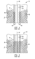
- FIG. 4 is a view of either the pressure side 46 or a suction side 48 of a blade 10 having discrete airfoil skin sections as disclosed in FIG 2 .
- the fore section outer airfoil skin 50 and aft section inner airfoil skin 58 typically include outer airfoil skin fibers 80 arranged in a prior art biax pattern, such as a criss cross pattern.
- the fore section outer airfoil skin 50 and aft section inner airfoil skin 58 may overlap the spar cap 18 to form outer skin/spar cap overlaps 82. These overlaps may be in the range of at least 2-3" long.
- FIG. 5 is a view of either the pressure side 46 or a suction side 48 of a blade 10 having a prior art continuous airfoil skin sections as disclosed in FIG 3 .
- the continuous outer airfoil skin 70 and the associated outer airfoil skin fibers 80 completely cover the spar cap 18, yet still form angles ⁇ and ⁇ with the spar cap fibers 38.
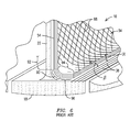
- FIG. 6 is a view of a web core 22 and spar cap 18, where the web skins 54 are discrete, as disclosed in FIG. 2 .
- a fillet 90 can be seen where the web core 22 meets the spar cap 18.
- the web skin 54 includes a first portion 92 that forms an angle with the spar cap 18, and a prior art transitioning portion 94 that transitions the web skin 54 from the first portion 92, across the fillet 90, to being parallel to the spar cap 18.
- the transitioning portion 94 overlaps the spar cap by a web/spar cap overlap 96. These overlaps may also be in the range of at least 2-3" long.
- Also visible within the web skin 54 are web fibers 98. It can be seen that within the web/spar cap overlap 96 the web fibers 98 again form angles ⁇ and ⁇ with the spar cap fibers 38.
- the continuous inner skins 74, 78 would overlap the fore section/spar cap joints 30 and the aft section/spar cap joints 32 in a manner similar to that shown in FIG. 5 where the continuous outer airfoil skin 70 completely cover the spar cap 18.
- the reinforcing fibers present within components of wind turbine blades provide reinforcement when in tension to resist blade deflection.
- the spar caps 18, which are separated by the web core 22 resist blade flex, particularly in directions 42 normal to the pressure side 46 and suction side 48. During this flex the web skins 54 provide structural reinforcement for the web core 22.
- the web fibers 98 transfer stress from one spar cap 18 to another during blade flex. However, in web/spar cap overlaps 96, where the spar cap fibers 38 and web fibers 98 are proximate each other they also form angles ⁇ and ⁇ with each other.
- angles ⁇ and ⁇ prevent smooth transition of the force from, for example, the spar cap fibers 38 directly to the web fibers 98.
- angles ⁇ and ⁇ When angles ⁇ and ⁇ are present the forces transfer from the spar cap fibers 38 and into the matrix material proximate the spar cap fibers 38.
- the matrix material begins to transfer the force to the web fibers 98 by yielding somewhat, but because the web fibers 98 are at an angle ( ⁇ and ⁇ ) to the spar cap fibers 38, and because the web fibers 98 can only offer resistance when in tension, (i.e. fibers only resist force along an axis of the fiber), the web fibers 98 initially only take a portion of the force present in the matrix material.
- the present inventor has devised a novel geometry for fibers in components made of fiber reinforced matrix composite materials that provides for improved transfer of force at joints of adjacent and structurally interdependent components.
- the novel geometry calls for the fibers within a first component and proximate a joint to approach being parallel to fibers in the adjacent component that are also proximate the joint.
- Approaching parallel means fiber ends in a harmonizing region approach an orientation that is more parallel to fibers in the adjacent component proximate the joint.
- Such a geometry reduces angles ( ⁇ and ⁇ ), and thereby increases a transfer of force to the adjacent fibers.
- FIG. 7 is a view of either the pressure side 46 or a suction side 48 of a blade 10 having discrete outer airfoil skin sections as disclosed in FIG 2 , but incorporating the novel fiber geometry disclosed herein.
- these teachings also apply to the inner skins where they meet the spar caps 18. For sake of clarity only one side is illustrated. It can be seen that in a non harmonizing region 100 the airfoil skin fibers 80 form a first pattern, for example a biax pattern.
- a skin may include one or more layers of fibers, and if each layer forms a biax pattern, then a skin may include one or more layers of biax fibers.
- a harmonizing region 102 which is separated from the non harmonizing region 100 by a harmonizing line 104, the airfoil skin fibers 80 change from their first pattern to an orientation where the ends of the airfoil skin fibers 80 within the harmonizing region curve toward being more parallel to the spar cap fibers 38.
- the harmonizing region 102 may span the relevant joint, but it need not. Shown is one geometry illustrating a gradual curving of the airfoil skin fibers 80, but other curve rates may be utilized. For example, the harmonizing region 102 may be smaller, which would necessitate a less gradual curve. Likewise, the harmonizing region 102 may be larger and thus a more gradual curve could be employed.
- An edge 106 of the harmonizing region 102 may be considered an asymptote for the curve of the ends of the airfoil skin fibers 80.
- a layer of fibers 80 may be formed by a single mat 101 that spans both regions 100, 102 as shown on the left side of FIG. 7 . In this instance, within the single mat the fibers 80 may have differing orientations.
- two or more separate mats may be used to complete a single layer. For example, a first mat 103 may be associated primarily with the non harmonizing region 100 and a second mat 105 may be associated primarily with the harmonizing region 102. As shown in the lower right of FIG.
- the first mat 103 and the second mat 105 may abut each other at a mat abutting line 107.
- the edges of the first mat 103 and the second mat 105 abut, and so individual fibers 80 abut.
- the mat abutting line 107 may be to the right or left of, or centered on the harmonizing line 104.
- the second mat When to the right of the harmonizing line 104, the second mat would have fibers 80 having patterns of both regions 100, 102, while the first mat would have fibers 80 having the pattern of the non harmonizing region 100.
- the first mat 103 would have fibers 80 of the non harmonizing region pattern
- the second mat 105 would have fibers 80 of the harmonizing pattern as disclosed above.
- the first mat 103 and the second mat 105 can be any size necessary.
- the second mat 105 may be anywhere from approximately five inches long to twelve inches long.
- the ends of the first mat 103 and the second mat 105 may overlap to form a mat overlap 108.
- This configuration may show improved force transfer from one mat to another due to the overlapping fibers 80.
- the mat overlap 108 may be to the right or left of, or cover the harmonizing line 104, as indicated by the arrows associate with the mat overlap 108.
- the first mat 103 would have fibers 80 having patterns of both regions 100, 102, while the second mat 105 would have fibers 80 having the pattern of the harmonizing region 102.
- the second mat 105 When to the right of the harmonizing line 104, the second mat 105 would have fibers 80 having patterns of both regions 100, 102, while the first mat 103 would have fibers 80 having the pattern of the non harmonizing region 100. In the exemplary embodiment where the harmonizing line 104 is within the mat overlap 108 each mat 103, 105 would have fibers of both regions 100, 102.
- the two non harmonizing regions 100 of FIG. 7 could be spanned by a single mat.
- the above described end configurations are possible for each end of the single mat.
- the fibers 80 could be configured to have as many curves and asymptotes as desired. Such an exemplary embodiment would simplify manufacturing by reducing from two to one the number of mats needed for one spar cap 18.
- the airfoil skin fibers 80 in the harmonizing region 102 of FIG. 7 each curve toward the edge 106 of the harmonizing region 102.
- individual airfoil skin fibers 80 may have differing paths within the harmonizing region 102. Varying patterns within the harmonizing region 102 may be used as necessary to provide optimized local force transfer characteristics.
- FIG. 8 shows a variation of the harmonizing region 102 of FIG. 7 , where various airfoil skin fibers 80 curve toward differing asymptotes. For clarity only one axis of the biax layer is shown, though in practice both axes would be present, such that the fibers with one axis help hold the fibers of the other axis in place.
- Airfoil skin fibers 80 of group 1 may use the edge 106 of the harmonizing region 102 as their asymptote 110.
- Airfoil skin fibers 80 of group 2 may approach a second asymptote 112.
- Airfoil skin fibers 80 of group 3 may approach a third asymptote 114, and airfoil skin fibers 80 of group 4 may approach a fourth asymptote 116.
- Four asymptotes have been used for illustration here, but any number of asymptotes is possible. It can be seen that the groups 1, 2, 3, 4, may be patterned in any way. As shown in FIG. 8 , there is a repeating pattern of 1, 2, 3, 4, 1, 2, 3, 4, etc. A variation could be 1, 1, 2, 2, 3, 3, 4, 4, 1, 1, 2, 2, 3, 3, 4, 4, etc, or any number of each group.
- ends (within the harmonizing region 102) of fibers of group 4 are shorter than are ends of fibers of group 1. Further, the ends of fibers of group 4 may not curve to the same degree or length as the ends of fibers of group 1. Consequently, the group 1 fibers may be more efficient at transferring load from the spar caps 18 to the skin. For this reason the pattern may be varied such that groups with shorter ends in the harmonizing region 102 are present with greater number within the pattern. An example of this is illustrated in FIG. 9 , where the pattern includes 4, 4, 4, 4, 3, 3, 3, 2, 2, 1, which may repeat. Thus, the ends of group 4, which may be less efficient than the ends of group 1, make up for any inefficiency by larger numbers. Any number of asymptotes, any number of groups, and any pattern of groupings may be envisioned to optimize force transfer.
- FIG. 10 is a view of either the pressure side 46 or a suction side 48 of a blade 10 having a continuous outer airfoil skin as disclosed in FIG 3 , but incorporating the novel fiber geometry disclosed herein. For sake of clarity only a portion of the airfoil skin fibers 80 are illustrated. In this exemplary embodiment, since the airfoil skin fibers 80 span the spar cap 18, there may not be an asymptote.
- the airfoil skin fibers 80 may curve as in FIGS 7-9 but instead of reaching an end point the airfoil skin fibers 80 may continue and blend with airfoil skin fibers 80 proximate the trailing edge 21 of the spar cap 18. This may form a harmonizing region 122.
- the harmonization region 122 may be wider than and encompass the spar cap 18, but it need not.
- a line of symmetry 120 may coincide with the longitudinal axis 40 of the spar caps 18. However, as with the patterns of FIGS 7-9 , the line of symmetry 120 may vary within the spar cap 18.
- the line of symmetry for a first group of fibers may be at a different location with respect to the longitudinal axis 40 than a line of symmetry for a second group of fibers.
- hybrid exemplary embodiments to combine layers of discrete outer airfoil skin sections with layers with a continuous outer airfoil skin in any manner consistent with the novel geometry disclosed herein.
- FIG. 11 is a variation of the configuration of FIG. 10 , where there exist several lines of symmetry 120 such that groups 201, 202, and 203 of airfoil skin fibers 80 may form symmetric patterns about respective lines of symmetry 120, and where the lines of symmetry 120 may be disposed at various locations. As with the teachings of FIGS. 8 and 9 , this will afford greater control over local force transfer characteristics.
- FIGS. 7-9 also apply to the inner skins where they meet the spar caps 18 or any joint where, at the joints, the components are essentially parallel and the skins is discrete.
- the teachings of FIGS 10-11 also apply to any components where components are essentially parallel, and one component can span the other component.
- FIG. 12 shows a web core 22 where it meets with a spar cap 18 at a web core/spar cap joint 34, where a discrete web skin 54 spans from the web core 22 to the spar cap 18 across the fillet 90.
- the web skin 54 includes a first portion 92 that forms an angle with the spar cap 18, and a transitioning portion 94 that transitions the web skin 54 from the first portion 92, across the fillet 90, to being parallel to the spar cap 18, to form an overlap 96.
- the novel geometry for the web fibers 98 includes a non harmonizing region 130 and a harmonizing region 132.
- the web fibers 98 form a first pattern, for example a biax pattern.
- a harmonizing region 132 which is separated from the non harmonizing region 130 by a harmonizing line 136, the web fibers 98 change from their first pattern to an orientation where the ends of the web fibers 98 within the harmonizing region curve toward being more parallel to the spar cap fibers 38.
- the harmonizing region 132 may span the relevant joint, but it need not.
- the harmonizing line 136 may extend into the first portion 92 by any desired amount. Shown is one geometry showing a gradual curving of the web fibers 98, but other curve rates may be utilized.
- the harmonizing region 132 may be smaller, which would necessitate a less gradual curve. Likewise, the harmonizing region 132 may be larger and thus a more gradual curve could be employed.
- An edge 138 of the harmonizing region 102 may be considered an asymptote for the curve of the ends of the web fibers 98.
- web fibers 98 within the overlap 96 may take any pattern such as, but not limited to those described in FIGS 7-9 . Similar to the exemplary embodiment shown in FIG. 7 , in order to effect the transition from the non harmonizing region 130 to a harmonizing region 132 a layer of fibers 80 may be formed by a single mat that spans both regions 130, 132.
- the fibers 80 may have differing orientations.
- two or more separate mats may be used to complete a single layer.
- a first mat 135 and a second mat 137 may abut each other at a mat abutting line.
- the ends of the first mat 135 and the second mat 137 may overlap to form a mat overlap 139.
- the above described web fiber geometry for the web core/spar cap joint 34 applies to embodiments with discrete inner skins and continuous inner skins since both cover the web core/spar cap joint 34.
- the novel geometry may also be applied to a leading edge 140 and/or trailing edge 142 of the blade 10 itself.
- the airfoil skin fibers 80 may form a leading edge harmonizing region 144 in which the ends of the airfoil skin fibers 80 approach being parallel to a respective portion of the leading edge 140 proximate the respective airfoil skin fiber ends.
- the airfoil skin fibers 80 may form a trailing edge harmonizing region 146 in which ends of the airfoil skin fibers 80 approach being parallel to a respective potion of the trailing edge 144 proximate the respective airfoil skin fiber ends.
- Such a configuration would improve strength near the edges of the blade where the blade halves are joined because all airfoil skin fibers 80 proximate a seam between the blade halves would be nearly parallel to each other.
- novel geometry for reinforcing fibers within reinforced composite materials being joined provides increased strength, and therefore blades may be designed using less material to accommodate a same load. Decreased material yields a decrease in manufacturing costs, and decreased weight yields more efficient operation. Consequently, the disclosure herein represents an improvement in the art.
Landscapes
- Engineering & Computer Science (AREA)
- Life Sciences & Earth Sciences (AREA)
- Sustainable Development (AREA)
- Sustainable Energy (AREA)
- Chemical & Material Sciences (AREA)
- Combustion & Propulsion (AREA)
- Mechanical Engineering (AREA)
- General Engineering & Computer Science (AREA)
- Wind Motors (AREA)
Applications Claiming Priority (1)
| Application Number | Priority Date | Filing Date | Title |
|---|---|---|---|
| US13/478,539 US20130315747A1 (en) | 2012-05-23 | 2012-05-23 | Wind turbine blade with improved geometry for reinforcing fibers |
Publications (2)
| Publication Number | Publication Date |
|---|---|
| EP2667018A2 true EP2667018A2 (fr) | 2013-11-27 |
| EP2667018A3 EP2667018A3 (fr) | 2017-07-19 |
Family
ID=48087385
Family Applications (1)
| Application Number | Title | Priority Date | Filing Date |
|---|---|---|---|
| EP13161636.9A Withdrawn EP2667018A3 (fr) | 2012-05-23 | 2013-03-28 | Pale d'éolienne à géométrie améliorée pour fibres de renforcement |
Country Status (4)
| Country | Link |
|---|---|
| US (1) | US20130315747A1 (fr) |
| EP (1) | EP2667018A3 (fr) |
| CN (1) | CN103423102A (fr) |
| CA (1) | CA2816257A1 (fr) |
Cited By (3)
| Publication number | Priority date | Publication date | Assignee | Title |
|---|---|---|---|---|
| WO2017103308A1 (fr) * | 2015-12-17 | 2017-06-22 | Emprending Business, S.L.L. | Revêtement intérieur pour des pales d'aérogénérateurs et procédé d'installation de celui-ci |
| ES2827151R1 (es) * | 2016-12-13 | 2021-05-21 | Emprending Business S L | Revestimiento interno para palas de aerogeneradores y procedimiento de montaje del mismo |
| GB2627440A (en) * | 2023-02-20 | 2024-08-28 | Dfm Blades Ltd | Method of manufacturing a spar structure, a spar structure for a wind blade, a wind blade, and an apparatus for manufacturing a spar structure |
Families Citing this family (9)
| Publication number | Priority date | Publication date | Assignee | Title |
|---|---|---|---|---|
| US9394881B2 (en) * | 2013-05-29 | 2016-07-19 | Siemens Aktiengesellschaft | Wind turbine blade and method of fabricating a wind turbine blade |
| ES2872401T3 (es) * | 2014-03-10 | 2021-11-02 | Siemens Gamesa Renewable Energy As | Un método para fabricar una pala de rotor para una turbina eólica |
| WO2016026862A1 (fr) * | 2014-08-18 | 2016-02-25 | Lm Wp Patent Holding A/S | Composant de pale de turbine d'éolienne renforcé |
| US20160177918A1 (en) * | 2014-12-18 | 2016-06-23 | General Electric Company | Wind turbine rotor blades with support flanges |
| PT3165762T (pt) * | 2015-11-06 | 2024-03-22 | Nordex Energy Spain S A | Pá de turbina eólica |
| NL2018263B1 (nl) * | 2017-01-31 | 2018-08-16 | Fibercore Ip Bv | Aerodynamisch of hydrodynamisch blad uit gelaagd materiaal |
| DK3899246T3 (da) * | 2018-12-19 | 2024-05-06 | Lm Wind Power As | Segmenteret rotorvinge med indvendig støttestruktur med varierende fiberorientering til stiftforstærkning |
| CN113107761A (zh) * | 2021-05-28 | 2021-07-13 | 张跃 | 一种风力发电叶片 |
| CN113958447B (zh) | 2021-11-10 | 2022-07-22 | 常州市宏发纵横新材料科技股份有限公司 | 一种模块化风电叶片弦向分块连接结构 |
Family Cites Families (31)
| Publication number | Priority date | Publication date | Assignee | Title |
|---|---|---|---|---|
| DE2334645C3 (de) * | 1973-07-07 | 1983-04-07 | M.A.N. Maschinenfabrik Augsburg-Nürnberg AG, 8000 München | Verfahren zur Herstellung eines Trägers aus Faserverbundprofil |
| DE2622163C3 (de) * | 1976-05-19 | 1983-05-26 | Messerschmitt-Bölkow-Blohm GmbH, 8000 München | Profilträger aus faserverstärktem Werkstoff |
| US4113910A (en) * | 1977-04-27 | 1978-09-12 | Rockwell International Corporation | Composite load coupler for reinforcing composite structural joints |
| US4256790A (en) * | 1978-01-19 | 1981-03-17 | Rockwell International Corporation | Reinforced composite structure and method of fabrication thereof |
| US4350728A (en) * | 1980-10-02 | 1982-09-21 | The United States Of America As Represented By The Secretary Of The Navy | Cross reinforcement in a graphite-epoxy laminate |
| US4560603A (en) * | 1983-10-27 | 1985-12-24 | Ltv Aerospace And Defense Company | Composite matrix with oriented whiskers |
| US4734146A (en) * | 1986-03-31 | 1988-03-29 | Rockwell International Corporation | Method of producing a composite sine wave beam |
| US4808461A (en) * | 1987-12-14 | 1989-02-28 | Foster-Miller, Inc. | Composite structure reinforcement |
| JPH0823095B2 (ja) * | 1989-06-06 | 1996-03-06 | 東レ株式会社 | 補強繊維織物 |
| FR2658841B1 (fr) * | 1990-02-26 | 1993-06-11 | Aerospatiale | Procede et dispositif pour la realisation d'elements d'armature composes de fibres resistantes. |
| FR2687174B1 (fr) * | 1992-02-11 | 1995-09-22 | Aerospatiale | Procede pour la realisation d'une armature de fibres pour piece de matiere composite a parois non coplanaires, et piece composite comportant une telle armature. |
| US5466506A (en) * | 1992-10-27 | 1995-11-14 | Foster-Miller, Inc. | Translaminar reinforcement system for Z-direction reinforcement of a fiber matrix structure |
| US5445860A (en) * | 1992-12-29 | 1995-08-29 | Gff Holding Company | Tufted product having an improved backing |
| US5375324A (en) * | 1993-07-12 | 1994-12-27 | Flowind Corporation | Vertical axis wind turbine with pultruded blades |
| ES2208694T3 (es) * | 1995-08-21 | 2004-06-16 | Foster-Miller, Inc. | Sistema para insertar elementos en estructura de material compuesto. |
| US5836715A (en) * | 1995-11-19 | 1998-11-17 | Clark-Schwebel, Inc. | Structural reinforcement member and method of utilizing the same to reinforce a product |
| US5789061A (en) * | 1996-02-13 | 1998-08-04 | Foster-Miller, Inc. | Stiffener reinforced assembly and method of manufacturing same |
| US5639535A (en) * | 1996-06-06 | 1997-06-17 | The Boeing Company | Composite interleaving for composite interfaces |
| US7056576B2 (en) * | 2001-04-06 | 2006-06-06 | Ebert Composites, Inc. | 3D fiber elements with high moment of inertia characteristics in composite sandwich laminates |
| US7731046B2 (en) * | 2001-04-06 | 2010-06-08 | Ebert Composites Corporation | Composite sandwich panel and method of making same |
| GB0424481D0 (en) * | 2004-11-05 | 2004-12-08 | Rolls Royce Plc | Composite aerofoil |
| US7371043B2 (en) * | 2006-01-12 | 2008-05-13 | Siemens Power Generation, Inc. | CMC turbine shroud ring segment and fabrication method |
| EP1880833A1 (fr) * | 2006-07-19 | 2008-01-23 | National University of Ireland, Galway | Articles composites comprenant des matériaux thermoplastiques polymerisables in-situ et méthodes de fabrication associées |
| WO2008052677A2 (fr) * | 2006-11-02 | 2008-05-08 | Lignum Vitae Limited | Aube de rotor d'éolienne et éolienne dotée d'une telle aube |
| US7600979B2 (en) * | 2006-11-28 | 2009-10-13 | General Electric Company | CMC articles having small complex features |
| US7887730B2 (en) * | 2007-08-28 | 2011-02-15 | Abe Karem | Self-tooling composite structure |
| US8167569B2 (en) * | 2007-12-21 | 2012-05-01 | General Electric Company | Structure and method for self-aligning rotor blade joints |
| US20090196756A1 (en) * | 2008-02-05 | 2009-08-06 | General Electric Company | Wind turbine blades and method for forming same |
| US7963747B2 (en) * | 2009-04-02 | 2011-06-21 | General Electric Company | Braided wind turbine blades and method of making same |
| US20110052404A1 (en) * | 2009-08-25 | 2011-03-03 | Zuteck Michael D | Swept blades with enhanced twist response |
| AU2010294625A1 (en) * | 2009-12-22 | 2011-07-07 | Mitsubishi Heavy Industries, Ltd. | Wind turbine blade and wind turbine generator using the same |
-
2012
- 2012-05-23 US US13/478,539 patent/US20130315747A1/en not_active Abandoned
-
2013
- 2013-03-28 EP EP13161636.9A patent/EP2667018A3/fr not_active Withdrawn
- 2013-05-21 CA CA2816257A patent/CA2816257A1/fr not_active Abandoned
- 2013-05-23 CN CN2013101945371A patent/CN103423102A/zh active Pending
Non-Patent Citations (1)
| Title |
|---|
| None |
Cited By (5)
| Publication number | Priority date | Publication date | Assignee | Title |
|---|---|---|---|---|
| WO2017103308A1 (fr) * | 2015-12-17 | 2017-06-22 | Emprending Business, S.L.L. | Revêtement intérieur pour des pales d'aérogénérateurs et procédé d'installation de celui-ci |
| CN108474344A (zh) * | 2015-12-17 | 2018-08-31 | 安普兰庭商业公司 | 用于风力涡轮机叶片的内覆层及用于安装该内覆层的方法 |
| US11015571B2 (en) | 2015-12-17 | 2021-05-25 | Emprending Business, S.L. | Inner covering for wind turbine blades and method for mounting same |
| ES2827151R1 (es) * | 2016-12-13 | 2021-05-21 | Emprending Business S L | Revestimiento interno para palas de aerogeneradores y procedimiento de montaje del mismo |
| GB2627440A (en) * | 2023-02-20 | 2024-08-28 | Dfm Blades Ltd | Method of manufacturing a spar structure, a spar structure for a wind blade, a wind blade, and an apparatus for manufacturing a spar structure |
Also Published As
| Publication number | Publication date |
|---|---|
| CN103423102A (zh) | 2013-12-04 |
| CA2816257A1 (fr) | 2013-11-23 |
| EP2667018A3 (fr) | 2017-07-19 |
| US20130315747A1 (en) | 2013-11-28 |
Similar Documents
| Publication | Publication Date | Title |
|---|---|---|
| EP2667018A2 (fr) | Pale d'éolienne à géométrie améliorée pour fibres de renforcement | |
| US9951750B2 (en) | Rotor blade with interior shelf for a flat plate spar cap | |
| US20150023799A1 (en) | Structural Member with Pultrusions | |
| DK2971756T3 (en) | WINDMILL LEVELS WITH LAYER-SHARED MULTI-COMPONENT BULLETS AND ASSOCIATED SYSTEMS | |
| US8075278B2 (en) | Shell structure of wind turbine blade having regions of low shear modulus | |
| EP3517732B1 (fr) | Aube composite renforcé et procédé de fabrication d'une aube | |
| US20110135486A1 (en) | Belt of a rotor blade of a wind power plant | |
| EP2910365B1 (fr) | Élément structural composite et caisson de torsion | |
| CN108472902B (zh) | 关于风轮机叶片制造的改进 | |
| US20110052404A1 (en) | Swept blades with enhanced twist response | |
| EP2552678A1 (fr) | Elément structurel composite | |
| EP3712424A1 (fr) | Pale de turbine éolienne et éolienne | |
| EP3106656B1 (fr) | Modules de pale de turbine éolienne et des pales de turbine éolienne | |
| US10072632B2 (en) | Spar cap for a wind turbine rotor blade formed from pre-cured laminate plates of varying thicknesses | |
| US20190128334A1 (en) | Composite flexible coupling | |
| US20110052407A1 (en) | Swept blades utilizing asymmetric double biased fabrics | |
| CA2320606C (fr) | Bordures protectrices pour courbures composites | |
| EP3230052A1 (fr) | Procédé de fabrication de coussinets pour structures composites et structures composites comprenant les coussinets | |
| EP3034863B1 (fr) | Pale d'éolienne et éolienne comprenant une telle pale | |
| US20140027573A1 (en) | Aircraft fuselage structural element with variable cross-section | |
| DK3034865T3 (en) | ARRANGEMENT OF PULTRUDED SPELLS | |
| KR20170129634A (ko) | 모노리식 블레이드, 모노리식 블레이드를 구비한 회전익기 로터, 및 관련된 회전익기 | |
| EP4176173B1 (fr) | Pale d'éolienne | |
| US10040546B2 (en) | Bar of composite matrix material | |
| EP4132776B1 (fr) | Stratifié principal, pale d'éolienne comprenant un tel stratifié principal et procédés de fabrications. |
Legal Events
| Date | Code | Title | Description |
|---|---|---|---|
| PUAI | Public reference made under article 153(3) epc to a published international application that has entered the european phase |
Free format text: ORIGINAL CODE: 0009012 |
|
| AK | Designated contracting states |
Kind code of ref document: A2 Designated state(s): AL AT BE BG CH CY CZ DE DK EE ES FI FR GB GR HR HU IE IS IT LI LT LU LV MC MK MT NL NO PL PT RO RS SE SI SK SM TR |
|
| AX | Request for extension of the european patent |
Extension state: BA ME |
|
| 17P | Request for examination filed |
Effective date: 20140417 |
|
| RBV | Designated contracting states (corrected) |
Designated state(s): AL AT BE BG CH CY CZ DE DK EE ES FI FR GB GR HR HU IE IS IT LI LT LU LV MC MK MT NL NO PL PT RO RS SE SI SK SM TR |
|
| PUAL | Search report despatched |
Free format text: ORIGINAL CODE: 0009013 |
|
| AK | Designated contracting states |
Kind code of ref document: A3 Designated state(s): AL AT BE BG CH CY CZ DE DK EE ES FI FR GB GR HR HU IE IS IT LI LT LU LV MC MK MT NL NO PL PT RO RS SE SI SK SM TR |
|
| AX | Request for extension of the european patent |
Extension state: BA ME |
|
| RIC1 | Information provided on ipc code assigned before grant |
Ipc: F03D 1/06 20060101AFI20170612BHEP |
|
| RAP1 | Party data changed (applicant data changed or rights of an application transferred) |
Owner name: SIEMENS AKTIENGESELLSCHAFT |
|
| STAA | Information on the status of an ep patent application or granted ep patent |
Free format text: STATUS: THE APPLICATION IS DEEMED TO BE WITHDRAWN |
|
| 18D | Application deemed to be withdrawn |
Effective date: 20180120 |