EP2672029B1 - Dispositif d'actionnement pour la soupape d'un réservoir de chasse - Google Patents
Dispositif d'actionnement pour la soupape d'un réservoir de chasse Download PDFInfo
- Publication number
- EP2672029B1 EP2672029B1 EP12171285.5A EP12171285A EP2672029B1 EP 2672029 B1 EP2672029 B1 EP 2672029B1 EP 12171285 A EP12171285 A EP 12171285A EP 2672029 B1 EP2672029 B1 EP 2672029B1
- Authority
- EP
- European Patent Office
- Prior art keywords
- actuator
- mounting frame
- bearing
- actuator button
- button
- Prior art date
- Legal status (The legal status is an assumption and is not a legal conclusion. Google has not performed a legal analysis and makes no representation as to the accuracy of the status listed.)
- Active
Links
Images




Classifications
-
- E—FIXED CONSTRUCTIONS
- E03—WATER SUPPLY; SEWERAGE
- E03D—WATER-CLOSETS OR URINALS WITH FLUSHING DEVICES; FLUSHING VALVES THEREFOR
- E03D5/00—Special constructions of flushing devices, e.g. closed flushing system
- E03D5/02—Special constructions of flushing devices, e.g. closed flushing system operated mechanically or hydraulically (or pneumatically) also details such as push buttons, levers and pull-card therefor
- E03D5/028—Pusher plates and actuating mechanisms for built-in cisterns
Definitions
- the present invention relates to an operating device for a drain valve of a cistern according to the preamble of claim 1.
- Actuators for drainage valves of cisterns are known in the art.
- the actuator after EP 1 491 690 shows a frame to be mounted in an opening in a wall, wherein a cover plate is in communication with the frame and extends completely over the frame and the opening. In the cover plate then actuated by the user keys are stored. The keys act on actuation of an actuator element, for example on a pusher rod, with which then the flushing in the cistern is triggered.
- the assembly effort or the manufacturing cost of such a cover plate is relatively high. Furthermore, a relatively accurate positioning between the cover plate and the frame is required, so that the keys act on the actuator element. In addition, the keys can get caught with the cover plate, resulting in malfunction.
- the DE 20 2006 013 850 shows an actuator according to the preamble of claim 1 and is considered as the closest prior art. Also the DE 20 2006 013 003 , the DE20 2006 012 664 and the EP 2 388 380 show actuators for the sanitary appliances. Also from these actuators the disadvantage that they are not easy to install.
- the invention has for its object to provide an actuating device mentioned above, which is easier to manufacture or assemble.
- the actuator should be safer to operate when flushing.
- the actuating device for a drain valve of a cistern comprises or includes a mounting frame, an actuating button and at least one actuator element for actuating the drain valve in the cistern, which actuator element can be actuated with the actuating button.
- the mounting frame is inserted in operation in a wall opening in a wall.
- the actuator element is preferably arranged between the mounting frame and the actuating button.
- the actuating button is movable with respect to the mounting frame in the Spülauslect from a starting position to an end position, in particular pivotable, formed
- the actuating button is directly and directly mounted on the mounting frame. In other words, it can also be said. that the actuating button is directly, ie directly, in communication with the mounting frame.
- the mounting frame defines a plane, wherein the actuating button is pivotable about at least one axis which is parallel to the plane to this plane.
- the actuating button is pivotable about exactly one axis, which is located centrally to the actuating button, which can be spoken here of a rocking motion.
- the actuating button is pivotable about exactly two spaced apart axes. In this way, in both embodiments, two actuator elements can be actuated, so that a dual-flush can be triggered.
- the mounting frame and the actuating button are connected to each other via at least one bearing point, wherein in each case two spaced bearing points are arranged per axis in particular.
- Said bearing point comprises a receiving element and a bearing element, wherein the bearing element is designed to be hooked into the receiving element.
- the bearing element is sprung trained in a design with a spring and in another embodiment, the bearing element is rigid.
- One bearing element is sprung per axle and the other bearing element is rigidly formed.
- the bearing element is preferably a bearing pin, wherein the bearing pin can be suspended in the corresponding receptacle or in the mounting frame.
- the bearing points on the actuating button on the shape of recordings and the bearing points on the mounting frame have the shape of bearing pin, wherein the bearing pins protrude into the receptacles.
- the actuating button and / or the mounting frame have at least one guide element, wherein the guide element guides the movement between the actuating button and mounting frame.
- the guide element projects, for example, into a guide opening on the actuating button or on the mounting frame.
- the guide element has a stop element, which engages the mounting frame, so that a movement of the actuating button from the starting position against the direction of the end position, can be blocked, said with the stop member, which is present on the mounting frame, said axis is providable. consequently then the actuating button is pivoted about the stop element.
- the actuating device comprises exactly one single actuating button.
- the actuating button is designed as a flat plate.
- the flat plate is preferably formed in one piece.
- the actuating button is seen in a direction perpendicular to the actuating button larger than the mounting frame, so that the mounting frame seen in said direction is substantially completely covered by the operation button.
- the operation button then covers the wall opening. The user, in use, is essentially only the operating button of the operating device, which has an extremely high aesthetic value.
- At least one return element is arranged between the mounting frame of the actuating button, wherein the restoring element provides a restoring force on the actuating button, so that the actuating button is moved into the bearing or the recording. More preferably, a plurality of return elements are arranged so that the actuating button comes to lie parallel to the mounting frame.
- the actuating device further comprises at least one actuating lever, which is actuated by the actuating button and acts on the actuator element.
- the return element acts on the actuating lever on the actuating lever.
- an actuator 1 for a drain valve of a cistern is shown in plan view.
- the actuator 1 essentially comprises one in the FIG. 1 invisible mounting frame 2, an actuating button 3, and at least one actuator element 4, which here in the FIG. 1 is not visible.
- the actuator 4 is operable with the actuating button 3 and acts on the Spülauslect in a cistern of a toilet or urinal. The flushing can thus be triggered via the actuator element 4.
- the actuating key 3 essentially comprises two areas, namely a left area 5 and a right area 6. These two areas 5, 6 are separated by a visualized dividing line 7. A pressure by the user on the left area 5, which is shown here larger, triggers a full flush, while a pressure on the right area 6 triggers a corresponding partial flush.
- two actuator elements are arranged. The left and right areas can also be reversed accordingly.
- the actuating button 3 is preferably formed as a flat plate with a front surface 11 and a rear surface 22. Particularly preferably, the actuating button 3 is formed essentially in one piece.
- the actuating device 1 comprises exactly one single actuating button 3.
- a particularly simple design of the actuating device can be provided with the possibility of triggering a dual-flushing.
- FIG. 2 which shows the actuator 1 in a side view
- the actuator 1 can be well recognized that it is directly and directly to the mounting frame 2 in connection with the operating button 3 or directly and directly mounted on the mounting frame 2.
- a direct and direct connection or storage is meant that the actuating button 3 without further elements, such as a frame or a cover plate, is connected directly to the mounting frame 2. Consequently, it can also be said that the operation button 3 is frameless or without cover plate. In this way it can be prevented that the actuating button 3 hooked to a mounting frame, as these are known from the prior art.
- a complex positioning between the actuating button 3 and the actuator element 4 is eliminated because the actuating button 3 can act on the actuator element 4 with the entire rear surface 22. In addition, eliminates the production and installation of a corresponding cover plate.
- the actuating button 3 is relative to the mounting frame 2 in the Spülausates from an initial position to an end position movable, in particular pivotable formed. Consequently, therefore, the actuating button 3 can be moved from the starting position during the operation to the mounting frame 2 toward the end position. After flushing then the operation button 3 is away from the mounting frame 2, that is moved from the end position to the starting position.
- the mounting frame 2 is typically embedded in an opening in a masonry and communicates with elements of the cistern.
- the wall opening 8 is in the FIG. 2 symbolically indicated.
- the wall opening 8 extends from a Wall 9 in said wall 9 into it.
- the wall 9 is set back relative to the actuating button 3, so that the actuating button 3 with respect to the wall 9 is movable. In other words, it can also be said that the actuating button is moved in the Spülauslect from the starting position in the direction of wall 9 in the end position.
- the movement is represented by the arrow B.
- the actuating button 3 seen in a direction perpendicular to the actuating button 3 is greater than the mounting frame and also larger than the wall opening 8 in the wall 9 is formed.
- the mounting frame 2 and the wall opening in a direction perpendicular to the surface 11 of the actuating button 3 is substantially completely covered by the actuating button 3, which in the FIG. 1 is clearly recognizable.
- the full coverage has the advantage that the user does not see the mounting frame 2 or parts of the wall opening 9 with built-in actuator 1, but only the surface of the actuating button 3 perceives, as in the FIG. 1 is shown accordingly.
- the training as a flat actuating button 3 is visually very appealing because the user perceives in use only a single element. Also, such an operation button 3 is easier to clean.
- the actuating button 3 has a greater extent than the mounting frame.
- the mounting frame 2 or the wall 9 define a plane 10.
- the plane 10 extends substantially parallel to the wall 9 and can be defined by corresponding elements of the mounting frame 2.
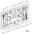
- a circumferential flange 26 of the mounting frame as this in the Figures 2 and 4 can be recognized, the said level 10 ready.
- the mounting frame 2 comprises according to the FIG. 4 essentially an interior 27, which is bounded by a rear wall 28 and peripheral side walls 29.
- the side walls 29 then joins a circumferential flange 26 at.
- the rear wall 28 furthermore comprises at least one opening 30 through which elements can be guided in the direction of the cistern.
- the actuating button 3 is preferably pivotable about at least one axis A1, A2, A3. There are essentially two different embodiments conceivable. In a first embodiment, the actuating button 3 is pivoted about exactly one axis A1. The axis A1 preferably runs centrally through the actuating button 3. In a second embodiment, the actuating button 3 is pivoted about two spaced apart axes A2, A3.
- the actuating button 3 pivots on the plane 10 at a pressure on the left area 5 and the right area 6 about the axis A1. This is a kind of rocking movement in two different directions of pivoting about the axis A1.
- the actuating button 3 pivots at a pressure on the right area 6 about the axis A2 on the plane 10 back.
- the actuating button 3 pivots about the axis A3 with respect to the plane 10th
- the operation button 3 comes to rest with the surface 11 at an angle to the plane 10.
- the actuating button 3 is pivoted about the respective axis A1 or A2 or A3 at an angle to the sheet plane.
- the leaf level according to the FIG. 1 corresponds essentially to the plane 10, which is defined by the installation arms 2 and the wall 9.
- the axes A1, A2, A3 can run both in the horizontal or in the vertical. It is also conceivable that the axes A1, A2, A3 extend at an angle or inclined to the horizontal or to the vertical.
- the dividing line 7 is then correspondingly printed in a different position in order to signal the user the direction of actuation.
- the dividing line 7 preferably runs parallel to the axes A1, A2, A3.
- the actuating button 3 is shown in a rear perspective view with the rear surface 22 clearly visible.
- the in the FIG. 3 shown actuating button 3 is suitable for use as a first embodiment with an axis A1.
- the operation key 3 for use as a second embodiment with two axes A2, A3 is in the FIGS. 6a to 6c shown and then explained further below.
- the bearing 12 preferably comprises a bearing element 14, 31 and a receiving element 13.
- the bearing element 14, 31 is formed in the receiving element 13 hooked. In the suspended state, the bearing element 14, 31 engages or protrudes into the receiving element 13, whereby the connection between the bearing element 14, 31 and receiving element 13 is provided.
- bearing element 14, 31 and receiving element 13 are at least partially matching or complementary to each other.
- the bearing element 14 may be formed sprung with a spring 17, as here the upper bearing element 14 in the FIG. 3 , or the bearing member 14 may be formed as a rigid bearing member 31, as the lower bearing member 31st
- the bearing element 14, 31 is preferably a pin 14, 31, which can be spoken by a spring-loaded bearing pin 14 in the case of the presence of the spring 17 and a rigid bearing pin 31.
- the operation button 3 can be easily hooked into the receptacles 13.
- the bearing pin 14 is pressed in a first step with the spring 17 in the corresponding receptacle 13 and the spring springs accordingly.
- the actuating button 3 can be pivoted in the direction of mounting frame 2 and also with respect to the corresponding receptacle 13 are positioned. If the installer then releases the actuating button 3, then the spring 17 and the rigid spring relax Journal 31 automatically engages in the corresponding receptacle 13 and is stored in these recordings. Thus, the installer can very easily hang the operating button 3 on the mounting frame 2.
- the bearing 12 on the mounting frame 2 in the shape of receptacles 13 and the bearing 12 on the actuating button 3 have the shape of bearing pins 14, 31.
- the bearing pins 14 protrude into the receptacles 13 and are stored there by the receptacles 13 accordingly.
- the bearing 12 on the actuating button 3 but also have the shape of receptacles 13 and then the bearing 12 is formed on the mounting frame 2 as a bearing pin 14, 31.
- the bearing pin 14 extends along an axis M. Likewise, portions of the receptacles 13 also extend along a corresponding axis M.
- the axes M extend parallel to said plane 10.
- the actuating button 3 is pivotable about this axis M.
- the axis M is substantially the axis A1 or A2, as already explained above.
- the bearing pins 14 are formed directly on the actuating button 3.
- the actuating button 3 can be injected, for example, from a plastic.
- the journals 14 may be parts of a frame 23.
- the frame 23 is connected via the rear surface 22 of the actuating button 3 with the actuating button 3 in connection.
- the actuating button 3 comprises essentially two parts, namely the actuating button 3 itself and the frame 23 which is materially connected to the actuating button 3.
- the frame 23 is preferably glued to the rear surface 22, whereby a material-locking connection between frame 23 and actuating button 3 can be provided.
- a bearing 12 preferably consists of a pair comprising a bearing pin 14, 31 and receptacle 13.
- the pairings are spaced apart from each other. In each case two pairs are arranged on a common center axis M, wherein the two bearing pins 14 and the two receptacles 13 run collinear.
- FIG. 4 can be seen that the receptacle 13 with respect to the direction of movement of the actuating button 3 from the starting position into the flushing position as a channel 15, here as an open channel 15, is formed.
- the channel 15 is thus formed in a direction perpendicular to the plane 10 seen from the actuating button 3 in the direction of mounting frame 2 open. Consequently, the bearing pin 14 can be moved in the direction of movement with respect to the fixed receptacle 13.
- the bearing pin 14 can be moved through this open channel 15.
- the channel 15 is designed to be closed to the actuating button 3, for which purpose the channel 15 has a wall 16.
- the wall 16 provides a stop for the bearing pin 14. The stop thus ensures that the actuating button 3 can not be moved from the starting position against the usual movement in the flushing position.
- the wall 16 essentially has a stop section 24, from which two wall sections 25 extend. The two wall sections 25 then preferably run parallel or at an angle or inclined to one another. In the latter case, the cross section of the open channel 15 increases in the direction from the starting position in the scavenging position.
- the angled design has the advantage that in this way the pivoting of the actuating button 3 is made possible.
- FIGS. 5a to 5c the situation in the operation of the operation button 3 according to the first embodiment will be explained.
- the operation button 3 in the starting position and in the FIG. 5c shown in the end position.
- the actuating button 3 pivots about the axis A1, which extends perpendicular to the drawing surface here.
- the operation button 3 pivots to the other side.
- the bearing elements 14, 31 preferably remain in the corresponding receptacle 13. Under great effort but it can still come to a movement in the direction of the channel 15 of the receptacle 13, which has the advantage that so undesirable forces can be compensated.
- the movement can be guided by means of guide elements 33 which protrude into guide openings 34.
- the guide elements 33 are pins 33 projecting from the actuating button 3, which project into the guide openings 34 in the mounting frame 2.
- Guide elements 33 and guide openings 34 are also in the Figures 3 and 4 recognizable.
- the guide elements 33 each have a stop element 32 at their ends. This stop element 32 acts on the back 35 of the mounting frame 2, so that a stop against movement from the starting position to the front, ie against the direction of normal operation towards the end position, is provided.
- the stop member 32 at the same time the pivot axis A2 ready, about which the actuating button 3 pivots to the mounting frame 2.
- the bearing element 14 is moved out of the recess 13 in the direction of the channel 15. With a pressure on the left region 5 or the right region 6, therefore, the bearing element 14 is moved out of the recess.
- the stop elements 32 arranged on the left are in contact with the rear side 35 of the mounting frame 2
- the stop elements 32 arranged on the right are in contact with the rear side 35 of the mounting frame 2 ,
- stop element 32 and the back 35 serve as a pivot bearing or pivot about which the actuating button is pivoted.
- the actuating button 3 can be pivoted so far until the actuating button 3 is present with the surface 11 on the wall 9 or the mounting frame 2. With the actuating button 3, the actuator element 4 is then actuated and the flushing is triggered.
- the actuator 1 additionally has an optional operating lever 19.
- This actuating lever 19 acts here on the actuator element 4 with a projection 20.
- the actuating button 3 acts on the actuating lever 19, which is then correspondingly pivoted and strikes the actuator element 4.
- the return element preferably acts on this actuating lever 19 on the actuating button 3.
- the actuating lever 19 is pivotally mounted in two mounting points 21 in the mounting frame 3. If now the optional actuating lever 19 is arranged between the actuator element 4 and the actuating button 3, then the surface 11 of the actuating button 3 acts on the actuating lever 19, which is then pivoted about the corresponding bearing point 21.
- the actuating lever 19 then acts with its projection 20 on the actuator element 4, whereby the flushing is triggered.
- a return element 18 is arranged here in the shape of a plurality of leaf springs 18 between the mounting frame 2 and the actuating button 3.
- the return elements 18 act on the rear surface 22 of the actuating button 3 and are connected via the rear wall 28 with the mounting frame 2 in connection.
- the return element 18 provides a restoring force to the actuating button 3 ready.
- the operation key 3 is moved out of the scavenging position to the home position.
- the actuating button 3 then rests in accordance with the bearing point 12th
- the actuator element 4 preferably has the shape of a pneumatic pressure transducer in the present embodiment.
- a pressure pulse is generated by the pneumatic pressure transducer, which acts on a Spülventilan Aunt.
- a pressure hose can then be passed through the openings 30 in the cistern.
- the actuator element 4 it should also be noted that the actuator element 4 is arranged between the actuating button 3 and the mounting frame 2.
- the actuator element 4 is particularly preferably connected to the mounting frame 2 or is mounted in the mounting frame 2.
- the actuator 1 has the advantage that a very simple manufacture and assembly of the actuator 1 is allowed. In addition, aesthetic requirements can also be taken into account. Further, the actuator 1 is safer in use because it can not come to a snag between the operation keys and a frame.
Landscapes
- Engineering & Computer Science (AREA)
- Mechanical Engineering (AREA)
- Aviation & Aerospace Engineering (AREA)
- Health & Medical Sciences (AREA)
- Life Sciences & Earth Sciences (AREA)
- Hydrology & Water Resources (AREA)
- Public Health (AREA)
- Water Supply & Treatment (AREA)
- Lock And Its Accessories (AREA)
- Sanitary Device For Flush Toilet (AREA)
Claims (13)
- Un dispositif d'actionnement pour la soupape d'un réservoir de chasse comprenant ou incluant un châssis de montage (2), un bouton d'actionnement (3) et au moins un élément d'actionnement (4) pour l'actionnement de la soupape du réservoir de chasse, lequel élément d'actionnement (4) peut être actionné avec le bouton d'actionnement (3),
où lors du rinçage, le bouton d'actionnement (3) peut être pivoté d'une position initiale dans une position finale par rapport au châssis de montage (2), où le bouton d'actionnement (3) est monté directement et immédiatement sur le châssis de montage (2),
où le châssis de montage (2) définit un plan (10), dans lequel le bouton d'actionnement (3) peut être pivoté autour d'au moins un axe (A1, A2, A3), qui est parallèle au plan (10),
où le châssis de montage (2) et le bouton d'actionnement (3) sont reliés les uns aux autres au moyen de positions d'appui (12), où à chaque axe (A1, A2, A3), deux positions d'appui (12) sont disposées, qui sont espacées l'une de l'autre, lesquelles positions d'appui (12) comprennent chacune un élément de réception (13) et un élément d'appui (14, 31), caractérisé
en ce que chaque élément d'appui (14) est formé de manière à être accroché dans un élément de réception (13), où un élément d'appui (14) de la une position d'appui (12) est prévu de manière suspendu avec un ressort (17) et où l'élément d'appui (31) de l'autre position d'appui (12) est prévu de manière rigide. - Le dispositif selon la revendication 1, caractérisé en ce que chaque élément d'appui (14, 31) est un tourillon (14, 31), où le tourillon (14, 31) peut être accroché à la réception correspondante (13) ou dans le châssis de montage (2), respectivement.
- Le dispositif selon la revendication 2, caractérisé en ce que les tourillons (14, 31) sont assignés au bouton d'actionnement (3) et les réceptions (13) sont assignées au châssis de montage (2).
- Le dispositif selon la revendication 2, caractérisé en ce que les tourillons (14, 31) sont assignés au châssis de montage (2) et les réceptions (13) sont assignées au bouton d'actionnement (3).
- Le dispositif selon l'une quelconque des revendications 2 à 4, caractérisé en ce que le tourillon (14) s'étend le long d'un axe (M) et en ce que la réception (13) s'étend le long dudit axe (M), où l'axe (M) est parallèle audit plan (10) et où le bouton d'actionnement (3) peut être pivoté autour dudit axe (M).
- Le dispositif selon l'une quelconque des revendications précédentes, caractérisé en ce que deux positions d'appui (12) sont présents, qui définissent un seul axe (A1), ou en ce que quatre positions d'appui (12) sont présents, qui définissent deux axes (A1, A2).
- Le dispositif selon l'une quelconque des revendications 2 à 6, caractérisé en ce que l'élément de réception (13) est réalisé sous la forme d'un canal (15) à partir de la position initiale à la position finale par rapport à la direction de déplacement du bouton d'actionnement (3), où, lors de l'actionnement, le tourillon (14, 31) est mobile à travers ledit canal ouvert (15), et où le canal (15) est de préférence fermée par une paroi (16) en direction du bouton d'actionnement (3) et fournit donc une butée pour le tourillon (14).
- Le dispositif selon l'une quelconque des revendications précédentes, caractérisé en ce que le bouton d'actionnement (3) et/ou le châssis de montage (2) sont pourvus d'au moins un élément de guidage (33), où l'élément de guidage (33) guide le mouvement entre le bouton d'actionnement (3) et le châssis de montage (2).
- Le dispositif selon la revendication 8, caractérisé en ce que l'élément de guidage (33) est pourvu d'un élément de butée (32), qui intervient avec le châssis de montage (2), de sorte qu'un mouvement du bouton d'actionnement (3) est bloquée depuis la position initiale dans une direction opposée à la position finale, où un desdits axes (A1, A2, A3) est définie par l'élément de butée.
- Le dispositif selon l'une quelconque des revendications précédentes, caractérisé en ce que le bouton d'actionnement (3) peut être pivoté autour d'un premier axe (A1) qui est parallèle au plan (10), et en outre, le bouton d'actionnement (3) peut être pivoté autour d'un deuxième axe (A2), qui est parallèle au plan et au première axe (A1).
- Le dispositif selon l'une quelconque des revendications précédentes, caractérisé en ce que le dispositif d'actionnement (1) comprend exactement un seul bouton d'actionnement (3) et/ou en ce que le bouton d'actionnement (3) est réalisé sous la forme d'une plaque plane et/ou le bouton d'actionnement (3) est plus grande que le châssis de montage (2) dans une direction perpendiculaire vu sur le bouton d'actionnement (3), de sorte que le châssis de montage (2) est complètement recouvert par le bouton d'actionnement (3), vu dans ladite direction.
- Le dispositif selon l'une quelconque des revendications précédentes, caractérisé en ce qu'au moins un élément de rappel (18) est disposé entre le châssis de montage (2) et le bouton d'actionnement (3), où l'élément de rappel (18) fournit une force de rappel sur le bouton d'actionnement (3), de sorte que le bouton d'actionnement (3) est déplacé vers la position de repos (12) ou est déplacé de la position finale à la position initiale, respectivement.
- Le dispositif selon l'une quelconque des revendications précédentes, caractérisé en ce que le dispositif d'actionnement (1) comprend en outre au moins un levier d'actionnement (19), qui peut être actionné par le bouton d'actionnement (3) et qui agit sur l'élément d'actionnement (4) et/ou en ce que l'élément de rappel (18) agit sur le bouton d'actionnement (3) par l'intermédiaire du levier d'actionnement (19).
Priority Applications (2)
| Application Number | Priority Date | Filing Date | Title |
|---|---|---|---|
| DK12171285.5T DK2672029T3 (da) | 2012-06-08 | 2012-06-08 | Aktiveringsindretning til en afløbsventil i en wc-cisterne |
| EP12171285.5A EP2672029B1 (fr) | 2012-06-08 | 2012-06-08 | Dispositif d'actionnement pour la soupape d'un réservoir de chasse |
Applications Claiming Priority (1)
| Application Number | Priority Date | Filing Date | Title |
|---|---|---|---|
| EP12171285.5A EP2672029B1 (fr) | 2012-06-08 | 2012-06-08 | Dispositif d'actionnement pour la soupape d'un réservoir de chasse |
Publications (2)
| Publication Number | Publication Date |
|---|---|
| EP2672029A1 EP2672029A1 (fr) | 2013-12-11 |
| EP2672029B1 true EP2672029B1 (fr) | 2016-05-11 |
Family
ID=46245895
Family Applications (1)
| Application Number | Title | Priority Date | Filing Date |
|---|---|---|---|
| EP12171285.5A Active EP2672029B1 (fr) | 2012-06-08 | 2012-06-08 | Dispositif d'actionnement pour la soupape d'un réservoir de chasse |
Country Status (2)
| Country | Link |
|---|---|
| EP (1) | EP2672029B1 (fr) |
| DK (1) | DK2672029T3 (fr) |
Citations (2)
| Publication number | Priority date | Publication date | Assignee | Title |
|---|---|---|---|---|
| GB2391257A (en) * | 2002-07-30 | 2004-02-04 | Leaderflush & Shapland Ltd | Bi-fold door assembly |
| FR2883902A1 (fr) * | 2005-04-05 | 2006-10-06 | Lamberet Const Isothermes Sa | Dispositif d'articulation d'un ouvrant sur une structure, tel qu'une porte de conteneur isotherme |
Family Cites Families (5)
| Publication number | Priority date | Publication date | Assignee | Title |
|---|---|---|---|---|
| ITMI20031323A1 (it) | 2003-06-27 | 2004-12-28 | Valsir Spa | Dispositivo di comando della valvola di scarico di una cassetta di risciacquo. |
| DE202006012664U1 (de) * | 2006-08-17 | 2007-12-27 | Viega Gmbh & Co. Kg | Betätigungsvorrichtung für einen Urinal-Unterputzspüler oder WC-Unterputzspülkasten |
| DE202006013003U1 (de) * | 2006-08-24 | 2008-01-03 | Viega Gmbh & Co. Kg | Vorrichtung zur manuellen Betätigung eines sanitären Unterputzspülkastens, Unterputzspülers oder Unterputzventils |
| DE202006013850U1 (de) * | 2006-09-07 | 2008-01-10 | Viega Gmbh & Co. Kg | Betätigungsvorrichtung für einen Sanitärgegenstand, insbesondere für einen WC-Spülkasten |
| PL2388380T3 (pl) * | 2010-05-20 | 2014-03-31 | Geberit Int Ag | Urządzenie uruchamiające do wyzwalania spłukiwania urządzeń sanitarnych i sposobu montażu urządzenia uruchamiającego w zbiorniku |
-
2012
- 2012-06-08 EP EP12171285.5A patent/EP2672029B1/fr active Active
- 2012-06-08 DK DK12171285.5T patent/DK2672029T3/da active
Patent Citations (2)
| Publication number | Priority date | Publication date | Assignee | Title |
|---|---|---|---|---|
| GB2391257A (en) * | 2002-07-30 | 2004-02-04 | Leaderflush & Shapland Ltd | Bi-fold door assembly |
| FR2883902A1 (fr) * | 2005-04-05 | 2006-10-06 | Lamberet Const Isothermes Sa | Dispositif d'articulation d'un ouvrant sur une structure, tel qu'une porte de conteneur isotherme |
Also Published As
| Publication number | Publication date |
|---|---|
| DK2672029T3 (da) | 2016-08-22 |
| EP2672029A1 (fr) | 2013-12-11 |
Similar Documents
| Publication | Publication Date | Title |
|---|---|---|
| EP2796650B1 (fr) | Charnière de meuble | |
| EP3392438B1 (fr) | Charnière de meuble | |
| EP2554075B1 (fr) | Chaise dotée d'un mécanisme de bascule | |
| DE102016006388B4 (de) | Ventilbetätigungsvorrichtung und Verfahren zum Umschalten einer Ventilanordnung | |
| DE102015106917B4 (de) | Möbelscharnier mit einem Dämpfer und einer Feder | |
| DE10202371B4 (de) | Verschluss für Türen, Hauben, Klappen od. dgl., insbesondere von Fahrzeugen, wie Kraftfahrzeugen | |
| EP2679127B1 (fr) | Composant pour WC et WC doté d'une charnière amovible | |
| DE102011001512A1 (de) | Spender | |
| EP2476808B1 (fr) | Dispositif d'actionnement pour une chasse d'eau | |
| DE102017126366A1 (de) | Klappenbeschlag für ein Möbel, Seitenwand eines Möbelkorpus und Möbel mit einer Seitenwand | |
| EP2388379B1 (fr) | Dispositif d'actionnement pour une chasse d'eau | |
| AT11541U1 (de) | Scharnier | |
| AT508069B1 (de) | Möbelscharnier | |
| EP2672029B1 (fr) | Dispositif d'actionnement pour la soupape d'un réservoir de chasse | |
| EP3098357A1 (fr) | Dispositif d'actionnement de soupape de vidange d'un réservoir de chasse | |
| EP2672030B1 (fr) | Dispositif d'actionnement pour un inverseur d'un réservoir de chasse | |
| EP2894265B1 (fr) | Dispositif d'actionnement pneumatique | |
| EP2072696B1 (fr) | Dispositif d'actionnement pour chasse d'eau | |
| EP3342966B1 (fr) | Charnière de pivotement pour une porte | |
| DE202007002166U1 (de) | Abfallsammler | |
| DE102015205448A1 (de) | Wartungsklappe für ein Hausgerät und Hausgerät | |
| EP2787133A1 (fr) | Dispositifs sanitaires | |
| EP2716825B1 (fr) | Réservoir de chasse d'eau à actionnement hydraulique | |
| CH705437B1 (de) | Fernbedienungseinheit und Rastmechanismus für eine Fernbedienungseinheit. | |
| EP2913449B1 (fr) | Dispositif d'actionnement du rinçage et système équipé d'une chasse d'eau pour un toilette ou un urinoir |
Legal Events
| Date | Code | Title | Description |
|---|---|---|---|
| PUAI | Public reference made under article 153(3) epc to a published international application that has entered the european phase |
Free format text: ORIGINAL CODE: 0009012 |
|
| AK | Designated contracting states |
Kind code of ref document: A1 Designated state(s): AL AT BE BG CH CY CZ DE DK EE ES FI FR GB GR HR HU IE IS IT LI LT LU LV MC MK MT NL NO PL PT RO RS SE SI SK SM TR |
|
| AX | Request for extension of the european patent |
Extension state: BA ME |
|
| 17P | Request for examination filed |
Effective date: 20140415 |
|
| RBV | Designated contracting states (corrected) |
Designated state(s): AL AT BE BG CH CY CZ DE DK EE ES FI FR GB GR HR HU IE IS IT LI LT LU LV MC MK MT NL NO PL PT RO RS SE SI SK SM TR |
|
| 17Q | First examination report despatched |
Effective date: 20140729 |
|
| GRAP | Despatch of communication of intention to grant a patent |
Free format text: ORIGINAL CODE: EPIDOSNIGR1 |
|
| INTG | Intention to grant announced |
Effective date: 20151119 |
|
| GRAS | Grant fee paid |
Free format text: ORIGINAL CODE: EPIDOSNIGR3 |
|
| GRAA | (expected) grant |
Free format text: ORIGINAL CODE: 0009210 |
|
| AK | Designated contracting states |
Kind code of ref document: B1 Designated state(s): AL AT BE BG CH CY CZ DE DK EE ES FI FR GB GR HR HU IE IS IT LI LT LU LV MC MK MT NL NO PL PT RO RS SE SI SK SM TR |
|
| REG | Reference to a national code |
Ref country code: GB Ref legal event code: FG4D Free format text: NOT ENGLISH |
|
| REG | Reference to a national code |
Ref country code: CH Ref legal event code: EP |
|
| REG | Reference to a national code |
Ref country code: AT Ref legal event code: REF Ref document number: 798798 Country of ref document: AT Kind code of ref document: T Effective date: 20160515 |
|
| REG | Reference to a national code |
Ref country code: IE Ref legal event code: FG4D Free format text: LANGUAGE OF EP DOCUMENT: GERMAN |
|
| REG | Reference to a national code |
Ref country code: CH Ref legal event code: NV Representative=s name: ISLER AND PEDRAZZINI AG, CH |
|
| REG | Reference to a national code |
Ref country code: FR Ref legal event code: PLFP Year of fee payment: 5 |
|
| REG | Reference to a national code |
Ref country code: DE Ref legal event code: R096 Ref document number: 502012007055 Country of ref document: DE |
|
| REG | Reference to a national code |
Ref country code: NL Ref legal event code: FP |
|
| REG | Reference to a national code |
Ref country code: DK Ref legal event code: T3 Effective date: 20160819 |
|
| REG | Reference to a national code |
Ref country code: LT Ref legal event code: MG4D |
|
| PG25 | Lapsed in a contracting state [announced via postgrant information from national office to epo] |
Ref country code: NO Free format text: LAPSE BECAUSE OF FAILURE TO SUBMIT A TRANSLATION OF THE DESCRIPTION OR TO PAY THE FEE WITHIN THE PRESCRIBED TIME-LIMIT Effective date: 20160811 Ref country code: LT Free format text: LAPSE BECAUSE OF FAILURE TO SUBMIT A TRANSLATION OF THE DESCRIPTION OR TO PAY THE FEE WITHIN THE PRESCRIBED TIME-LIMIT Effective date: 20160511 Ref country code: FI Free format text: LAPSE BECAUSE OF FAILURE TO SUBMIT A TRANSLATION OF THE DESCRIPTION OR TO PAY THE FEE WITHIN THE PRESCRIBED TIME-LIMIT Effective date: 20160511 |
|
| PG25 | Lapsed in a contracting state [announced via postgrant information from national office to epo] |
Ref country code: LV Free format text: LAPSE BECAUSE OF FAILURE TO SUBMIT A TRANSLATION OF THE DESCRIPTION OR TO PAY THE FEE WITHIN THE PRESCRIBED TIME-LIMIT Effective date: 20160511 Ref country code: RS Free format text: LAPSE BECAUSE OF FAILURE TO SUBMIT A TRANSLATION OF THE DESCRIPTION OR TO PAY THE FEE WITHIN THE PRESCRIBED TIME-LIMIT Effective date: 20160511 Ref country code: ES Free format text: LAPSE BECAUSE OF FAILURE TO SUBMIT A TRANSLATION OF THE DESCRIPTION OR TO PAY THE FEE WITHIN THE PRESCRIBED TIME-LIMIT Effective date: 20160511 Ref country code: GR Free format text: LAPSE BECAUSE OF FAILURE TO SUBMIT A TRANSLATION OF THE DESCRIPTION OR TO PAY THE FEE WITHIN THE PRESCRIBED TIME-LIMIT Effective date: 20160812 Ref country code: HR Free format text: LAPSE BECAUSE OF FAILURE TO SUBMIT A TRANSLATION OF THE DESCRIPTION OR TO PAY THE FEE WITHIN THE PRESCRIBED TIME-LIMIT Effective date: 20160511 Ref country code: SE Free format text: LAPSE BECAUSE OF FAILURE TO SUBMIT A TRANSLATION OF THE DESCRIPTION OR TO PAY THE FEE WITHIN THE PRESCRIBED TIME-LIMIT Effective date: 20160511 Ref country code: PT Free format text: LAPSE BECAUSE OF FAILURE TO SUBMIT A TRANSLATION OF THE DESCRIPTION OR TO PAY THE FEE WITHIN THE PRESCRIBED TIME-LIMIT Effective date: 20160912 |
|
| PG25 | Lapsed in a contracting state [announced via postgrant information from national office to epo] |
Ref country code: RO Free format text: LAPSE BECAUSE OF FAILURE TO SUBMIT A TRANSLATION OF THE DESCRIPTION OR TO PAY THE FEE WITHIN THE PRESCRIBED TIME-LIMIT Effective date: 20160511 Ref country code: SK Free format text: LAPSE BECAUSE OF FAILURE TO SUBMIT A TRANSLATION OF THE DESCRIPTION OR TO PAY THE FEE WITHIN THE PRESCRIBED TIME-LIMIT Effective date: 20160511 Ref country code: EE Free format text: LAPSE BECAUSE OF FAILURE TO SUBMIT A TRANSLATION OF THE DESCRIPTION OR TO PAY THE FEE WITHIN THE PRESCRIBED TIME-LIMIT Effective date: 20160511 Ref country code: CZ Free format text: LAPSE BECAUSE OF FAILURE TO SUBMIT A TRANSLATION OF THE DESCRIPTION OR TO PAY THE FEE WITHIN THE PRESCRIBED TIME-LIMIT Effective date: 20160511 |
|
| REG | Reference to a national code |
Ref country code: DE Ref legal event code: R097 Ref document number: 502012007055 Country of ref document: DE |
|
| PG25 | Lapsed in a contracting state [announced via postgrant information from national office to epo] |
Ref country code: SM Free format text: LAPSE BECAUSE OF FAILURE TO SUBMIT A TRANSLATION OF THE DESCRIPTION OR TO PAY THE FEE WITHIN THE PRESCRIBED TIME-LIMIT Effective date: 20160511 Ref country code: PL Free format text: LAPSE BECAUSE OF FAILURE TO SUBMIT A TRANSLATION OF THE DESCRIPTION OR TO PAY THE FEE WITHIN THE PRESCRIBED TIME-LIMIT Effective date: 20160511 |
|
| PLBE | No opposition filed within time limit |
Free format text: ORIGINAL CODE: 0009261 |
|
| STAA | Information on the status of an ep patent application or granted ep patent |
Free format text: STATUS: NO OPPOSITION FILED WITHIN TIME LIMIT |
|
| REG | Reference to a national code |
Ref country code: IE Ref legal event code: MM4A |
|
| PG25 | Lapsed in a contracting state [announced via postgrant information from national office to epo] |
Ref country code: MC Free format text: LAPSE BECAUSE OF FAILURE TO SUBMIT A TRANSLATION OF THE DESCRIPTION OR TO PAY THE FEE WITHIN THE PRESCRIBED TIME-LIMIT Effective date: 20160511 |
|
| 26N | No opposition filed |
Effective date: 20170214 |
|
| PG25 | Lapsed in a contracting state [announced via postgrant information from national office to epo] |
Ref country code: SI Free format text: LAPSE BECAUSE OF FAILURE TO SUBMIT A TRANSLATION OF THE DESCRIPTION OR TO PAY THE FEE WITHIN THE PRESCRIBED TIME-LIMIT Effective date: 20160511 Ref country code: IE Free format text: LAPSE BECAUSE OF NON-PAYMENT OF DUE FEES Effective date: 20160608 |
|
| REG | Reference to a national code |
Ref country code: FR Ref legal event code: PLFP Year of fee payment: 6 |
|
| PG25 | Lapsed in a contracting state [announced via postgrant information from national office to epo] |
Ref country code: CY Free format text: LAPSE BECAUSE OF FAILURE TO SUBMIT A TRANSLATION OF THE DESCRIPTION OR TO PAY THE FEE WITHIN THE PRESCRIBED TIME-LIMIT Effective date: 20160511 Ref country code: HU Free format text: LAPSE BECAUSE OF FAILURE TO SUBMIT A TRANSLATION OF THE DESCRIPTION OR TO PAY THE FEE WITHIN THE PRESCRIBED TIME-LIMIT; INVALID AB INITIO Effective date: 20120608 |
|
| REG | Reference to a national code |
Ref country code: FR Ref legal event code: PLFP Year of fee payment: 7 |
|
| PG25 | Lapsed in a contracting state [announced via postgrant information from national office to epo] |
Ref country code: MK Free format text: LAPSE BECAUSE OF FAILURE TO SUBMIT A TRANSLATION OF THE DESCRIPTION OR TO PAY THE FEE WITHIN THE PRESCRIBED TIME-LIMIT Effective date: 20160511 Ref country code: MT Free format text: LAPSE BECAUSE OF FAILURE TO SUBMIT A TRANSLATION OF THE DESCRIPTION OR TO PAY THE FEE WITHIN THE PRESCRIBED TIME-LIMIT Effective date: 20160511 Ref country code: TR Free format text: LAPSE BECAUSE OF FAILURE TO SUBMIT A TRANSLATION OF THE DESCRIPTION OR TO PAY THE FEE WITHIN THE PRESCRIBED TIME-LIMIT Effective date: 20160511 Ref country code: IS Free format text: LAPSE BECAUSE OF FAILURE TO SUBMIT A TRANSLATION OF THE DESCRIPTION OR TO PAY THE FEE WITHIN THE PRESCRIBED TIME-LIMIT Effective date: 20160511 Ref country code: LU Free format text: LAPSE BECAUSE OF NON-PAYMENT OF DUE FEES Effective date: 20160608 |
|
| PG25 | Lapsed in a contracting state [announced via postgrant information from national office to epo] |
Ref country code: BG Free format text: LAPSE BECAUSE OF FAILURE TO SUBMIT A TRANSLATION OF THE DESCRIPTION OR TO PAY THE FEE WITHIN THE PRESCRIBED TIME-LIMIT Effective date: 20160511 |
|
| PG25 | Lapsed in a contracting state [announced via postgrant information from national office to epo] |
Ref country code: AL Free format text: LAPSE BECAUSE OF FAILURE TO SUBMIT A TRANSLATION OF THE DESCRIPTION OR TO PAY THE FEE WITHIN THE PRESCRIBED TIME-LIMIT Effective date: 20160511 |
|
| PGFP | Annual fee paid to national office [announced via postgrant information from national office to epo] |
Ref country code: NL Payment date: 20210618 Year of fee payment: 10 |
|
| PGFP | Annual fee paid to national office [announced via postgrant information from national office to epo] |
Ref country code: DK Payment date: 20210623 Year of fee payment: 10 Ref country code: CH Payment date: 20210611 Year of fee payment: 10 Ref country code: BE Payment date: 20210618 Year of fee payment: 10 Ref country code: AT Payment date: 20210621 Year of fee payment: 10 |
|
| REG | Reference to a national code |
Ref country code: DK Ref legal event code: EBP Effective date: 20220630 |
|
| REG | Reference to a national code |
Ref country code: CH Ref legal event code: PL |
|
| REG | Reference to a national code |
Ref country code: NL Ref legal event code: MM Effective date: 20220701 |
|
| REG | Reference to a national code |
Ref country code: AT Ref legal event code: MM01 Ref document number: 798798 Country of ref document: AT Kind code of ref document: T Effective date: 20220608 |
|
| REG | Reference to a national code |
Ref country code: BE Ref legal event code: MM Effective date: 20220630 |
|
| PG25 | Lapsed in a contracting state [announced via postgrant information from national office to epo] |
Ref country code: NL Free format text: LAPSE BECAUSE OF NON-PAYMENT OF DUE FEES Effective date: 20220701 |
|
| PG25 | Lapsed in a contracting state [announced via postgrant information from national office to epo] |
Ref country code: LI Free format text: LAPSE BECAUSE OF NON-PAYMENT OF DUE FEES Effective date: 20220630 Ref country code: CH Free format text: LAPSE BECAUSE OF NON-PAYMENT OF DUE FEES Effective date: 20220630 Ref country code: AT Free format text: LAPSE BECAUSE OF NON-PAYMENT OF DUE FEES Effective date: 20220608 |
|
| PG25 | Lapsed in a contracting state [announced via postgrant information from national office to epo] |
Ref country code: BE Free format text: LAPSE BECAUSE OF NON-PAYMENT OF DUE FEES Effective date: 20220630 |
|
| P01 | Opt-out of the competence of the unified patent court (upc) registered |
Effective date: 20230516 |
|
| PG25 | Lapsed in a contracting state [announced via postgrant information from national office to epo] |
Ref country code: DK Free format text: LAPSE BECAUSE OF NON-PAYMENT OF DUE FEES Effective date: 20220630 |
|
| PGFP | Annual fee paid to national office [announced via postgrant information from national office to epo] |
Ref country code: GB Payment date: 20240620 Year of fee payment: 13 |
|
| PGFP | Annual fee paid to national office [announced via postgrant information from national office to epo] |
Ref country code: DE Payment date: 20250618 Year of fee payment: 14 |
|
| PGFP | Annual fee paid to national office [announced via postgrant information from national office to epo] |
Ref country code: FR Payment date: 20250624 Year of fee payment: 14 |
|
| PGFP | Annual fee paid to national office [announced via postgrant information from national office to epo] |
Ref country code: IT Payment date: 20250619 Year of fee payment: 14 |
|
| GBPC | Gb: european patent ceased through non-payment of renewal fee |
Effective date: 20250608 |
|
| PG25 | Lapsed in a contracting state [announced via postgrant information from national office to epo] |
Ref country code: GB Free format text: LAPSE BECAUSE OF NON-PAYMENT OF DUE FEES Effective date: 20250608 |