EP2672580A1 - Tête de pince de sertissage - Google Patents
Tête de pince de sertissage Download PDFInfo
- Publication number
- EP2672580A1 EP2672580A1 EP12170860.6A EP12170860A EP2672580A1 EP 2672580 A1 EP2672580 A1 EP 2672580A1 EP 12170860 A EP12170860 A EP 12170860A EP 2672580 A1 EP2672580 A1 EP 2672580A1
- Authority
- EP
- European Patent Office
- Prior art keywords
- crimping
- pressing
- crimping tool
- pressing jaw
- der
- Prior art date
- Legal status (The legal status is an assumption and is not a legal conclusion. Google has not performed a legal analysis and makes no representation as to the accuracy of the status listed.)
- Granted
Links
Images


Classifications
-
- H—ELECTRICITY
- H01—ELECTRIC ELEMENTS
- H01R—ELECTRICALLY-CONDUCTIVE CONNECTIONS; STRUCTURAL ASSOCIATIONS OF A PLURALITY OF MUTUALLY-INSULATED ELECTRICAL CONNECTING ELEMENTS; COUPLING DEVICES; CURRENT COLLECTORS
- H01R43/00—Apparatus or processes specially adapted for manufacturing, assembling, maintaining, or repairing of line connectors or current collectors or for joining electric conductors
- H01R43/04—Apparatus or processes specially adapted for manufacturing, assembling, maintaining, or repairing of line connectors or current collectors or for joining electric conductors for forming connections by deformation, e.g. crimping tool
- H01R43/042—Hand tools for crimping
Definitions
- the invention relates to a crimping tool, which can be a permanent or interchangeable part of a crimping tool.
- Crimping pliers of the present type are used for manually pressing a workpiece, in particular for producing an electrical contact and permanent connection by pressing a plug with at least one cable or electrical conductor of any type. For example, it is a connector of a solar connector.
- prior art interventions in the drive mechanism between the hand levers and the jaws for resolving the target conflict are based on enabling multi-stage compression of the workpiece, whereby the hand-stroke can be repeated multiple times with successive opening and closing movements.
- a toggle lever drive wherein the pressure lever is formed with two pressure lever parts.
- DE 199 63 097 C1 takes place to enable a multi-stage pressing a subdivision of a hand lever in two hand lever parts whose angular position is mutually variable. Also DE 199 63 097 C1 relates to a pressing tongs with a drive mechanism in the form of a toggle lever drive with each other pivoted pressing jaws.
- DE 10 2007 001 235 B4 relates to a pressing tongs, in which two different partial pressing stages of the pressing jaws pivoted to each other are brought about by three hand levers.
- a particular embodiment according to DE 10 2007 001 235 B4 relates to the design of the pressing tongs exclusively with two hand levers, but there is a switchover from a toggle mechanism to another toggle mechanism for the two different partial pressing stages.
- DE 10 2008 005 472 B3 concerns a pressing pliers with each other pivoted and actuated via a toggle mechanism pressing jaws
- a corresponding ratchet mechanism is also used for pressing tongs with translationally moving pressing jaws, which is sold by the applicant under the designation "CS 40".
- the upper pressing jaw is rigidly connected to the frame of the crimping tool head.
- the lower pressing jaw which is guided for a translational movement relative to the frame of the crimping tool head, is driven via a ratchet mechanism with a cam disc, which alternatively can be actuated via the hand lever on the one hand and an impeller on the other hand.
- the movable via the manual actuator pressing jaw has an insertion, in which the two pressing jaws are very wide or open maximum, and a crimp, in which this jaw then forms an abutment for the actual pressing process.
- the movement of the pressing jaw between the insertion position and the crimping can be done with any characteristic.
- the manual actuating device is designed with a stable or self-locking insertion position and / or in particular crimping position, whereby this position (s) are taken and maintained secured.
- the pressing jaw which can be moved via the manual actuating device can assume (and maintain) any position between the insertion position and the crimping position.
- a spring element is provided, which acts on the movable via the manual actuating device pressing jaw in the direction of insertion or in the direction of the crimp, so that the pressing jaw has a preferred position, which can take these automatically from other positions.
- the spring element acts either directly on the pressing jaw or only indirectly, for example on an element of the manual actuating device.
- the spring element in principle, it is possible for the spring element to be responsible exclusively for acting in the direction of a position or securing a position, in particular the insertion position or the crimping position.
- the spring element also for automated receipt or backup of two different positions to be responsible.
- the spring element acts on the movable via the manual actuator pressing jaw with a non-linearity such that the loading by the spring element has a minimum both in the insertion and in the crimping position. As a result, the function of the manual actuator can be improved.
- any configuration of the manual actuating device is possible, for example with a translatory movement of an actuating member or movement thereof on an arbitrary curved path.
- the movement of the actuator may be transmitted, converted, reduced or translated via any operating mechanism of the actuator to the die.
- the actuating device with a rotatable actuating member, in particular an operating wheel, formed which is exploited that such actuator can be easily rotated by the user between the thumb and other fingers of one hand, which may also be particularly sensitive possible is possible and with angles of rotation of less than 360 ° or even more than 360 °.
- the invention proposes in a preferred embodiment that the actuator is formed with a rotatable cam, a rotatable crank, a toggle lever drive and / or a cross slide, via which, which or which via the actuating device moving pressing jaw is supported directly or indirectly.
- the insertion of the workpiece can be simplified and improved by the extended possibilities of movement of the pressing jaws and in particular the guarantee of an insertion position with an enlarged distance of the pressing jaws.
- the crimping tool head according to the invention has a locator, via which at least a part of the workpiece can be held or guided relative to the crimping tool head.
- a plug can be inserted into the locator, are introduced by means of the locator between the dies and held there when a cable is inserted into the plug and the pressing is done.
- Exemplary possible embodiments for an insertable locator are in the documents DE 198 32 884 C1 . DE 10 2008 017 366 A1 . DE 20 2008 033 703 U1 such as DE 10 2010 061 148 A1 described, without the invention being limited to the use of a locator of this type.
- a further improvement of the function and the quality of the created Presselless on the tool can u. U. be achieved when the crimper head has a Zwangsgesperre. About such Zwangsgesperre can be ensured that in a pressing with several pressing stages or when pressing with a pressing stage, but the possibility of interruptions, a once reached pressing state is secured without the press jaws can open again before the entire press stroke go through is.
- the illustrated crimping tool head is used in a crimping tool.
- the use can be permanent.
- a crimping tool can be equipped with a crimping tool head according to the invention and optionally an exchange of this crimping tool head can be made against another crimping tool head of any type.
- one and the same crimping head can be operated under different circumstances with different parts of a crimping tool or even alternatively with manually operated hand levers and a drive, in particular an electric or hydraulic drive.
- the crimping tool has a positioning device, which can serve, for example, to prepare the workpiece for the actual crimping process.
- the positioning can be arranged at any point in the crimping tool, including, for example, in a side region of the crimping tool head.
- the positioning device may serve to predetermine or check the axial position of a first component of the workpiece, for example a seal, on or on a second component, for example a cable.
- the positioning device has a receptacle for the first component.
- the first component If the first component is inserted into the receptacle of the positioning device, it can be checked via a stop or a marking as to whether the second component is at a predetermined position.
- the positioning device can, for example, make a folding rule or caliper unnecessary, is checked over the, whether the first component is in a predetermined relative position to the second component.
- the crimping tool has a stripping device. Any Abisolier wornen can be used here. Without being limited to these, reference is made, by way of example, to the stripping devices described in the publications DE 10 2007 038 626 B3 and EP 2 305 428 A1 are described.
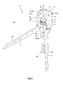
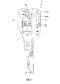
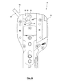
- the crimping tool 1 is formed in an A-shaped design, wherein the two downwardly facing limbs of the A of relatively pivotable hand levers 2, 3 are formed, while the remaining part of the A from an annular front view in the frame 4 with a recess 5 is formed is. In the region of the recess 4, the interaction takes place of two pressing jaws 6, 7 associated with dies 8, 9 with a workpiece 10, which is a connector 93 with cable 78 for a solar connector 90 here.
- the crimping tool 1 is here created largely in panel construction. Suitable parts are hereby designed as flat plates which can be easily stamped, milled or produced by grinding.
- a crimping tool head 11 forming the frame 4 is formed with two cover plates 12 on which or between which further components of the crimping tool 1 are mounted, supported or guided, as will be described below.
- the cover plates 12 With here integrally formed by the cover plates 12 extensions 13 and the extensions 13 receiving plastic handle 14 is a solid, not relative to the crimping pliers head 11 moving hand lever 2 is formed.
- the extensions 13 On the hand lever 2, here the extensions 13, a Abisolier driving 15 is permanently or detachably held for cables of different diameters or with several layers.
- an actuating surface of the hand lever 3 comes to rest against the stripping tool 15.
- An actuating force generated during the closing movement of the hand lever 2, 3 thus actuates the stripping tool 15.
- For connecting the stripping device 15, embodiment thereof and actuation of the stripping device 15 Closure of the hand lever 2, 3 is on the Patent Application EP 2 305 428 A1 directed.
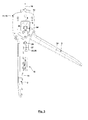
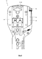
- the drive mechanism for the pressing jaw 7 is formed as follows:
- the pressing jaw 7 is formed to a first approximation T-shaped, wherein in the region of a transverse leg 20 of the T, the die 9 is fixed to the pressing jaw 7.
- a longitudinal leg 21 of the T has two spaced guide pins 22, 23, which transverse to the plane of the pressing jaw 7 and a crimping tool head plane 24 which parallel to the plane according to Fig. 1 is oriented, oriented.
- the guide pins 22, 23 are rigidly coupled to the pressing jaw 7.
- Both connecting portions of the guide pins 22, 23 and the guide slots 26, 27 are arranged coaxially with the crimping direction 16, so that the pressing jaw 7 exclusively a movement can perform in the direction of Crimpides 16, a transverse movement is limited or prevented and tilting in view of the distance between the guide pins 22, 23 is reliably avoided.
- the position and length of the guide slots 26, 27 is herbei determined such that the pressing jaw 7 can perform the required pressing stroke between the open position of the pressing jaw 7 and the end position of the pressing jaw 7.
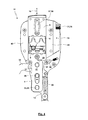
- a toggle lever drive 35 is thus formed with the pivot bearing of the toggle lever 30 formed by the bearing pin 28 with respect to the cover plates 12, the toggle lever 30, the knee joint 31, the toggle 32 and the pivot joint formed by the guide pin 22 between the toggle lever 32 and the pressing jaw 7.
- a pivoting of the hand lever 3 and the extension 33 in Fig. 5 inward on the hand lever 2 has the consequence that the "knee is stretched", so the angle between the toggle levers 30, 32 is increased in the direction of the extended position, bringing the distance between the bearing pin 28 of the Guide pin 22 and thus ultimately the die 9 increases.
- the said pivoting of the hand lever 3 in the direction of the hand lever 2 thus has the movement of the pressing jaw 7 upwards.
- the bearing pin 28 passes through a recess 36, here a slot, the pressing jaw 7.
- the toggle lever 30 is formed as a toggle lever tab with lugs or extensions 37, 38.
- a Federfußddling a biased under some circumstances compression spring 39 from.
- the other spring base of the compression spring 39 is supported on the hand lever 2 or the extension 13.
- the compression spring 39 causes a restoring moment, which the toggle lever 30 about the bearing pin 28 in Fig. 5 counteracted in the counterclockwise direction, whereby the hand lever 3 are applied to the outside in the open position and the pressing jaw 7 down to the open position, so that these positions are taken automatically, unless otherwise takes place an application of forces or a Zwangsgesperre 40 acts.
- the Zwangsgesperre 40 is formed with a toothed circumferential segment 41, which is formed by the extension 37.
- the toothed circumferential segment 41 interacts with a pawl 42, which consists of the in Fig. 5 shown position under the action of a spring in both directions can be pivoted.
- the pawl 42 is first counterclockwise in Fig. 5 twisted.
- the interaction between the pawl 42 and the gear perimeter segment 41 results in the pawl 42 "ratcheting" along the gear perimeter segment 41 during the closing movement of the hand levers 2, 3.
- the engagement of the pawl 42 in the toothed circumferential segment 41 prevents the undesired opening movement of the hand lever. Only when the pressing stroke has passed completely, ie the hand lever 2, 3 are completely closed, the pawl 42 has left the toothed peripheral segment 41 again. In a movement of the hand lever 2, 3 apart, which can be brought about by the actuating forces of the user or the compression spring 39, then the pawl 42 on the equilibrium position according to Fig. 5 further rotated in a clockwise direction. The interaction of the pawl 42 with the girth circumferential segment 41 is now such that the opening movement is not blocked. Rather, the pawl 42 slides along the toothed circumferential segment 41, until again the open position according to Fig. 5 is reached.
- Fig. 4 It can be seen that the pressing jaw 7 is guided in the region of the transverse limb 20 (in addition to the guidance explained by the guide pins 22, 23 in the guide slots 26, 27) between two guide rods 43, 44.
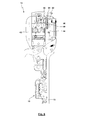
- the drive mechanism for the pressing jaw 6 with associated die 8 is formed as follows:
- the pressing jaw 6 is likewise guided between the guide rods 43, 44 such that it has only one degree of freedom in the crimping direction 16.
- Accessible from the outside on the crimping tool head 11 is the actuating impeller 18, via which, depending on the position of the actuating impeller 18, the pressing jaw 6 can be moved up and down by means of the actuating mechanism.
- the actuating impeller 18 is rotatably connected to an opposite the cover plates 12 mounted actuating shaft 45. Between the cover plates 12, a kind of crank 46 is rotatably mounted on the actuating shaft 45.
- a compression spring 50 acts on the pressing jaw 6 in Crimpides 16 away from the pressing jaw 7, including the compression spring 50 preferably also in the insertion position according to Fig. 6 is biased.
- a spring base of the compression spring 50 is supported by a pin 51 on the pressing jaw 6, while the other spring base of the compression spring 50 is supported on the cover plates 12, here on the guide rod 44.
- grooves 52 are introduced into the guide surfaces of the guide rods 43, 44 for the pressing jaw. In the grooves 52, the pin 51 can be performed and / or the compression spring 50 can be added to save space, in which case a Federfußyak the compression spring 50 is supported on an end portion of the groove 52.
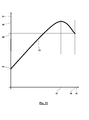
- a characteristic 53 for the actuation of the actuating device 19 is shown.
- Applied here is the force 54 in the compression spring 50 on the rotation angle 55 of the Actuating impeller 18 and the crank 46, starting from the insertion position according to Fig. 6 when rotated clockwise.
- the force in the compression spring 50 due to the bias is not equal to zero.
- an edge 56 of the crank 46 comes to rest on the actuating surface 47 of the pressing jaw.
- the increase in the angle of rotation 55 has an increase in the bias of the compression spring 50 result.
- the force 54 of the compression spring 50 has reached a maximum 58.
- a movement outside the angular range of 0 ° to 90 ° can be avoided by stops.
- Such a characteristic 53 has the consequence that the user is given a haptic feedback during the rotation of the actuation impeller 18. If the user overcomes the maximum 58, the crank 46 "snaps" under the assistance of the compression spring 50 in the crimping position (or in reverse rotation in the insertion position) under certain circumstances. Under certain circumstances, this can even audibly lead to a "clack" when the crank 46 comes with its front side 49 to bear against the actuating surface 47. It is understood that, unlike the example selected contour of the crank 46 can find any contour design use.
- a cam disc can be used, by means of which the change in the position of the pressing jaw 6 via a rotation of the actuating impeller 18 via a different angle than 90 °, wherein on the contour of the cam disc further possibilities for influencing the Characteristic 53 are given.
- both the insertion position (rotation angle 55 of 0 °) and the crimping position (rotation angle 55 of 90 °) are stably formed.
- the compression spring 50 is acted upon by the crank with a predetermined by the contour of the crank 46 non-linearity.
- Fig. 12 schematically shows an alternative actuating mechanism and an alternative manual actuator 19 for causing a movement of the pressing jaw 6 between an insertion position and a crimping position.
- the actuator 19 formed with a toggle lever 62.
- the toggle lever drive 62 has a first toggle lever 63, which is articulated in an end region in a pivot bearing 64 on the cover plates 12.
- the other end region of the toggle lever 63 is articulated via a knee joint 65 to a second toggle lever 66.
- the knee lever 66 is in turn articulated via a pivot bearing 67 on the pressing jaw 6.
- the toggle 66 is extended beyond the knee joint 65, thus forming an operating lever 68 accessible from the outside.
- the user can apply pivoting forces on the actuating lever 68, which act on the toggle lever drive 62 in the direction of the extended position, whereby a movement from the insertion position in the direction of the crimping position can be caused.
- Fig. 13 shows an alternative embodiment of an actuator 19.
- the actuator 19 is formed with a contour cross slide 69, which can be moved by the user across the Crimpcardi 16.
- effective position of the contour cross slide 69 has a greater extension in Crimpcardi 16, so that here the pressing jaw 6 is further displaced in the direction of the pressing jaw 7.
- a transverse displacement of the contour cross slide 69 causes the actuating surface 47 of the pressing jaw 6 to abut and be supported on a partial region of the contour cross slide 69, which is arranged further away from the pressing jaw 7 in the crimping direction 16.
- the contour cross slide 69 need not necessarily be formed with steps as shown. Rather, any curved, straight piece or stepped contour can be used here.
- Fig. 14 shows an alternative embodiment of the actuator 19, for which via an actuator 17, for example, an actuating impeller 18, a gear 70 is rotated, which meshes with a rack 71, which is oriented parallel to Crimpcardi 16 and preferably secured laterally on the pressing jaw 7 is.
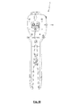
- the crimping tool 1 according to the illustrated embodiments, a positioning device 72. While this positioning device 72 may in principle be arranged at any point, for example also in the region of the hand lever 2, 3 on its inner sides, the positioning device 72 is arranged in the region of the crimping tool head 11 for the illustrated exemplary embodiments. According to Fig. 4 the positioning device is received in the lateral edge region between the two cover plates 12.
- the positioning device 72 is made of plastic.
- the positioning device is held by screws or pins 73 on the guide rod 44.
- the positioning device 72 forms a chamber 74, the longitudinal extent of which is oriented parallel to the crimping direction 16.
- the chamber 74 is bounded in the lower end region by a transverse wall 75, which forms a contact surface 85 on the side facing into the chamber.
- the chamber 74 is open.
- the chamber 74 is also open on the side facing away from the guide rod 44, outwardly oriented side.
- a first component 76 can be inserted, on or at which a second component 77 is to be arranged at a defined position.
- the first component 76 is a cable 78, while the second component 77 is a pushed onto the cable 78 seal 79.
- Cable 78 and seal 79 are intended to connect to a plug 93 in an end region 80 by means of the crimping tool 1 after removal of an insulation in the end region 80, in particular by means of Abisolier owned 15.
- the cable 78, the seal 79 and the plug 93 are inserted into a plug housing 89, wherein the seal 79 is to ensure a seal between the cable 78 and connector housing 89 (see. Fig. 17 ).
- Such embodiments are used, for example, for solar connectors for solar modules.
- the positioning device 72 has a receptacle 81, which can accurately fit the component 77, in particular the seal 79.
- the receptacle 81 has an axial contact surface 82 and a lateral contact surface 83.
- the seal 79 is an end face of the seal 79 for contact with the contact surface 82, whereby the axial position of the seal 79 relative to the positioning 72 is predetermined. Then, the seal 79 can be pressed against the contact surface 82, that a position and orientation of the seal 79 is exactly predetermined transversely to the axial direction. Extends, as in Fig.
- the position of the seal 79 on the cable 78 is adjusted so that the end face of the end portion 80 just bears against the contact surface 85. This can be done outside of the positioning device 72 with repeated successive insertion of cable 78 with seal 79 in the positioning 72 or by the cable 78 is pushed or pulled into position while the seal 79 is in the receptacle 81.
- the positioning device 72 is formed with a plate-shaped base body 86 in a first approximation, from which the pins 73 extend.
- the main body 86 comes to a large area to rest on the guide rod 44th In the in Fig. 16
- Upper end portion of the base body 86 forms by corresponding recesses, formations or cutouts the receptacle 81.
- the chamber 74 which is open in the direction of the receptacle 81, is delimited by the abutment surface 85 or transverse wall 75, while it is bounded laterally by side walls 87, 88.
- the side walls 87, 88 have a spacing correlating with the cable to be inserted into the chamber 74.
- the chamber 74 is rounded off with a radius which correlates with the radius of the cable to be inserted into the chamber 74.
- the positioning 72 may be permanently attached to the crimping tool 11, be retrofitted or be clipped with the crimping tool 11. It is possible that various positioning devices 72, for example, for different seals, cables, predetermined distances u. ⁇ . Replaceable with the crimper 11 are connectable. It is understood that the positioning 72 may be provided at any point on the crimping tool 1 deviating from the illustrated embodiments.
- the pressing tongs 1 is equipped with a locator 84, as this example in DE 198 32 884 C1 .
- DE 20 2008 033 703 U1 and DE 10 2010 061 148 A1 in greater detail for different, also usable embodiments is described.
- Fig. 17 shows exemplary and highly schematic of a solar connector 90.
- the solar connector 90 is formed with the cable 78, on which, using the positioning device 72 at a defined distance 91 from a front side 92, the seal 79 is arranged.
- the distance 91 corresponds to the distance of the contact surface 85 from the receptacle 81 of the positioning device 72.
- the end portion of the cable has been stripped by the Abisolier owned 15.
- a plug 93 is then crimped onto the stripped end of the cable 78.
- the connector housing 89 mounted on the seal 79, the cable 78 and the plug 93, wherein a detent 94 engages behind the plug 93.
- the seal 79 is in the in Fig. 17 illustrated assembled position of the solar connector 90 such between the cable 78 and connector housing 89 radially braced that a seal is ensured and a predetermined tensile load on the cable 78 is received frictionally.
- the plug housing 89 is formed in a manner not shown for the positive or frictional or latching connection with a counter plug housing, wherein the connection of the plug housing 89 with the counter plug housing and an electrical contact of a mating connector ensured with the plug 93.
Landscapes
- Engineering & Computer Science (AREA)
- Manufacturing & Machinery (AREA)
- Manufacturing Of Electrical Connectors (AREA)
Priority Applications (1)
| Application Number | Priority Date | Filing Date | Title |
|---|---|---|---|
| EP12170860.6A EP2672580B1 (fr) | 2012-06-05 | 2012-06-05 | Tête de pince de sertissage |
Applications Claiming Priority (1)
| Application Number | Priority Date | Filing Date | Title |
|---|---|---|---|
| EP12170860.6A EP2672580B1 (fr) | 2012-06-05 | 2012-06-05 | Tête de pince de sertissage |
Publications (2)
| Publication Number | Publication Date |
|---|---|
| EP2672580A1 true EP2672580A1 (fr) | 2013-12-11 |
| EP2672580B1 EP2672580B1 (fr) | 2017-02-01 |
Family
ID=46245877
Family Applications (1)
| Application Number | Title | Priority Date | Filing Date |
|---|---|---|---|
| EP12170860.6A Active EP2672580B1 (fr) | 2012-06-05 | 2012-06-05 | Tête de pince de sertissage |
Country Status (1)
| Country | Link |
|---|---|
| EP (1) | EP2672580B1 (fr) |
Cited By (15)
| Publication number | Priority date | Publication date | Assignee | Title |
|---|---|---|---|---|
| EP2995424A1 (fr) | 2014-09-11 | 2016-03-16 | Wezag GmbH Werkzeugfabrik | Pince |
| DE202014011110U1 (de) | 2014-09-11 | 2017-11-29 | Wezag Gmbh Werkzeugfabrik | Handzange |
| DE202016105959U1 (de) | 2016-10-24 | 2018-01-25 | Wezag Gmbh Werkzeugfabrik | Crimpwerkzeug-Positionierer, Crimpwerkzeugkopf und Crimpwerkzeug |
| EP3300187A1 (fr) | 2016-09-22 | 2018-03-28 | Wezag GmbH Werkzeugfabrik | Positionneur d'outil de presse et outil de presse |
| EP3309915A1 (fr) | 2016-10-14 | 2018-04-18 | Wezag GmbH Werkzeugfabrik | Pince à dénuder, couteau à dénuder, et procédé de dénudage |
| EP3312949A1 (fr) | 2016-10-24 | 2018-04-25 | Wezag GmbH Werkzeugfabrik | Crimpwerkzeug-positionierer, crimpwerkzeugkopf, crimpwerkzeug und verfahren zur herstellung eines crimpwerkzeug-positionierers |
| EP3396796A1 (fr) | 2017-04-25 | 2018-10-31 | Wezag GmbH Werkzeugfabrik | Outil de compression, de sertissage ou de découpe et module d'outils |
| CN110854645A (zh) * | 2019-10-23 | 2020-02-28 | 石鑫 | 一种电力施工使用的接线装置 |
| EP3820001A1 (fr) | 2019-11-11 | 2021-05-12 | WEZAG GmbH & Co. KG | Pince à sertir, groupe de pinces à sertir et utilisation d'une moitié de matrice |
| EP3834989A1 (fr) | 2019-12-11 | 2021-06-16 | WEZAG GmbH & Co. KG | Outil pince à main et procédé de montage d'un tel outil |
| CN114361902A (zh) * | 2020-10-12 | 2022-04-15 | 北京开元浩海科技发展有限公司 | 一种电力手动液压钳 |
| WO2022038186A3 (fr) * | 2020-08-20 | 2022-05-05 | Rennsteig Werkzeuge Gmbh | Pince manuelle conçue pour réaliser un sertissage et pince manuelle pourvue d'une tête de pince |
| CN115792563A (zh) * | 2022-11-07 | 2023-03-14 | 武汉精毅通电子技术有限公司 | 一种cell产品的多工位压接治具及测试设备 |
| EP4243222A1 (fr) | 2022-03-09 | 2023-09-13 | WEZAG GmbH & Co. KG | Capteur de puissance de pince à sertir et pince à sertir |
| RU2835722C1 (ru) * | 2020-08-20 | 2025-03-03 | Реннштайг Веркцойге Гмбх | Ручные клещи для обжатия |
Citations (4)
| Publication number | Priority date | Publication date | Assignee | Title |
|---|---|---|---|---|
| US5012666A (en) * | 1989-07-24 | 1991-05-07 | Chen Ching Wen | Crimp tool with adjustable jaw |
| US20030066186A1 (en) * | 2001-10-04 | 2003-04-10 | Hanlong Ind. Co., Ltd. | Co-axial terminator press fitting pliers |
| EP1496580A1 (fr) * | 2003-07-05 | 2005-01-12 | Weidmüller Interface GmbH & Co. KG | Pince à sertir |
| EP2107650A2 (fr) * | 2008-04-04 | 2009-10-07 | Wezag GmbH Werkzeugfabrik | Pince de serrage dotée d'un positionneur |
-
2012
- 2012-06-05 EP EP12170860.6A patent/EP2672580B1/fr active Active
Patent Citations (4)
| Publication number | Priority date | Publication date | Assignee | Title |
|---|---|---|---|---|
| US5012666A (en) * | 1989-07-24 | 1991-05-07 | Chen Ching Wen | Crimp tool with adjustable jaw |
| US20030066186A1 (en) * | 2001-10-04 | 2003-04-10 | Hanlong Ind. Co., Ltd. | Co-axial terminator press fitting pliers |
| EP1496580A1 (fr) * | 2003-07-05 | 2005-01-12 | Weidmüller Interface GmbH & Co. KG | Pince à sertir |
| EP2107650A2 (fr) * | 2008-04-04 | 2009-10-07 | Wezag GmbH Werkzeugfabrik | Pince de serrage dotée d'un positionneur |
Cited By (25)
| Publication number | Priority date | Publication date | Assignee | Title |
|---|---|---|---|---|
| DE202014011110U1 (de) | 2014-09-11 | 2017-11-29 | Wezag Gmbh Werkzeugfabrik | Handzange |
| US9864948B2 (en) | 2014-09-11 | 2018-01-09 | Wezag Gmbh Werkzeugfabrik | Hand pliers |
| EP2995424A1 (fr) | 2014-09-11 | 2016-03-16 | Wezag GmbH Werkzeugfabrik | Pince |
| US11381048B2 (en) | 2016-09-22 | 2022-07-05 | Wezag Gmbh & Co. Kg | Crimping tool locator and crimping tool |
| EP3300187A1 (fr) | 2016-09-22 | 2018-03-28 | Wezag GmbH Werkzeugfabrik | Positionneur d'outil de presse et outil de presse |
| US10355461B2 (en) | 2016-10-14 | 2019-07-16 | Wezag Gmbh Werkzeugfabrik | Stripping tool and method for stripping |
| EP3309915A1 (fr) | 2016-10-14 | 2018-04-18 | Wezag GmbH Werkzeugfabrik | Pince à dénuder, couteau à dénuder, et procédé de dénudage |
| EP3312949A1 (fr) | 2016-10-24 | 2018-04-25 | Wezag GmbH Werkzeugfabrik | Crimpwerkzeug-positionierer, crimpwerkzeugkopf, crimpwerkzeug und verfahren zur herstellung eines crimpwerkzeug-positionierers |
| DE202016105959U1 (de) | 2016-10-24 | 2018-01-25 | Wezag Gmbh Werkzeugfabrik | Crimpwerkzeug-Positionierer, Crimpwerkzeugkopf und Crimpwerkzeug |
| EP3396796A1 (fr) | 2017-04-25 | 2018-10-31 | Wezag GmbH Werkzeugfabrik | Outil de compression, de sertissage ou de découpe et module d'outils |
| US10958030B2 (en) | 2017-04-25 | 2021-03-23 | Wezag Gmbh Werkzeugfabrik | Jaw tool and jaw tool group |
| CN110854645A (zh) * | 2019-10-23 | 2020-02-28 | 石鑫 | 一种电力施工使用的接线装置 |
| EP3820001A1 (fr) | 2019-11-11 | 2021-05-12 | WEZAG GmbH & Co. KG | Pince à sertir, groupe de pinces à sertir et utilisation d'une moitié de matrice |
| US11346732B2 (en) | 2019-11-11 | 2022-05-31 | Wezag Gmbh & Co. Kg | Crimping pliers, group of crimping pliers and use of a die half |
| EP4007087A1 (fr) | 2019-11-11 | 2022-06-01 | WEZAG GmbH & Co. KG | Pince à sertir |
| EP3834989A1 (fr) | 2019-12-11 | 2021-06-16 | WEZAG GmbH & Co. KG | Outil pince à main et procédé de montage d'un tel outil |
| US12015233B2 (en) | 2019-12-11 | 2024-06-18 | Wezag Gmbh & Co. Kg | Hand pliers tool and method for assembling the same |
| WO2022038186A3 (fr) * | 2020-08-20 | 2022-05-05 | Rennsteig Werkzeuge Gmbh | Pince manuelle conçue pour réaliser un sertissage et pince manuelle pourvue d'une tête de pince |
| RU2835722C1 (ru) * | 2020-08-20 | 2025-03-03 | Реннштайг Веркцойге Гмбх | Ручные клещи для обжатия |
| TWI891884B (zh) * | 2020-08-20 | 2025-08-01 | 德商雷恩斯坦格工具公司 | 用於實施壓接的手鉗 |
| CN114361902A (zh) * | 2020-10-12 | 2022-04-15 | 北京开元浩海科技发展有限公司 | 一种电力手动液压钳 |
| CN114361902B (zh) * | 2020-10-12 | 2024-04-30 | 北京开元浩海科技发展有限公司 | 一种电力手动液压钳 |
| EP4243222A1 (fr) | 2022-03-09 | 2023-09-13 | WEZAG GmbH & Co. KG | Capteur de puissance de pince à sertir et pince à sertir |
| US12492952B2 (en) | 2022-03-09 | 2025-12-09 | Wezag Gmbh & Co. Kg | Force sensors for crimping pliers and crimping pliers comprising a force sensor |
| CN115792563A (zh) * | 2022-11-07 | 2023-03-14 | 武汉精毅通电子技术有限公司 | 一种cell产品的多工位压接治具及测试设备 |
Also Published As
| Publication number | Publication date |
|---|---|
| EP2672580B1 (fr) | 2017-02-01 |
Similar Documents
| Publication | Publication Date | Title |
|---|---|---|
| EP2672580B1 (fr) | Tête de pince de sertissage | |
| EP2463969B1 (fr) | Tête de pince pour une pince de sertissage | |
| EP2873122B1 (fr) | Outil de sertissage pour douille d'extrêmité de conducteur | |
| EP3012923B1 (fr) | Pince de pression | |
| DE19963097C5 (de) | Zange zum Verpressen eines Werkstücks | |
| EP2562891B1 (fr) | Pince de pression | |
| EP2305428B1 (fr) | Pince | |
| EP3159088B1 (fr) | Pince manuelle | |
| EP2107650B1 (fr) | Pince de serrage dotée d'un positionneur | |
| EP3614507B1 (fr) | Pinces à presser ou à sertir | |
| EP2096725A1 (fr) | Tête pince | |
| DE202008005083U1 (de) | Presszange | |
| DE19924086A1 (de) | Zange zum Verpressen von Fassungen, Rohren, Kabelschuhen und dgl. | |
| EP2905848A1 (fr) | Pince de pression | |
| EP3718179A1 (fr) | Pince-étau | |
| DE102018121971A1 (de) | Presswerkzeug | |
| EP2078591B1 (fr) | Outil de presse | |
| EP2672581A1 (fr) | Pince de sertissage pour connecteur solaire avec aide au positionnement | |
| EP4200946B1 (fr) | Pince manuelle conçue pour réaliser un sertissage et pince manuelle pourvue d'une tête de pince | |
| WO2016008625A1 (fr) | Outil pour dénuder un câble | |
| EP2385891B1 (fr) | Pince destinée à l'assemblage par manchon coulissant | |
| DE102009044925B4 (de) | Handwerkzeug und Handwerkzeug-Set | |
| EP4560849B1 (fr) | Outil, plaquette d'outil et groupe d'outils | |
| DE2521378B2 (de) | Zange zum verpressen von kabelverbindern (crimp-werkzeug) | |
| EP0924817B1 (fr) | Pince à sertir, mors pour cette pince, et procédé de manipulation de celle-ci |
Legal Events
| Date | Code | Title | Description |
|---|---|---|---|
| PUAI | Public reference made under article 153(3) epc to a published international application that has entered the european phase |
Free format text: ORIGINAL CODE: 0009012 |
|
| AK | Designated contracting states |
Kind code of ref document: A1 Designated state(s): AL AT BE BG CH CY CZ DE DK EE ES FI FR GB GR HR HU IE IS IT LI LT LU LV MC MK MT NL NO PL PT RO RS SE SI SK SM TR |
|
| AX | Request for extension of the european patent |
Extension state: BA ME |
|
| 17P | Request for examination filed |
Effective date: 20140517 |
|
| RBV | Designated contracting states (corrected) |
Designated state(s): AL AT BE BG CH CY CZ DE DK EE ES FI FR GB GR HR HU IE IS IT LI LT LU LV MC MK MT NL NO PL PT RO RS SE SI SK SM TR |
|
| GRAP | Despatch of communication of intention to grant a patent |
Free format text: ORIGINAL CODE: EPIDOSNIGR1 |
|
| INTG | Intention to grant announced |
Effective date: 20161014 |
|
| GRAS | Grant fee paid |
Free format text: ORIGINAL CODE: EPIDOSNIGR3 |
|
| GRAA | (expected) grant |
Free format text: ORIGINAL CODE: 0009210 |
|
| AK | Designated contracting states |
Kind code of ref document: B1 Designated state(s): AL AT BE BG CH CY CZ DE DK EE ES FI FR GB GR HR HU IE IS IT LI LT LU LV MC MK MT NL NO PL PT RO RS SE SI SK SM TR |
|
| REG | Reference to a national code |
Ref country code: GB Ref legal event code: FG4D Free format text: NOT ENGLISH |
|
| REG | Reference to a national code |
Ref country code: CH Ref legal event code: EP Ref country code: AT Ref legal event code: REF Ref document number: 866266 Country of ref document: AT Kind code of ref document: T Effective date: 20170215 |
|
| REG | Reference to a national code |
Ref country code: IE Ref legal event code: FG4D Free format text: LANGUAGE OF EP DOCUMENT: GERMAN |
|
| REG | Reference to a national code |
Ref country code: DE Ref legal event code: R096 Ref document number: 502012009418 Country of ref document: DE |
|
| REG | Reference to a national code |
Ref country code: NL Ref legal event code: MP Effective date: 20170201 |
|
| REG | Reference to a national code |
Ref country code: LT Ref legal event code: MG4D |
|
| REG | Reference to a national code |
Ref country code: FR Ref legal event code: PLFP Year of fee payment: 6 |
|
| PG25 | Lapsed in a contracting state [announced via postgrant information from national office to epo] |
Ref country code: GR Free format text: LAPSE BECAUSE OF FAILURE TO SUBMIT A TRANSLATION OF THE DESCRIPTION OR TO PAY THE FEE WITHIN THE PRESCRIBED TIME-LIMIT Effective date: 20170502 Ref country code: HR Free format text: LAPSE BECAUSE OF FAILURE TO SUBMIT A TRANSLATION OF THE DESCRIPTION OR TO PAY THE FEE WITHIN THE PRESCRIBED TIME-LIMIT Effective date: 20170201 Ref country code: FI Free format text: LAPSE BECAUSE OF FAILURE TO SUBMIT A TRANSLATION OF THE DESCRIPTION OR TO PAY THE FEE WITHIN THE PRESCRIBED TIME-LIMIT Effective date: 20170201 Ref country code: NO Free format text: LAPSE BECAUSE OF FAILURE TO SUBMIT A TRANSLATION OF THE DESCRIPTION OR TO PAY THE FEE WITHIN THE PRESCRIBED TIME-LIMIT Effective date: 20170501 Ref country code: IS Free format text: LAPSE BECAUSE OF FAILURE TO SUBMIT A TRANSLATION OF THE DESCRIPTION OR TO PAY THE FEE WITHIN THE PRESCRIBED TIME-LIMIT Effective date: 20170601 Ref country code: LT Free format text: LAPSE BECAUSE OF FAILURE TO SUBMIT A TRANSLATION OF THE DESCRIPTION OR TO PAY THE FEE WITHIN THE PRESCRIBED TIME-LIMIT Effective date: 20170201 |
|
| PG25 | Lapsed in a contracting state [announced via postgrant information from national office to epo] |
Ref country code: SE Free format text: LAPSE BECAUSE OF FAILURE TO SUBMIT A TRANSLATION OF THE DESCRIPTION OR TO PAY THE FEE WITHIN THE PRESCRIBED TIME-LIMIT Effective date: 20170201 Ref country code: PL Free format text: LAPSE BECAUSE OF FAILURE TO SUBMIT A TRANSLATION OF THE DESCRIPTION OR TO PAY THE FEE WITHIN THE PRESCRIBED TIME-LIMIT Effective date: 20170201 Ref country code: BG Free format text: LAPSE BECAUSE OF FAILURE TO SUBMIT A TRANSLATION OF THE DESCRIPTION OR TO PAY THE FEE WITHIN THE PRESCRIBED TIME-LIMIT Effective date: 20170501 Ref country code: NL Free format text: LAPSE BECAUSE OF FAILURE TO SUBMIT A TRANSLATION OF THE DESCRIPTION OR TO PAY THE FEE WITHIN THE PRESCRIBED TIME-LIMIT Effective date: 20170201 Ref country code: PT Free format text: LAPSE BECAUSE OF FAILURE TO SUBMIT A TRANSLATION OF THE DESCRIPTION OR TO PAY THE FEE WITHIN THE PRESCRIBED TIME-LIMIT Effective date: 20170601 Ref country code: LV Free format text: LAPSE BECAUSE OF FAILURE TO SUBMIT A TRANSLATION OF THE DESCRIPTION OR TO PAY THE FEE WITHIN THE PRESCRIBED TIME-LIMIT Effective date: 20170201 Ref country code: RS Free format text: LAPSE BECAUSE OF FAILURE TO SUBMIT A TRANSLATION OF THE DESCRIPTION OR TO PAY THE FEE WITHIN THE PRESCRIBED TIME-LIMIT Effective date: 20170201 Ref country code: ES Free format text: LAPSE BECAUSE OF FAILURE TO SUBMIT A TRANSLATION OF THE DESCRIPTION OR TO PAY THE FEE WITHIN THE PRESCRIBED TIME-LIMIT Effective date: 20170201 |
|
| PG25 | Lapsed in a contracting state [announced via postgrant information from national office to epo] |
Ref country code: SK Free format text: LAPSE BECAUSE OF FAILURE TO SUBMIT A TRANSLATION OF THE DESCRIPTION OR TO PAY THE FEE WITHIN THE PRESCRIBED TIME-LIMIT Effective date: 20170201 Ref country code: CZ Free format text: LAPSE BECAUSE OF FAILURE TO SUBMIT A TRANSLATION OF THE DESCRIPTION OR TO PAY THE FEE WITHIN THE PRESCRIBED TIME-LIMIT Effective date: 20170201 Ref country code: RO Free format text: LAPSE BECAUSE OF FAILURE TO SUBMIT A TRANSLATION OF THE DESCRIPTION OR TO PAY THE FEE WITHIN THE PRESCRIBED TIME-LIMIT Effective date: 20170201 Ref country code: EE Free format text: LAPSE BECAUSE OF FAILURE TO SUBMIT A TRANSLATION OF THE DESCRIPTION OR TO PAY THE FEE WITHIN THE PRESCRIBED TIME-LIMIT Effective date: 20170201 |
|
| REG | Reference to a national code |
Ref country code: DE Ref legal event code: R097 Ref document number: 502012009418 Country of ref document: DE |
|
| PG25 | Lapsed in a contracting state [announced via postgrant information from national office to epo] |
Ref country code: SM Free format text: LAPSE BECAUSE OF FAILURE TO SUBMIT A TRANSLATION OF THE DESCRIPTION OR TO PAY THE FEE WITHIN THE PRESCRIBED TIME-LIMIT Effective date: 20170201 Ref country code: DK Free format text: LAPSE BECAUSE OF FAILURE TO SUBMIT A TRANSLATION OF THE DESCRIPTION OR TO PAY THE FEE WITHIN THE PRESCRIBED TIME-LIMIT Effective date: 20170201 |
|
| PLBE | No opposition filed within time limit |
Free format text: ORIGINAL CODE: 0009261 |
|
| STAA | Information on the status of an ep patent application or granted ep patent |
Free format text: STATUS: NO OPPOSITION FILED WITHIN TIME LIMIT |
|
| 26N | No opposition filed |
Effective date: 20171103 |
|
| PG25 | Lapsed in a contracting state [announced via postgrant information from national office to epo] |
Ref country code: MC Free format text: LAPSE BECAUSE OF FAILURE TO SUBMIT A TRANSLATION OF THE DESCRIPTION OR TO PAY THE FEE WITHIN THE PRESCRIBED TIME-LIMIT Effective date: 20170201 |
|
| REG | Reference to a national code |
Ref country code: CH Ref legal event code: PL |
|
| PG25 | Lapsed in a contracting state [announced via postgrant information from national office to epo] |
Ref country code: SI Free format text: LAPSE BECAUSE OF FAILURE TO SUBMIT A TRANSLATION OF THE DESCRIPTION OR TO PAY THE FEE WITHIN THE PRESCRIBED TIME-LIMIT Effective date: 20170201 |
|
| REG | Reference to a national code |
Ref country code: IE Ref legal event code: MM4A |
|
| PG25 | Lapsed in a contracting state [announced via postgrant information from national office to epo] |
Ref country code: LI Free format text: LAPSE BECAUSE OF NON-PAYMENT OF DUE FEES Effective date: 20170630 Ref country code: IE Free format text: LAPSE BECAUSE OF NON-PAYMENT OF DUE FEES Effective date: 20170605 Ref country code: CH Free format text: LAPSE BECAUSE OF NON-PAYMENT OF DUE FEES Effective date: 20170630 Ref country code: LU Free format text: LAPSE BECAUSE OF NON-PAYMENT OF DUE FEES Effective date: 20170605 |
|
| REG | Reference to a national code |
Ref country code: BE Ref legal event code: MM Effective date: 20170630 |
|
| REG | Reference to a national code |
Ref country code: FR Ref legal event code: PLFP Year of fee payment: 7 |
|
| REG | Reference to a national code |
Ref country code: AT Ref legal event code: MM01 Ref document number: 866266 Country of ref document: AT Kind code of ref document: T Effective date: 20170605 |
|
| PG25 | Lapsed in a contracting state [announced via postgrant information from national office to epo] |
Ref country code: BE Free format text: LAPSE BECAUSE OF NON-PAYMENT OF DUE FEES Effective date: 20170630 |
|
| PG25 | Lapsed in a contracting state [announced via postgrant information from national office to epo] |
Ref country code: MT Free format text: LAPSE BECAUSE OF FAILURE TO SUBMIT A TRANSLATION OF THE DESCRIPTION OR TO PAY THE FEE WITHIN THE PRESCRIBED TIME-LIMIT Effective date: 20170201 |
|
| PG25 | Lapsed in a contracting state [announced via postgrant information from national office to epo] |
Ref country code: AT Free format text: LAPSE BECAUSE OF NON-PAYMENT OF DUE FEES Effective date: 20170605 |
|
| PG25 | Lapsed in a contracting state [announced via postgrant information from national office to epo] |
Ref country code: HU Free format text: LAPSE BECAUSE OF FAILURE TO SUBMIT A TRANSLATION OF THE DESCRIPTION OR TO PAY THE FEE WITHIN THE PRESCRIBED TIME-LIMIT; INVALID AB INITIO Effective date: 20120605 |
|
| PG25 | Lapsed in a contracting state [announced via postgrant information from national office to epo] |
Ref country code: CY Free format text: LAPSE BECAUSE OF NON-PAYMENT OF DUE FEES Effective date: 20170201 |
|
| PG25 | Lapsed in a contracting state [announced via postgrant information from national office to epo] |
Ref country code: MK Free format text: LAPSE BECAUSE OF FAILURE TO SUBMIT A TRANSLATION OF THE DESCRIPTION OR TO PAY THE FEE WITHIN THE PRESCRIBED TIME-LIMIT Effective date: 20170201 |
|
| PG25 | Lapsed in a contracting state [announced via postgrant information from national office to epo] |
Ref country code: TR Free format text: LAPSE BECAUSE OF FAILURE TO SUBMIT A TRANSLATION OF THE DESCRIPTION OR TO PAY THE FEE WITHIN THE PRESCRIBED TIME-LIMIT Effective date: 20170201 |
|
| PG25 | Lapsed in a contracting state [announced via postgrant information from national office to epo] |
Ref country code: AL Free format text: LAPSE BECAUSE OF FAILURE TO SUBMIT A TRANSLATION OF THE DESCRIPTION OR TO PAY THE FEE WITHIN THE PRESCRIBED TIME-LIMIT Effective date: 20170201 |
|
| REG | Reference to a national code |
Ref country code: DE Ref legal event code: R082 Ref document number: 502012009418 Country of ref document: DE Representative=s name: REHBERG HUEPPE + PARTNER PATENTANWAELTE PARTG , DE Ref country code: DE Ref legal event code: R081 Ref document number: 502012009418 Country of ref document: DE Owner name: WEZAG GMBH & CO. KG, DE Free format text: FORMER OWNER: WEZAG GMBH WERKZEUGFABRIK, 35260 STADTALLENDORF, DE |
|
| PGFP | Annual fee paid to national office [announced via postgrant information from national office to epo] |
Ref country code: DE Payment date: 20250402 Year of fee payment: 14 |
|
| PGFP | Annual fee paid to national office [announced via postgrant information from national office to epo] |
Ref country code: GB Payment date: 20250620 Year of fee payment: 14 |
|
| PGFP | Annual fee paid to national office [announced via postgrant information from national office to epo] |
Ref country code: FR Payment date: 20250626 Year of fee payment: 14 |
|
| PGFP | Annual fee paid to national office [announced via postgrant information from national office to epo] |
Ref country code: IT Payment date: 20250630 Year of fee payment: 14 |