EP2107650A2 - Pince de serrage dotée d'un positionneur - Google Patents
Pince de serrage dotée d'un positionneur Download PDFInfo
- Publication number
- EP2107650A2 EP2107650A2 EP09155540A EP09155540A EP2107650A2 EP 2107650 A2 EP2107650 A2 EP 2107650A2 EP 09155540 A EP09155540 A EP 09155540A EP 09155540 A EP09155540 A EP 09155540A EP 2107650 A2 EP2107650 A2 EP 2107650A2
- Authority
- EP
- European Patent Office
- Prior art keywords
- positioner
- arm
- pliers
- pressing
- hand
- Prior art date
- Legal status (The legal status is an assumption and is not a legal conclusion. Google has not performed a legal analysis and makes no representation as to the accuracy of the status listed.)
- Granted
Links
- 238000002788 crimping Methods 0.000 claims abstract description 25
- 238000003825 pressing Methods 0.000 claims description 69
- 239000002184 metal Substances 0.000 claims description 10
- 230000001154 acute effect Effects 0.000 claims description 3
- 238000012546 transfer Methods 0.000 claims description 2
- 230000003213 activating effect Effects 0.000 abstract 4
- 239000004020 conductor Substances 0.000 description 12
- 210000003811 finger Anatomy 0.000 description 6
- 238000000034 method Methods 0.000 description 4
- 229910000831 Steel Inorganic materials 0.000 description 3
- 238000010276 construction Methods 0.000 description 3
- 238000003780 insertion Methods 0.000 description 3
- 230000037431 insertion Effects 0.000 description 3
- 238000009413 insulation Methods 0.000 description 3
- 239000010959 steel Substances 0.000 description 3
- 210000003813 thumb Anatomy 0.000 description 3
- 210000000617 arm Anatomy 0.000 description 2
- 230000001419 dependent effect Effects 0.000 description 2
- 238000013461 design Methods 0.000 description 2
- 238000005553 drilling Methods 0.000 description 2
- 238000009434 installation Methods 0.000 description 2
- 238000003754 machining Methods 0.000 description 2
- 238000000465 moulding Methods 0.000 description 2
- 238000010137 moulding (plastic) Methods 0.000 description 2
- OIRDTQYFTABQOQ-UHTZMRCNSA-N Vidarabine Chemical compound C1=NC=2C(N)=NC=NC=2N1[C@@H]1O[C@H](CO)[C@@H](O)[C@@H]1O OIRDTQYFTABQOQ-UHTZMRCNSA-N 0.000 description 1
- 230000002411 adverse Effects 0.000 description 1
- 230000000903 blocking effect Effects 0.000 description 1
- 238000006243 chemical reaction Methods 0.000 description 1
- 150000001875 compounds Chemical class 0.000 description 1
- 238000011161 development Methods 0.000 description 1
- 230000018109 developmental process Effects 0.000 description 1
- 230000000694 effects Effects 0.000 description 1
- 230000008030 elimination Effects 0.000 description 1
- 238000003379 elimination reaction Methods 0.000 description 1
- 210000005224 forefinger Anatomy 0.000 description 1
- 230000000977 initiatory effect Effects 0.000 description 1
- 238000002955 isolation Methods 0.000 description 1
- 238000004519 manufacturing process Methods 0.000 description 1
- 238000012545 processing Methods 0.000 description 1
- 210000002023 somite Anatomy 0.000 description 1
Images


Classifications
-
- H—ELECTRICITY
- H01—ELECTRIC ELEMENTS
- H01R—ELECTRICALLY-CONDUCTIVE CONNECTIONS; STRUCTURAL ASSOCIATIONS OF A PLURALITY OF MUTUALLY-INSULATED ELECTRICAL CONNECTING ELEMENTS; COUPLING DEVICES; CURRENT COLLECTORS
- H01R43/00—Apparatus or processes specially adapted for manufacturing, assembling, maintaining, or repairing of line connectors or current collectors or for joining electric conductors
- H01R43/04—Apparatus or processes specially adapted for manufacturing, assembling, maintaining, or repairing of line connectors or current collectors or for joining electric conductors for forming connections by deformation, e.g. crimping tool
- H01R43/042—Hand tools for crimping
Definitions
- the invention relates to a pressing tongs with a positioner according to the preamble of patent claim 1.
- Generic pressing tongs are used for pressing a workpiece in a tool arranged in a pliers head.
- crimping tool which is used in particular for pressing a connector or contact with a partially stripped conductor end.
- the pressing tongs can also be designed as working tongs, with which a plastic deformation of the workpiece is produced or a part of the workpiece is cut off or punched out.
- a generic pressing tongs equipped with a positioner which is also referred to as a "locator”. Such a positioner serves the functionally correct arrangement of the workpiece relative to the pressing tongs, in particular to the at least one tool.
- the positioner can ensure that with the beginning of the pressing operation, the workpiece is positioned correctly relative to the tool, for example, the connector is in the correct position relative to the stripped conductor end and / or against the tool.
- the positioner can maintain or influence the relative position of the workpiece to the tool, for example during plastic deformation of the workpiece occurring.
- a positioner when using the crimping pliers in conjunction with relatively small workpieces, in which a positioning by hand through an opening of the pliers head through relative to the moving tool parts is difficult or no longer possible.
- the connector on the one hand and the stripped conductor end on the other hand must each be brought into a predetermined relative position to the tools, which are designed here as a crimp die.
- FIG. 1 Another pressing tongs, which in Fig. 1 is sold by the applicant under the type designation CS20KS.
- This pressing tongs also has a C-shaped, open to one side pliers head.
- a positioner is linearly guided on an axis fixed to the pliers head, which is oriented according to the lower horizontal leg of the C and is arranged in a plane parallel to the pliers head plane.
- the positioner can be driven via a pivotable lever mounted on the pliers head, the pivoting movement of which is converted via a connection between a pin guided in a slot into a linear movement along the axis for the linear movement of the positioner.
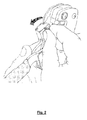
- a pressing pliers of the applicant with the type designation CS25KS is known in Fig. 2 is shown and has a C-shaped pliers head.
- a positioner is pivotally mounted about a pivot axis relative to the pliers head, which is oriented vertically to the pliers head plane.
- the positioner is pivotable about the rotation of a knurl in the pliers head plane between a plug-on position and a working position.
- the pivoting of the positioner is carried out in a two-handed operation, with one hand holding the crimping pliers in the range of the hand lever and the second hand causes a pivoting of the positioner.
- DE 198 32 884 C1 discloses a crimping pliers with a pliers head in a plate construction, which is not C-shaped with one-sided opening, but O-shaped without opening in the circumferential direction.
- a movable tool part is displaceable in the direction of a longitudinal axis relative to a pliers head fixed tool part.
- the document proposes a positioner, which is pivotable about a pivot axis, which is oriented parallel to the pliers head plane and transverse to the direction of movement of the tool parts of the pressing pliers. In a working position, the positioner is oriented substantially parallel to the pliers head plane. From this working position, the positioner can be swung out about the pivot axis in a Aufsteckwolf Berlin. For a pivoting of the positioner also a two-handed operation of the pressing tongs is required.
- the invention has for its object to provide a pressing tongs for pressing a workpiece whose operation is simplified.
- a positioner is used, which is pivotable relative to a pliers head about a pivot axis, which is oriented parallel to a pliers head plane and is oriented transversely to the direction of movement of tool parts of the pressing pliers.
- the positioner "can be swung out of the pliers head plane".
- a degree of freedom of the positioner allows the use of the positioner for non-C-shaped pliers heads, since the positioner does not have to be moved through the opening of the C in the course of relative movement to the pliers head, as in particular for the prior art according to DE 27 18 165 A1 and the pressing tongs of the applicant CS20KS and CS25KS is the case.
- the positioner is in operative connection with an actuating member, with the actuation of which a pivoting of the positioner relative to the pliers head can be brought about directly or indirectly.
- the actuating member is in this case designed and arranged such that it can be actuated by a hand of the user enclosing the hand lever of the pressing tongs.
- the actuator is formed with an arm or arm of the positioner, which allows easy connection and can be simple.
- the length and the course of the arm or Jib can be worn a particularly good feel or good operation options of the actuator account.
- such an arm can be formed with a metal sheet, which in particular can be bent, bent or twisted to bring about a desired geometry and suitable actuating surfaces.
- the arm or the sheet is multifunctional in the pressing tongs according to the invention, since this not only serves to apply a force or a moment for pivoting the positioner, but at the same time forms at least one Abstützort for a spring element.
- This spring element can serve to act on the positioner in the direction of a position, preferably the working position.
- the hand lever carry out a movement in a plane with the pressing stroke of the pressing tongs, which preferably corresponds to the tongs head plane or is oriented parallel thereto.
- the arm In the working position of the positioner, the arm forms an acute angle with respect to the aforementioned plane.
- the arm is pivoted in the direction of the plane. Such pivoting can be done for example by the index finger or middle finger of the pressing tongs holding hand.
- the positioner is preferably secured or securable in the working position via a latching device or a blocking device.
- a locking device is understood to mean a device which holds the positioner in the vicinity of the working position or in the latter itself for small-acting forces on the positioner and arm or extension arm, while the positioner can be moved away from the working position for forces acting in an enlarged manner.
- a latching device examples include a spring-loaded latching ball which engages in the working position in a corresponding latching groove, which can be specified via the diameter design of the detent ball, the geometry of the groove and the stiffness of the detent ball spring supporting the forces that are required move the positioner out of the working position. Accordingly, a locking pin can be used.
- a magnet as a latching device, wherein on the strength of the magnetic force, the latching force can be specified in the working position and an automatic closing movement can be brought about by a surrounding area of the working position.
- a locking device is understood to mean a device which can not be released merely by applying forces in the direction of the pivoting degree of freedom of the positioner. Rather, preferably in the locking device, a positive securing the working position with or without clearance, including, for example, a locking pin or a pawl can be used.
- the locking device can be released from the same hand or the second hand of the user or be solved by additional actuators or by movement of the actuator in the direction of another degree of freedom than the pivoting degree of freedom of the positioner. (Accordingly, it is within the scope of the invention also possible that the positioner is secured in a position deviating from the working position, for example, the plug-on position, via a locking device or a locking device or is securable.)
- a specification of a maximum pivot angle of the positioner relative to the pliers head is determined by the positioning of the positioner relative to the pliers head or other attacks
- the arm or boom in addition to the function of transmitting actuation forces and possibly the support of a spring element also serve to limit the maximum pivoting of the positioner. This can be achieved in a particularly simple manner if the arm or outrigger is arranged and designed in such a way that it comes to bear against a further component of the pressing tongs in order to achieve the maximum pivoting angle of the positioner.
- the actuating member in particular the arm or arm, is designed and arranged such that it can be actuated by a hand lever enclosing the right hand of the user of the pressing tongs, but also by a hand lever surrounding the left hand of the user of the pressing tongs can be actuated. In this way it can be ensured that the pressing tongs can be used with the actuator according to the invention of a right and left-handed and / or in different installation conditions.
- the invention proposes to form the pressing tongs with a kind of modular positioner, for which the positioner and / or the arm or arm can be connected as an equipment variant with the other components of the pressing tongs / are.
- a first group of pressing tongs can be manufactured, sold and used without positioner and / or arm or cantilever, while for a second group of tongs the additional module is equipped with the positioner and / or the arm or cantilever that for the second group of ease of use may be increased.
- an existing crimping tool is optionally retrofitted with a positioner and / or an actuator or arm or equipped depending on the application.
- the inventive arrangement of the pivot axis of the positioner can be used with the actuating mechanism, for example, both for a C-shaped open pliers head as well as for an annular closed pliers head. Also, the type of drive of the pressing tongs and the movement of the tool parts relative to each other irrelevant to the positioner. It is as it creates a universal positioner, which can be attached to pliers of various kinds and which is also suitable to be replaced on different pliers. Due to the orientation of the pivot axis and the number and arrangement of the nests on the tool in the pliers head is independent of the positioner. In particular, it is possible to increase the number of nests for a given requirement.
- the number of nests only has to match the number of pick-up points on the positioner or be aligned in the working position.
- Another advantage of the new positioner is that it provides a comparatively improved accessibility and good handling in the slip-on. It allows the easy and safe plugging even very small workpieces in the relevant receiving point, which may be formed as a depression or as a projection on the positioner.
- Another advantage of the new positioner is that it does not hinder the conversion of the pressing tongs to other tools or tool sizes.
- the positioner is also easier to replace, as required when changing tools.
- the invention can be used for pressing tongs of different design, in which, for example, the movable tool part is guided linearly or on a circular path in the pliers head.
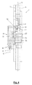
- Fig. 3 shows a view of a pressing tongs 1 with an annular closed pliers head 2 in plate construction, which has two identical in shape cover plates 3 and 4.
- the cover plates 3 and 4 are generally symmetrical with respect to a pliers head plane 5 (FIG. Fig . 4 ) arranged.
- the pliers head plane 5 is determined by the two main directions of extension of the pliers head 2.
- Fig. 3 forms the pliers head plane 5 at the same time the plane of the drawing.
- two tool parts 6, 7 are arranged, which together form a tool.
- the tool part 6 is fixedly mounted in the pliers head 2, while the tool part 7 is arranged to be relatively movable.
- the tool part 7 is guided here linearly with the aid of the frame-shaped closed cover plates 3, 4.
- the tool parts 6 and 7 as mutually associated pressing dies, with which it is possible to permanently deform a workpiece 8 in a pressing operation, for example to produce a crimped connection.
- the workpiece 8 previously in a precisely defined relative position to the Tool parts 6 and 7 are brought.
- a positioner 9 which is mounted with a pivot bearing 10 with pivot axis 11 pivotally mounted on the pliers head 2.
- the pivot bearing 10 is designed and arranged such that its pivot axis 11 is located in a plane 12 which is parallel to the pliers head plane 5 (FIG. Fig. 4 ) is arranged.
- the plane 12 lies at some distance parallel to the pliers head plane 5. However, it can also coincide with the pliers head plane 5.
- the positioner 9 has a mounting plate 13, which is connected by means of a screw 14 to a part in the pliers head 2, which is on the one hand with the movable tool part and on the other hand with a drive 15 in connection.
- a drive 15 two levers 16 and 17 are used, which are mounted in a known manner on the pliers head 2 pivotally relative to each other and drive the movable tool part 7 linearly in the main extension direction of the pressing pliers 1.
- the positioner 9 has, in addition to the mounting plate 13, a pivot plate 18.
- the pivot plate 18 is pivotally connected to the mounting plate 13 via the pivot bearing 10, so that the pivot plate 18 can be pivoted about the pivot axis 11 (see. Fig . 7 and 8th ).
- the pivot plate 18 ( Fig. 5 ) has on its side facing away from the pliers head plane 5 a projecting bolt 19, which serves to facilitate gripping the pivot plate 18 for performing a pivoting about the pivot axis 11.
- the pivot plate 18 On its other, so the pliers head 2 facing side, the pivot plate 18 has at least one receiving location 20th Fig. 3 allows three receiving points 20 side by side on the positioner 9 and the pivot plate 18 recognize.
- the receiving points 20 are assigned to three nests on the tool parts 6 and 7 and determined, for example, for different diameters of workpieces 8.
- Each receiving point 20 is formed here as a recess in the back 21 of the pivot plate 18. But it is also possible, the receiving point 20 on the positioner 9 and the pivot plate 18 as a projection, in particular as a projecting pin form, to a z. B. sleeve or tubular workpiece 8 réellestecken here.
- Fig. 5 shows in a sectional view, the pivot plate 18 of the positioner 9.
- the pivot plate 18 may be formed in particular as a plastic molding or as a metal molding. It has in the lower part for the realization of the located on the pivot plate 18 parts of the Swivel bearing 10 preferably a plurality of projections 22 with open-edged recesses 23, with the aid of which they can be detachably attached to a bolt 24, which on the mounting plate 13 (FIGS. Fig. 6 ) is provided and stored.
- the bolt 24 and the open-edged recess 23 are provided in the mounted position with jointly aligned pivot axis 11.
- a magnet 25 is mounted, which in the working position ( Fig. 4 and Fig.
- the magnet 25 which acts between the pivot plate 18 and the mounting plate 13, could also be arranged on the mounting plate 13. Since the mounting plate 13 may be formed as a plastic molding or metal molding, this suitably has a bore 26 into which in the mounted position a steel pin 27 (FIG. Fig. 4 ) engages, which cooperates with the magnet 25.
- the steel pin also has the task of supporting the mounting plate 13 together with the screw 14 against rotation on the pliers head.
- the pivot plate 18 may have on its rear side 21 one or more cylindrical projections 28 which engage in holes not shown in the mounting plate 18 in the working position and engage. This measure can serve to eliminate an occurring in the realization of the pivot bearing 10 and / or by frequent use of the positioner 9 magnifying game in the pivot bearing 10 in the working position and in this way the working position of the positioner or the pivot plate 18 with to stabilize the inserted workpiece 8.
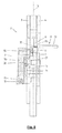
- the pivot plate 18 from the receiving position ( Fig. 7 ) into the working position ( Fig. 8 ) is pivotable about a pivot angle 29 about the pivot axis 11 of the pivot bearing 10.
- the swivel angle 29 should be at least 75 °. It is better if the pivoting angle 29 is more than 90 °, for example about 120 °, as in Fig. 5 shown.
- the pivot angle 29 is limited by a stop 30, which is formed by the cover plate 3 and to the one edge or corner of the pivot plate 18 in the Aufsteck ein ( Fig. 7 ) strikes.
- the stop 30 simultaneously forms an abutment for the pivot plate 18, so that the pivot plate 18 in the Aufsteckwolf ( Fig.
- a workpiece 8 is fixed and the workpiece 8 can be inserted accurately in the selected receiving location 20.
- a workpiece 8 is in Fig. 7 a connector shown, as it is needed in a crimp connection with a partially stripped electrical conductor, while two crimp connections must be made, namely once with the isolation of the electrical conductor and the other with the metal core of the electrical conductor.
- Fig. 8 shows the relative position of the parts before initiating such a processing step or crimping. It can be seen that the pivot plate 18 of the positioner in accordance with the pivot angle 29 from the attachment position Fig. 7 according to the working position Fig. 8 has been pivoted. The workpiece 8 in the form of the connector is thus positioned in exact position relative to the movable tool part 7. The axis of the workpiece 8 and the axis of the movable tool part 7 are aligned with each other. From the Fig. 7 and 8th it can be seen that the workpiece 8 is positioned from the one side into the pliers head 2 in the direction of the pliers head plane 5 perpendicular to the working position.
- the positioning stop 34 can be designed as a platen head 2 against spring force displaceable thin plate, as is well known.
- the positioning stop 34 only serves to establish the correct intended position of the electrical conductor 31.
- the positioning stop 34 has no significance for the positioning of the workpiece 8 in the pliers head during the working position.
- the positioning stop 34 is also matched to the relative position of the workpiece 8 in the working position in the pliers head. But you recognize it Fig.
- the conductor 31 After completion of the work or crimping process, the conductor 31 is connected to the workpiece 8 and remains when opening the pressing pliers in its relative position to the movable tool part 7, so that the totality of conductor 31 and workpiece 8 against the insertion movement of the electrical conductor 31 relative can be removed to the pliers head plane 5. After pivoting the pivot plate 18 of the positioner 9 in the Aufschwenk ein according to Fig. 7 a new workpiece 8 can be used and the operation can then be repeated.
- the described embodiment according to Fig. 3 to 8 is (in addition to other embodiments that can be combined with the features of the invention) in DE 198 32 884 C1 described.
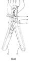
- FIG. 9 to 12 an exemplary embodiment of a pressing tongs according to the invention is shown, wherein the embodiment according to the Fig. 3 to 7 Corresponding components are identified by the same reference numerals with the addition of the letter a.
- the positioner 9 a is equipped with a boom or arm 35, which as a single part in Fig. 13 is shown.
- the arm 35 is formed as a shaped sheet metal part with a constant wall thickness.
- the arm 35 is formed with a connecting portion 36 and a tab 37 projecting from the connecting portion.
- the tab 37 is flat with a U-shaped outer contour.
- the tab 37 is oriented with respect to the pliers head plane 5 at an acute angle 41, wherein the angle 41 is preferably 60 ° to 85 °, in particular 70 ° to 80 °, for example approximately 75 °.
- the connecting portion 36 is formed with a strip of approximately constant width, which is angled U-shaped with a base leg 38 and two parallel side legs 39, 40.
- the base leg 38 has an approximately semi-circular recess 42 and two edge-closed or, as in Fig. 12
- the side legs 39, 40 are extended downwards with rod-shaped extensions 45, 46, which are angled in their side arms 39, 40 facing away from each other end portions 47, 48 by 90 ° to each other, wherein the in Installation state aligned with the pivot axis 11a-11a are oriented.
- the arm 35 is attached to the positioner 9a from the outside, the bolt 19 entering the recess 42 and the rear side of the base leg 38 coming into contact with the outside of the positioner 9a, while the side legs 39, 40 of the arm 35 are the positioner 9a grip around the side.
- a firm connection between the arm 35 and positioner 9a in that two screws 49, 50 are screwed through the recesses 43, 44 in threaded holes of the positioner 9a.
- the end regions 47, 48 each serve to support one of a spring element 51, here a spiral or leg spring.
- the spring element 51 has two legs, which are pivoted to produce a torsional force of the spring element 51 to each other.
- a leg 52 extends parallel to the extension 46 upwards and extends for the purpose of securing against the arm 35 in an angled end portion in a bore 53 in the side legs 40.
- the other leg of the spring member 51 is supported in a manner not shown on the pressing pliers 1a , For example, on the cover plate 3a, the mounting plate 13a or the pliers head 2a, from.
- the spring element 51 is biased so that this the positioner 9a with arm 35 in the direction of Fig. 10 shown working position and can secure in this, which can be done in addition to a fuse by the magnet 25.
- the tab 37 extends at an angle of 60 ° to 85 °, in particular 70 ° to 80 °, for example about 75 °, to the pliers head plane 5a, wherein the tab 37 is slightly inclined in the direction of the hand lever 16a, 17a , If a user's hand is placed on the hand levers 16a, 17a or if this includes the hand levers 16a, 17a, then the user can use a finger, preferably the index finger or middle finger, from outside according to Fig. 10 apply an actuating force to the tab 37, so that the tab 37 can be used in one-handed operation as an actuator 54.
Landscapes
- Engineering & Computer Science (AREA)
- Manufacturing & Machinery (AREA)
- Manufacturing Of Electrical Connectors (AREA)
- Press Drives And Press Lines (AREA)
Applications Claiming Priority (1)
| Application Number | Priority Date | Filing Date | Title |
|---|---|---|---|
| DE102008017366A DE102008017366A1 (de) | 2008-04-04 | 2008-04-04 | Presszange mit einem Positionierer |
Publications (3)
| Publication Number | Publication Date |
|---|---|
| EP2107650A2 true EP2107650A2 (fr) | 2009-10-07 |
| EP2107650A3 EP2107650A3 (fr) | 2011-05-11 |
| EP2107650B1 EP2107650B1 (fr) | 2013-12-18 |
Family
ID=40627156
Family Applications (1)
| Application Number | Title | Priority Date | Filing Date |
|---|---|---|---|
| EP09155540.9A Not-in-force EP2107650B1 (fr) | 2008-04-04 | 2009-03-18 | Pince de serrage dotée d'un positionneur |
Country Status (3)
| Country | Link |
|---|---|
| US (1) | US8161789B2 (fr) |
| EP (1) | EP2107650B1 (fr) |
| DE (1) | DE102008017366A1 (fr) |
Cited By (1)
| Publication number | Priority date | Publication date | Assignee | Title |
|---|---|---|---|---|
| EP2672580A1 (fr) * | 2012-06-05 | 2013-12-11 | Wezag GmbH Werkzeugfabrik | Tête de pince de sertissage |
Families Citing this family (19)
| Publication number | Priority date | Publication date | Assignee | Title |
|---|---|---|---|---|
| DE102009001949B4 (de) * | 2009-03-27 | 2011-02-24 | Wezag Gmbh Werkzeugfabrik | Gesenkhälfte und Presswerkzeug |
| US20110030447A1 (en) * | 2009-08-06 | 2011-02-10 | Thomas Emery Backenstoes | Crimping tool with pivotable workpiece holder |
| EP2305428B1 (fr) | 2009-09-30 | 2016-08-31 | Wezag GmbH Werkzeugfabrik | Pince |
| DE102010061148A1 (de) | 2010-12-09 | 2012-06-14 | Wezag Gmbh Werkzeugfabrik | Zangenkopf für eine Presszange |
| EP2672581A1 (fr) | 2012-06-05 | 2013-12-11 | Wezag GmbH Werkzeugfabrik | Pince de sertissage pour connecteur solaire avec aide au positionnement |
| USD740095S1 (en) * | 2012-06-05 | 2015-10-06 | Wezag Gmbh Werkzeugfabrik | Crimping pliers |
| EP2728681B1 (fr) | 2012-11-01 | 2016-07-06 | Pressmaster AB | Localisateur et dispositif d'arrêt de fil, outil de sertissage actionné à la main, procédé de positionnement et de maintien d'un connecteur et système |
| EP2995424B1 (fr) | 2014-09-11 | 2018-12-12 | Wezag GmbH Werkzeugfabrik | Pince |
| EP3300187B1 (fr) | 2016-09-22 | 2021-03-24 | Wezag GmbH Werkzeugfabrik | Positionneur d'outil de presse et outil de presse |
| EP3309915B1 (fr) * | 2016-10-14 | 2019-11-13 | Wezag GmbH Werkzeugfabrik | Pince à dénuder, couteau à dénuder, et procédé de dénudage |
| EP3312949B1 (fr) | 2016-10-24 | 2019-09-04 | Wezag GmbH Werkzeugfabrik | Positionneur d'outil de sertissage et procédé de fabrication de positionneur d'outil de sertissage |
| DE202016105959U1 (de) | 2016-10-24 | 2018-01-25 | Wezag Gmbh Werkzeugfabrik | Crimpwerkzeug-Positionierer, Crimpwerkzeugkopf und Crimpwerkzeug |
| US10840661B2 (en) | 2017-08-09 | 2020-11-17 | Panduit Corp. | Terminal locator for crimping tools |
| US11596998B2 (en) * | 2020-06-29 | 2023-03-07 | Te Connectivity Solutions Gmbh | Terminal locator for a hand tool |
| USD950341S1 (en) * | 2020-09-15 | 2022-05-03 | Hanlong Industrial Co., Ltd. | Crimping tool |
| USD1000237S1 (en) * | 2020-12-17 | 2023-10-03 | Weidmueller Interface Gmbh & Co. Kg | Pliers |
| US11837833B2 (en) * | 2020-12-18 | 2023-12-05 | Te Connectivity Solutions Gmbh | Terminal holding device for crimp hand tool |
| TWD214844S (zh) * | 2020-12-21 | 2021-10-21 | 加捷實業有限公司 | 壓接手工具 |
| TWD215831S (zh) * | 2021-04-26 | 2021-12-01 | 加捷實業有限公司 | 壓接手工具 |
Citations (2)
| Publication number | Priority date | Publication date | Assignee | Title |
|---|---|---|---|---|
| DE2718165A1 (de) | 1977-04-23 | 1978-10-26 | Lumberg Karl Kg | Crimpvorrichtung |
| DE19832884C1 (de) | 1998-07-22 | 1999-12-02 | Wezag Gmbh | Preßzange mit einem Zangenkopf und einem Positionierer |
Family Cites Families (5)
| Publication number | Priority date | Publication date | Assignee | Title |
|---|---|---|---|---|
| US3393438A (en) * | 1965-06-22 | 1968-07-23 | Amp Inc | Crimping tool |
| US4381661A (en) * | 1980-03-19 | 1983-05-03 | C. A. Weidmuller Gmbh & Co. | Tool having two working jaws |
| SE8302186D0 (sv) * | 1983-04-19 | 1983-04-19 | Weidmueller C A Gmbh Co | Kabelskotang med ettanslagorgan |
| SE8704191D0 (sv) * | 1987-10-28 | 1987-10-28 | Weidmueller C A Gmbh Co | Kabelskotang |
| SE8804084D0 (sv) * | 1988-11-11 | 1988-11-11 | C A Weidmueller Gmbh & Co | Lokator foer ett cripverktyg |
-
2008
- 2008-04-04 DE DE102008017366A patent/DE102008017366A1/de not_active Withdrawn
-
2009
- 2009-03-18 EP EP09155540.9A patent/EP2107650B1/fr not_active Not-in-force
- 2009-03-20 US US12/408,069 patent/US8161789B2/en not_active Expired - Fee Related
Patent Citations (2)
| Publication number | Priority date | Publication date | Assignee | Title |
|---|---|---|---|---|
| DE2718165A1 (de) | 1977-04-23 | 1978-10-26 | Lumberg Karl Kg | Crimpvorrichtung |
| DE19832884C1 (de) | 1998-07-22 | 1999-12-02 | Wezag Gmbh | Preßzange mit einem Zangenkopf und einem Positionierer |
Cited By (1)
| Publication number | Priority date | Publication date | Assignee | Title |
|---|---|---|---|---|
| EP2672580A1 (fr) * | 2012-06-05 | 2013-12-11 | Wezag GmbH Werkzeugfabrik | Tête de pince de sertissage |
Also Published As
| Publication number | Publication date |
|---|---|
| US8161789B2 (en) | 2012-04-24 |
| DE102008017366A1 (de) | 2009-10-08 |
| EP2107650B1 (fr) | 2013-12-18 |
| EP2107650A3 (fr) | 2011-05-11 |
| US20090249855A1 (en) | 2009-10-08 |
Similar Documents
| Publication | Publication Date | Title |
|---|---|---|
| EP2107650B1 (fr) | Pince de serrage dotée d'un positionneur | |
| EP2305428B1 (fr) | Pince | |
| DE19832884C1 (de) | Preßzange mit einem Zangenkopf und einem Positionierer | |
| EP2463969B1 (fr) | Tête de pince pour une pince de sertissage | |
| EP3012923B1 (fr) | Pince de pression | |
| EP2873122B1 (fr) | Outil de sertissage pour douille d'extrêmité de conducteur | |
| DE202008003703U1 (de) | Zange mit einem ein zweiteiliges Werkzeug aufweisenden Zangenkopf und einem Positionierer | |
| EP2562891B1 (fr) | Pince de pression | |
| EP3718184B1 (fr) | Mâchoires de serrage pour une pince à dénuder et pince à dénuder | |
| DE69408242T2 (de) | Verbesserungen in Bezug auf Drahtentmantelungswerkzeuge | |
| EP3614507A1 (fr) | Pinces à presser ou à sertir | |
| EP3159107B1 (fr) | Groupe de pinces manuelles | |
| WO2016023057A1 (fr) | Outil de cintrage et dispositif de préhension servant à manipuler l'outil de cintrage | |
| EP2787903B1 (fr) | Instrument médical | |
| EP2115829B1 (fr) | Dispositif de positionnement pour outils de sertissage | |
| EP3834989A1 (fr) | Outil pince à main et procédé de montage d'un tel outil | |
| EP2481492B1 (fr) | Outil de pliage pour le pliage à forme libre de tôles | |
| DE102010024610B4 (de) | Setzgerät mit einer variablen Setzhubeinstellung | |
| EP1319456A1 (fr) | Découpeur de câbles | |
| DE102007005176B4 (de) | Positionierungseinrichtung für Crimpwerkzeuge | |
| EP2672581A1 (fr) | Pince de sertissage pour connecteur solaire avec aide au positionnement | |
| EP4200946B1 (fr) | Pince manuelle conçue pour réaliser un sertissage et pince manuelle pourvue d'une tête de pince | |
| EP0124919A2 (fr) | Pince à pressage munie d'une pièce d'arrêt utilisée pour presser des souliers de câble | |
| DE102010007917B4 (de) | Handbetätigtes Werkzeug | |
| WO2024223573A1 (fr) | Pince à dénuder comprenant deux mâchoires de pince |
Legal Events
| Date | Code | Title | Description |
|---|---|---|---|
| PUAI | Public reference made under article 153(3) epc to a published international application that has entered the european phase |
Free format text: ORIGINAL CODE: 0009012 |
|
| AK | Designated contracting states |
Kind code of ref document: A2 Designated state(s): AT BE BG CH CY CZ DE DK EE ES FI FR GB GR HR HU IE IS IT LI LT LU LV MC MK MT NL NO PL PT RO SE SI SK TR |
|
| AX | Request for extension of the european patent |
Extension state: AL BA RS |
|
| PUAL | Search report despatched |
Free format text: ORIGINAL CODE: 0009013 |
|
| AK | Designated contracting states |
Kind code of ref document: A3 Designated state(s): AT BE BG CH CY CZ DE DK EE ES FI FR GB GR HR HU IE IS IT LI LT LU LV MC MK MT NL NO PL PT RO SE SI SK TR |
|
| AX | Request for extension of the european patent |
Extension state: AL BA RS |
|
| 17P | Request for examination filed |
Effective date: 20110812 |
|
| AKX | Designation fees paid |
Designated state(s): AT BE BG CH CY CZ DE DK EE ES FI FR GB GR HR HU IE IS IT LI LT LU LV MC MK MT NL NO PL PT RO SE SI SK TR |
|
| GRAP | Despatch of communication of intention to grant a patent |
Free format text: ORIGINAL CODE: EPIDOSNIGR1 |
|
| INTG | Intention to grant announced |
Effective date: 20130806 |
|
| GRAS | Grant fee paid |
Free format text: ORIGINAL CODE: EPIDOSNIGR3 |
|
| GRAA | (expected) grant |
Free format text: ORIGINAL CODE: 0009210 |
|
| AK | Designated contracting states |
Kind code of ref document: B1 Designated state(s): AT BE BG CH CY CZ DE DK EE ES FI FR GB GR HR HU IE IS IT LI LT LU LV MC MK MT NL NO PL PT RO SE SI SK TR |
|
| REG | Reference to a national code |
Ref country code: GB Ref legal event code: FG4D Free format text: NOT ENGLISH |
|
| REG | Reference to a national code |
Ref country code: CH Ref legal event code: EP |
|
| REG | Reference to a national code |
Ref country code: AT Ref legal event code: REF Ref document number: 645961 Country of ref document: AT Kind code of ref document: T Effective date: 20140115 |
|
| REG | Reference to a national code |
Ref country code: IE Ref legal event code: FG4D Free format text: LANGUAGE OF EP DOCUMENT: GERMAN |
|
| REG | Reference to a national code |
Ref country code: DE Ref legal event code: R096 Ref document number: 502009008530 Country of ref document: DE Effective date: 20140213 |
|
| REG | Reference to a national code |
Ref country code: SE Ref legal event code: TRGR |
|
| REG | Reference to a national code |
Ref country code: NL Ref legal event code: VDEP Effective date: 20131218 |
|
| PG25 | Lapsed in a contracting state [announced via postgrant information from national office to epo] |
Ref country code: FI Free format text: LAPSE BECAUSE OF FAILURE TO SUBMIT A TRANSLATION OF THE DESCRIPTION OR TO PAY THE FEE WITHIN THE PRESCRIBED TIME-LIMIT Effective date: 20131218 Ref country code: NO Free format text: LAPSE BECAUSE OF FAILURE TO SUBMIT A TRANSLATION OF THE DESCRIPTION OR TO PAY THE FEE WITHIN THE PRESCRIBED TIME-LIMIT Effective date: 20140318 Ref country code: LT Free format text: LAPSE BECAUSE OF FAILURE TO SUBMIT A TRANSLATION OF THE DESCRIPTION OR TO PAY THE FEE WITHIN THE PRESCRIBED TIME-LIMIT Effective date: 20131218 Ref country code: HR Free format text: LAPSE BECAUSE OF FAILURE TO SUBMIT A TRANSLATION OF THE DESCRIPTION OR TO PAY THE FEE WITHIN THE PRESCRIBED TIME-LIMIT Effective date: 20131218 |
|
| REG | Reference to a national code |
Ref country code: LT Ref legal event code: MG4D |
|
| PG25 | Lapsed in a contracting state [announced via postgrant information from national office to epo] |
Ref country code: LV Free format text: LAPSE BECAUSE OF FAILURE TO SUBMIT A TRANSLATION OF THE DESCRIPTION OR TO PAY THE FEE WITHIN THE PRESCRIBED TIME-LIMIT Effective date: 20131218 |
|
| PG25 | Lapsed in a contracting state [announced via postgrant information from national office to epo] |
Ref country code: EE Free format text: LAPSE BECAUSE OF FAILURE TO SUBMIT A TRANSLATION OF THE DESCRIPTION OR TO PAY THE FEE WITHIN THE PRESCRIBED TIME-LIMIT Effective date: 20131218 Ref country code: IS Free format text: LAPSE BECAUSE OF FAILURE TO SUBMIT A TRANSLATION OF THE DESCRIPTION OR TO PAY THE FEE WITHIN THE PRESCRIBED TIME-LIMIT Effective date: 20140418 |
|
| PG25 | Lapsed in a contracting state [announced via postgrant information from national office to epo] |
Ref country code: ES Free format text: LAPSE BECAUSE OF FAILURE TO SUBMIT A TRANSLATION OF THE DESCRIPTION OR TO PAY THE FEE WITHIN THE PRESCRIBED TIME-LIMIT Effective date: 20131218 Ref country code: NL Free format text: LAPSE BECAUSE OF FAILURE TO SUBMIT A TRANSLATION OF THE DESCRIPTION OR TO PAY THE FEE WITHIN THE PRESCRIBED TIME-LIMIT Effective date: 20131218 Ref country code: PT Free format text: LAPSE BECAUSE OF FAILURE TO SUBMIT A TRANSLATION OF THE DESCRIPTION OR TO PAY THE FEE WITHIN THE PRESCRIBED TIME-LIMIT Effective date: 20140418 Ref country code: CY Free format text: LAPSE BECAUSE OF FAILURE TO SUBMIT A TRANSLATION OF THE DESCRIPTION OR TO PAY THE FEE WITHIN THE PRESCRIBED TIME-LIMIT Effective date: 20131218 Ref country code: SK Free format text: LAPSE BECAUSE OF FAILURE TO SUBMIT A TRANSLATION OF THE DESCRIPTION OR TO PAY THE FEE WITHIN THE PRESCRIBED TIME-LIMIT Effective date: 20131218 Ref country code: RO Free format text: LAPSE BECAUSE OF FAILURE TO SUBMIT A TRANSLATION OF THE DESCRIPTION OR TO PAY THE FEE WITHIN THE PRESCRIBED TIME-LIMIT Effective date: 20131218 Ref country code: PL Free format text: LAPSE BECAUSE OF FAILURE TO SUBMIT A TRANSLATION OF THE DESCRIPTION OR TO PAY THE FEE WITHIN THE PRESCRIBED TIME-LIMIT Effective date: 20131218 Ref country code: CZ Free format text: LAPSE BECAUSE OF FAILURE TO SUBMIT A TRANSLATION OF THE DESCRIPTION OR TO PAY THE FEE WITHIN THE PRESCRIBED TIME-LIMIT Effective date: 20131218 |
|
| REG | Reference to a national code |
Ref country code: DE Ref legal event code: R097 Ref document number: 502009008530 Country of ref document: DE |
|
| PLBE | No opposition filed within time limit |
Free format text: ORIGINAL CODE: 0009261 |
|
| STAA | Information on the status of an ep patent application or granted ep patent |
Free format text: STATUS: NO OPPOSITION FILED WITHIN TIME LIMIT |
|
| PG25 | Lapsed in a contracting state [announced via postgrant information from national office to epo] |
Ref country code: DK Free format text: LAPSE BECAUSE OF FAILURE TO SUBMIT A TRANSLATION OF THE DESCRIPTION OR TO PAY THE FEE WITHIN THE PRESCRIBED TIME-LIMIT Effective date: 20131218 Ref country code: LU Free format text: LAPSE BECAUSE OF FAILURE TO SUBMIT A TRANSLATION OF THE DESCRIPTION OR TO PAY THE FEE WITHIN THE PRESCRIBED TIME-LIMIT Effective date: 20140318 |
|
| REG | Reference to a national code |
Ref country code: CH Ref legal event code: PL |
|
| 26N | No opposition filed |
Effective date: 20140919 |
|
| GBPC | Gb: european patent ceased through non-payment of renewal fee |
Effective date: 20140318 |
|
| REG | Reference to a national code |
Ref country code: IE Ref legal event code: MM4A Ref country code: DE Ref legal event code: R097 Ref document number: 502009008530 Country of ref document: DE Effective date: 20140919 |
|
| PG25 | Lapsed in a contracting state [announced via postgrant information from national office to epo] |
Ref country code: IE Free format text: LAPSE BECAUSE OF NON-PAYMENT OF DUE FEES Effective date: 20140318 Ref country code: CH Free format text: LAPSE BECAUSE OF NON-PAYMENT OF DUE FEES Effective date: 20140331 Ref country code: LI Free format text: LAPSE BECAUSE OF NON-PAYMENT OF DUE FEES Effective date: 20140331 Ref country code: GB Free format text: LAPSE BECAUSE OF NON-PAYMENT OF DUE FEES Effective date: 20140318 |
|
| PG25 | Lapsed in a contracting state [announced via postgrant information from national office to epo] |
Ref country code: SI Free format text: LAPSE BECAUSE OF FAILURE TO SUBMIT A TRANSLATION OF THE DESCRIPTION OR TO PAY THE FEE WITHIN THE PRESCRIBED TIME-LIMIT Effective date: 20131218 |
|
| PG25 | Lapsed in a contracting state [announced via postgrant information from national office to epo] |
Ref country code: MT Free format text: LAPSE BECAUSE OF FAILURE TO SUBMIT A TRANSLATION OF THE DESCRIPTION OR TO PAY THE FEE WITHIN THE PRESCRIBED TIME-LIMIT Effective date: 20131218 |
|
| REG | Reference to a national code |
Ref country code: FR Ref legal event code: PLFP Year of fee payment: 8 |
|
| PG25 | Lapsed in a contracting state [announced via postgrant information from national office to epo] |
Ref country code: MC Free format text: LAPSE BECAUSE OF FAILURE TO SUBMIT A TRANSLATION OF THE DESCRIPTION OR TO PAY THE FEE WITHIN THE PRESCRIBED TIME-LIMIT Effective date: 20131218 |
|
| PG25 | Lapsed in a contracting state [announced via postgrant information from national office to epo] |
Ref country code: BG Free format text: LAPSE BECAUSE OF FAILURE TO SUBMIT A TRANSLATION OF THE DESCRIPTION OR TO PAY THE FEE WITHIN THE PRESCRIBED TIME-LIMIT Effective date: 20131218 Ref country code: IT Free format text: LAPSE BECAUSE OF FAILURE TO SUBMIT A TRANSLATION OF THE DESCRIPTION OR TO PAY THE FEE WITHIN THE PRESCRIBED TIME-LIMIT Effective date: 20131218 Ref country code: GR Free format text: LAPSE BECAUSE OF FAILURE TO SUBMIT A TRANSLATION OF THE DESCRIPTION OR TO PAY THE FEE WITHIN THE PRESCRIBED TIME-LIMIT Effective date: 20140319 |
|
| PG25 | Lapsed in a contracting state [announced via postgrant information from national office to epo] |
Ref country code: HU Free format text: LAPSE BECAUSE OF FAILURE TO SUBMIT A TRANSLATION OF THE DESCRIPTION OR TO PAY THE FEE WITHIN THE PRESCRIBED TIME-LIMIT; INVALID AB INITIO Effective date: 20090318 Ref country code: BE Free format text: LAPSE BECAUSE OF FAILURE TO SUBMIT A TRANSLATION OF THE DESCRIPTION OR TO PAY THE FEE WITHIN THE PRESCRIBED TIME-LIMIT Effective date: 20140331 Ref country code: TR Free format text: LAPSE BECAUSE OF FAILURE TO SUBMIT A TRANSLATION OF THE DESCRIPTION OR TO PAY THE FEE WITHIN THE PRESCRIBED TIME-LIMIT Effective date: 20131218 |
|
| REG | Reference to a national code |
Ref country code: FR Ref legal event code: PLFP Year of fee payment: 9 |
|
| REG | Reference to a national code |
Ref country code: FR Ref legal event code: PLFP Year of fee payment: 10 |
|
| PGFP | Annual fee paid to national office [announced via postgrant information from national office to epo] |
Ref country code: DE Payment date: 20171219 Year of fee payment: 10 |
|
| PGFP | Annual fee paid to national office [announced via postgrant information from national office to epo] |
Ref country code: SE Payment date: 20180326 Year of fee payment: 10 Ref country code: FR Payment date: 20180326 Year of fee payment: 10 Ref country code: AT Payment date: 20180320 Year of fee payment: 10 |
|
| PG25 | Lapsed in a contracting state [announced via postgrant information from national office to epo] |
Ref country code: MK Free format text: LAPSE BECAUSE OF FAILURE TO SUBMIT A TRANSLATION OF THE DESCRIPTION OR TO PAY THE FEE WITHIN THE PRESCRIBED TIME-LIMIT Effective date: 20131218 |
|
| REG | Reference to a national code |
Ref country code: DE Ref legal event code: R119 Ref document number: 502009008530 Country of ref document: DE |
|
| REG | Reference to a national code |
Ref country code: SE Ref legal event code: EUG |
|
| PG25 | Lapsed in a contracting state [announced via postgrant information from national office to epo] |
Ref country code: SE Free format text: LAPSE BECAUSE OF NON-PAYMENT OF DUE FEES Effective date: 20190319 |
|
| REG | Reference to a national code |
Ref country code: AT Ref legal event code: MM01 Ref document number: 645961 Country of ref document: AT Kind code of ref document: T Effective date: 20190318 |
|
| PG25 | Lapsed in a contracting state [announced via postgrant information from national office to epo] |
Ref country code: DE Free format text: LAPSE BECAUSE OF NON-PAYMENT OF DUE FEES Effective date: 20191001 Ref country code: AT Free format text: LAPSE BECAUSE OF NON-PAYMENT OF DUE FEES Effective date: 20190318 |
|
| PG25 | Lapsed in a contracting state [announced via postgrant information from national office to epo] |
Ref country code: FR Free format text: LAPSE BECAUSE OF NON-PAYMENT OF DUE FEES Effective date: 20190331 |